Troubleshooting methods. Troubleshooting Program
Finding a faulty element takes a third of the repair time. Since the number of elements in the objects of automation tools is large, a direct enumeration of elements to assess their state is impossible. When performing troubleshooting work, certain rules must be followed. The search technology can be broken down into the basic operations shown in Figure 3.1.
Figure 3.1 - Technology for searching for failures (faults)
The troubleshooting process is reduced to conducting various checks and deciding on the further development of the search based on the results of the check.
The troubleshooting process has two stages: selection of the sequence of checking elements; selection of the method for carrying out individual verification operations.
The search can be carried out in advance certain sequence checks or the course of each subsequent check is determined by the result of the previous one. Depending on this, the following verification methods:
- sequential element-by-element;
- consecutive group;
combinational.
The choice of the sequence of checks depends on the design of products, and may change in the process of accumulating information on the reliability and laboriousness of checking elements.
3.2.1 Sequential element-by-element method consists in the fact that the elements of the products when troubleshooting are checked one by one in a certain, predetermined sequence. If the next checked element turned out to be serviceable, then proceed to checking the next element. When a defective element is found, the search stops and the element is replaced (repaired). Then the object is checked for operability. If at the same time the object (system) does not function normally, then proceed to further verification. Moreover, the check begins from the position at which the faulty element was detected. If a second faulty element is found, it is also replaced or repaired (recovered), and the object is again checked for operability. And so on until the object or system functions normally.
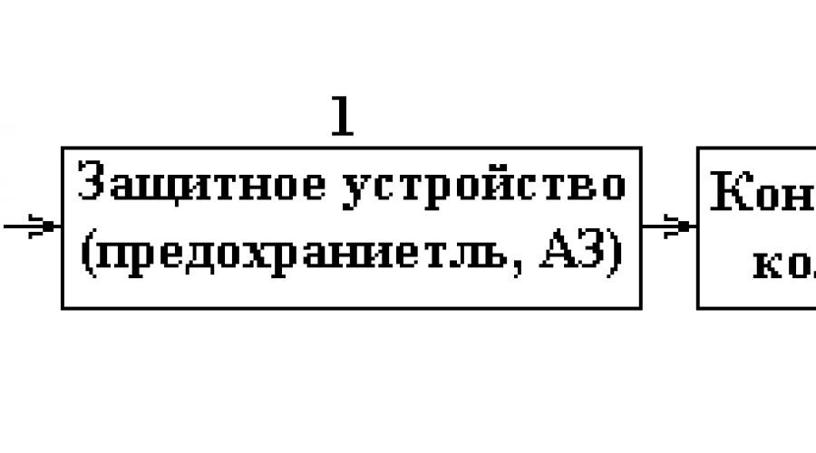
EXAMPLE The simplest example of the use of such a method can be troubleshooting in the automatic control system of one of the process parameters. The regulator is checked first, then the actuator, then the amplifier, and so on. Thus, an object is installed, the malfunction of which caused a disruption in the normal functioning of the automatic control system (Figure 3.2).
Figure 3.2 - Structural scheme automatic control systems of the “Crystal” type
If, for example, a malfunction is detected in the actuator, the element-wise structure of this device is considered (Figure 3.3).

Figure 3.3 - Structural diagram of the actuator
Here you can set the following sequence of checking elements: 1-2-3-4-5-6-7-8. elements 1,2,4,7 and 8 may be the most vulnerable of them. Therefore, when using the element-by-element method of verification, there are two ways to sequence the control of elements.
When searching for a malfunction in a device, the object is first identified, the malfunction of which caused a disruption in the normal functioning of the device. Then, the element-by-element structure of the failed device object is considered.
When using the element-by-element verification method, it is possible two ways of element control order.
1) If the product uses elements whose test duration is approximately the same, then the test should begin with elements that have the least reliability.
2) If the reliability of the elements of a given product is approximately the same, then it is advisable to start checking with the element that requires the least time to check.
For the successful use of these rules, it is necessary to know not only the functional and schematic diagrams of objects and systems, but also to have a clear idea of the reliability of their elements.
The disadvantage of the method- comparatively a large number of checks. This is explained by the fact that this method does not use the functional relationships of elements when searching, although this makes the method universal, because it does not depend on the functional scheme of the system.
3.2.2 Sequential batch test method consists in the fact that all elements of the object, taking into account their functional relationships, are divided into separate groups and the serviceability of each group as a whole is controlled. The sequence of checks is determined by the result of the previous check. As the checks are carried out, the number of elements to be checked decreases. At the last stage of control, there should be one element in the group.
An EXAMPLE of troubleshooting using this method is given in functional diagram system in Figure 3.4 is one of the types of ACS.

Figure 3.4 - An example of a block diagram of the ACS
The scheme is divided into groups I-VIII. Then the structure is divided into two subgroups, and so on. In this case, the sequence of checks will be as follows:
a) The signal at point 4 is monitored. If it is normal, then go to point 6, because it is assumed that the failed element is in group V, VI, VII, VIII. If the signal at point 4 does not correspond to the norm, then the signal at point 2 is checked, because one of the elements I, II, III, IV is faulty. If the signal at point 2 is normal, then elements I, II are OK, and point 3 should be checked. This reveals which of the elements III or IV is faulty.
b) If during the control of points 4 and 6 the signal corresponds to the required parameters, then point 5 is controlled, as a result of which a faulty element V or VIII is determined.
With this method of troubleshooting, it is necessary to know the parameters of the signals at the test points.
If there are several faults in the object (system), then the troubleshooting scheme will not change. Moving along one of the branches of the structure, one inevitably comes to one of the faulty elements. After elimination of this malfunction (restoration of the element), the operability of the object is checked. If there is a fault, the search process continues, which should lead to a second faulty element, and so on.
This method is also called the midpoint method. However, in the general case, the number into which the block diagram of an object (system) is divided may not be equal to two. It is necessary to break up the system, taking into account the functional connections of individual elements and the reliability of their work.
With the group method of checks, checks are distinguished “ with an exception" And " without exception”.
The check “with an exception” consists in the fact that the conclusion about the operability of one of the groups of elements is made on the basis of the check of other groups. For example, we have three groups of elements. Based on the results of the check, the serviceability of groups 1 and 2 was established. Without doing checks, we conclude that the faulty element is in the 3rd group.
During checks “without exception”, the performance of all groups is monitored. At the final stage, a “no exception” check is always carried out, which eliminates the possibility of error.
Dignity test sequences - a significant reduction in troubleshooting time.
This method requires knowledge of the functional relationships of individual elements and their reliability.
3.2.3 Essence combination method checks consists in the simultaneous measurement of several parameters. Based on the results of measurements of all parameters, a conclusion is made about a faulty element.
For the convenience of using this method, tables of the state of controlled parameters are compiled. In this case, you should choose a block, a node, a sequential unbranched group of cascades as elements.
In the first vertical column of the table indicate the elements of the block diagram, and in the first line - their parameters. The table is filled in by the arrows in accordance with the following rules.
Alternately, a malfunction is assumed only in given element. This fault causes the relevant parameters to be out of tolerance. "0" is put against these parameters in the table. If the specified fault does not affect any parameter, then “1” is set against this parameter.
EXAMPLE In the block diagram (Figure 3.5), we measure the parameters A, B, C, D.
We believe that element 1 is defective. Then, it is obvious that all parameters A, B, C and D will go beyond the tolerances. Against these parameters in Table 3.2, “0” is set, i.e. the first row of the table will consist of only zeros. Then we assume that element 2 is faulty, while parameters A, B and C will not comply with the standards, and parameter D will be normal. The second line should be written "0001". Thus, iterate over all the elements and analyze the state of the parameters. Identical lines (7 and 8 of Table 3.2) indicate that this system does not distinguish between the failure parameters of elements 7 and 8. In this case, the elements are combined into one or entered additional parameter to distinguish them.

Figure 3.5 - To the use of the combination method of checks.
Table 3.2 - Status Graph
| Elements | Options | |||
| A | IN | WITH | D | |
To detect a faulty element using such a table, proceed as follows. The operator writes the parameter values as a number consisting of zeros and ones, according to the specified rule. To determine the faulty element, the resulting number is compared with the numbers in the rows of the table. Which line of the table matches the results of measuring parameters, that element is faulty. If the parameter measurement result (number) does not match any row of the table, several elements are faulty.
Dignity This method has a relatively short troubleshooting time, but its implementation is difficult.
3.2.4 The sequence of the troubleshooting process is called search programs. A certain sequence of checks, providing the minimum value of the mathematical expectation of the time of checks, is calculated by creating a mathematical model of the process of searching for a failed element.
The object in which the fault occurred consists of n elements. Element failures are independent. If any of the elements fails, the object fails. To control the health of the element, it is possible to apply a control signal to the input and check the response to this signal at the output. Element failure rates are known q and required time τ to check their correctness. Determine the sequence of checks of elements that provide the shortest troubleshooting time.
The optimal sequence must have the following property
 , (3.1)
where τ is the average time for checking a good element;
q is the conditional probability of element failure.
If the health check time of all elements are equal, then the optimal sequence takes the form
q 1 >q 2 >…>q n -1. (3.2)
Those. element serviceability control should be carried out in descending order of the conditional probability of element failures.
Sequence (3.2) can be written in a more convenient form
λ 1 >λ 2 >…> λ n-1, (3.3)
The average troubleshooting time for the program is calculated by the formula
 , (3.4)
where τ FROM. i is the time spent on measurements in case of failure of the i-th element.
In its turn
where τ R is the time spent on measurements at point R of the scheme;
r i is the number of measurements according to the program to detect the failure of the i-th element.
Taking into account (3.5)
 , (3.6)
The order of constructing programs can be seen in examples.
Example 3.1

Figure 3.6 - Structural diagram of the product A.
There is a scheme shown in Figure 3.6. Failure rates of elements: λ 1 =0.1 h -1 ; λ 2 =0.2 h -1 ; λ 3 =0.2 h -1 ; λ 4 =0.5 h -1 . Measurement time at the points of the scheme: τ 1 =5 min.; τ 2 =8 min.; τ 3 =12 min.; τ 4 =18 min. It is required to draw up an optimal scheme for a troubleshooting program, provided that one of the elements of product A failed.
Conditional failure probabilities are determined. For the method of successive element-by-element checks, the conditional failure probabilities q correspond in value to λ. Then q 1 =0.1; q 2 =0.2; q 3 =0.2; q 4 \u003d 0.5. Define private: τ 1 /q 1 =50; τ 2 /q 2 =40; τ 3 /q 3 =60; τ 4 /q 4 =36;
According to (3.1), the first measurement must be made at the output of the fourth (IV) element. If the signal desired type at the output of element IV, then the search should continue and the next measurements should be made at the output of the second (II) element, etc.
For an analytical representation of the troubleshooting process, as a rule, its graphical representation is used in the form of a troubleshooting program. Symbol element is made in the form of a rectangle, and the measurement is in the form of a circle inside with the numbers of the element behind which the measurement is made. Then the troubleshooting program will be represented by a branching diagram consisting of circles with two outputs indicating the measurement result (there is a desired signal or not - “yes” or “no”) and ending with rectangles indicating the faulty element.
The search program for Example 3.1 is shown in Figure 3.7.

Figure 3.7 - Troubleshooting program in product A
The average troubleshooting time for the program is calculated by formula (3.6). Then:
T PN \u003d q 1 (τ 4 + τ 2 + τ 1) + q 2 (τ 4 + τ 2) + q 3 (τ 4 + τ 2 + τ 1) + q 4 τ 4 \u003d 0.1 (18 + 8+ 5)+0.2(18+6)+0.2(18+8+5)+0.5*18=23.5 min.
Example 3.2.
There is a scheme shown in Figure 3.8. Failure rates of elements: λ 1 =0.56*10 -4 h -1 ; λ 2 \u003d 0.48 * 10 -4 h -1; λ 3 \u003d 0.26 * 10 -4 h -1; λ 4 \u003d 0.2 * 10 -4 h -1; λ 5 \u003d 0.32 * 10 -4 h -1; λ 6 \u003d 0.18 * 10 -4 h -1. The measurement time at all points is the same and is 2 min. It is required to create an optimal troubleshooting program, provided that one of the elements has failed.
Figure 3.8 - Structural diagram of product B
To reduce the troubleshooting time, the method of sequential batch testing is used, i.e. the measurement of the response to the control signal is made at the point of the circuit, which divides the suspected faulty circuit by probability (intensity) in half.
Hence, the conditional probability of failures corresponds to the intensity value with a coefficient of 0.5 (half the value).
Then conditional failure probabilities: q 1 =0.28; q 2 =0.24; q 3 =0.13; q 4 =0.10; q 5 =0.16; q 6 \u003d 0.09.
The circuit consists of series-connected elements. You can use one control signal applied to the input of the first element. In this case, the first measurement must be made after the second element, because q 1 +; q 2 \u003d 0.52, closest to the division of the scheme in terms of probability in half. If the desired signal is not present after the second element, then a conclusion is made about the failure of the first or second element and the measurement is made after the first element. If there is a desired signal after the second element, then a conclusion is made about a malfunction of the right side of the circuit, which, by probability, is best halved at the measurement point after the fourth element, and so on.
The troubleshooting program in this circuit is shown in Figure 3.9.
 |
Figure 3.9 - Troubleshooting program in product B.
Average troubleshooting time for the program:
T P.N. =0.28(2+2)+0.24(2+2)+0.13(2+2+2)+0.20(2+2+2)+0.16(2+2+2 )+0.9(2+2+2)=5.56 min.
3.2.5 When troubleshooting, in addition to choosing a method and a troubleshooting program for an object (system), it is necessary to choose a methodology (methods) for checking the health of individual elements. Most common ways to check the health of elements:
Visual inspection;
Control switches and adjustments;
Intermediate measurements;
Comparison;
Typical malfunctions;
Isolation of a block or cascade, node;
Test - signals.
Visual inspection usually involves the use of sight and hearing. They allow you to control the installation status of the SA, cables, individual elements, printed circuit boards etc., as well as check the operation of a number of units, less often by ear.
Advantage this kind of checks in simplicity.
Flaw– Possibilities for determining the faulty element are limited. A malfunction can only be determined with clearly expressed external signs: a change in the color of the element under the influence of temperature, sparking, the appearance of smoke and smell from burning wire insulation, etc. Such signs are rare. In addition, interdependent failures are often encountered in practice, therefore, even if a faulty element is found by external inspection, additional checks must be carried out to identify the true causes of the failure (for example, when a fuse fails, the blown thread of which is visible “by eye”).
Method of control switching and adjustments requires an assessment of external signs of malfunctions by analyzing circuits and using switching, adjustment, current monitoring elements (signal lights, built-in devices, circuit breakers, etc.). In this case, a faulty node, block or path of the object (system) scheme is determined, i.e. a set of elements that perform a specific function of the object (converting, indicator units, protection or switching unit, transmission path, etc.).
Dignity method in the speed and simplicity of checking the assumption about the state of the sections of the object circuit.
Flaw– limitation, because allows you to identify areas, rather than a specific location of damage.
Method of intermediate measurements is the most common and basic for electrical and electronic devices. The parameters of a system, block, assembly or element are determined using manual portable or automated built-in control and measuring equipment (CIA) or special measuring devices, automatic control systems.
At the same time, power modes, parameters of communication lines are measured, measurements are taken at control points. The speed of finding a fault is largely ensured by the ability of the maintenance personnel to correctly take measurements. The obtained values of the parameters are compared with their values from the technical documentation, with the tables of modes of this product.
Replacement method consists in the fact that instead of an element (assembly, block, etc.) suspected of a malfunction, a similar known-good element is installed. After replacement, the object (system) is checked for functioning. If at the same time the system parameters are within the normal range, then it is concluded that the replaced element is faulty. The advantage of this method is simplicity. But in practice, this method has limitations, firstly, due to the lack of spare elements, and secondly, due to the need for adjustments due to insufficient interchangeability.
Dependent failures can lead to their failure again installed element, so this type of test is used when the suspect element is easily removable and inexpensive.
Comparison method - the mode of a faulty section (node, block) of an object or system is compared with the mode of a similar section of a healthy object. The advantage of the method in the absence of the need for knowledge of absolute values, measured values and parameters. At the same time, this method allows to determine rather complex faults. The disadvantage of this method is the need for a spare (bench) set of equipment and, as a result, the possibility of using this method only in a laboratory.
At method of characteristic faults refusal is sought on the basis of known characteristic features. Such malfunctions and their symptoms are presented in the form of tables in the operating instructions for the SA.
Tables of characteristic faults have a number of disadvantages, of which the most significant are the following:
The tables do not provide an unambiguous relationship between failure symptoms and possible malfunctions: several different malfunctions are attached to one symptom and usually without any indication of the features of their appearance;
The tables often do not contain instructions for conducting tests aimed at clarifying the cause of failures. A single external sign cannot indicate a specific reason for the failure, and to find it, a logical comparison of a number of external signs is necessary, including indications of control devices and test results;
The failure search actions recommended by the tables do not contain cause-and-effect relationships and are not distributed in their order, while the real search is a clear sequence of various checks (tests).
Test Signals are widely used in various computers, in computing devices. During this test, a signal with certain characteristics is applied to the input of the controlled device. Analysis of the output signal allows you to determine the location of the failed element.
Block insulation(node, section, cascade) substantiated by the fact that in some cases a block or cascade is connected by a large number of functional connections with other parts of the object. If such a unit fails, it is difficult to determine where the malfunction occurred - in the unit itself or in functionally related parts of the product. Disconnecting some functional links sometimes allows you to localize the location of the faulty element.
Each of the considered private troubleshooting methods has significant limitations, therefore, in the practice of repairing instrumentation and automatic equipment, several private methods are usually used together. This combination of methods reduces the overall search time and thus contributes to its success.
When looking for a malfunction in the equipment, various methods and methods are used. There are the following troubleshooting methods:
1. Sequential element-by-element checks.
2. Group checks.
3. Combination.
The method of successive element-by-element checks consists in checking the elements of the system one by one in a certain sequence, predetermined.
As a result of testing each element, its condition is established. If the checked element is correct, then the next one in order is checked. (You can check sequentially along the signal path, or in another predetermined order). The identified faulty element is restored, then a comprehensive check of the equipment is carried out.
The method of group checks is that by measuring one or more parameters, a group of elements is determined in which there are malfunctions. Then another series of measurements is carried out, which makes it possible to identify a subgroup of elements, including the faulty one.
As a result of a sequential series of checks, the area of the faulty part is gradually narrowed until a specific faulty element is installed.
The combination method consists in the fact that in the process of troubleshooting a certain set of parameters is measured. Based on the results of these measurements, a faulty element is determined. Analysis of the state of the system is carried out after a complete group of checks.
When applying any troubleshooting method, several methods of checking the condition of equipment (elements, assemblies, equipment) can be used:
The method of external inspection consists in examining blocks (assemblies) in which failure is expected. In this case, the main attention is drawn to the state of the electrical installation (insulation damage, breaks, short circuits, traces of breakdown, etc.), on appearance resistors, capacitors, transformers, contact systems of switches, relays, etc.
The method of replacement consists in the fact that individual elements of the system (blocks, removable parts), which are supposed to be faulty, are replaced with obviously operable ones. If, after replacement, normal operation is restored, then a conclusion is made about the malfunction of the replaced element.
The comparison method is used in cases where there are no voltage, resistance, etc. maps in the technical documentation. Then the mode of the checked elements during troubleshooting is compared with the mode of a serviceable device of the same type.
The method of control switching and checks consists in the use of controls, measuring and indicator devices to determine a faulty path or unit by successively switching the equipment to various operating modes.
The method of intermediate measurements is used to check nodes, blocks, equipment elements that cannot be checked by other methods.
To check the status at the control points of the equipment, voltages, frequencies and other signal parameters are measured. The measurement results are compared with the technical documentation data.
Refurbished products are tested for compliance with the measurements of the main specifications and bringing them (by adjustments) to the norms established by TU.
Troubleshooting Sequence
Before proceeding with the repair, it is necessary to study well circuit diagram equipment, controls on its front panel and a method for checking performance. It is also necessary to study the devices used in the repair.
All hardware failures can be divided into three groups:
1. The equipment does not work at all. In such cases, the real probability of a malfunction lies either in the power sources or in the common nodes of the equipment. It is possible that the equipment does not work for some one and, perhaps, simple reason: a fuse has blown, an open or short circuit in the circuit, the electrolytic capacitor of the power filter has closed, etc. This “simple” reason, with the equipment switched on for a long time, can lead to failure of other parts and cause more complex malfunctions. A malfunction of this kind is simple in the sense that if it is detected and eliminated, the equipment will begin to work normally and will not require additional adjustments. Not always the equipment does not work due to the failure of single parts. There are times when replacing a defective part does not return it to normal operation and more complex adjustments are required.
2. The equipment is not fully functional. For example, only the transmit path or the receive path is operational. The failure can also be associated, as in the first case, with the failure of individual parts and components of the faulty path.
3. The equipment works, but does not comply with the technical specifications. For example, signal distortion, overestimation or underestimation of levels. In such cases, it should be assumed that the transistor mode has changed, the parameters of the radio components have changed, etc.
Therefore, it is necessary to seriously examine the state of the equipment. This study may consist in measuring the power modes of transistors, taking a level diagram, etc.
The appearance of malfunctions in the equipment is possible when it is turned on or during operation. The basis for the repair in the laboratory is the first option, when for some reason (long-term storage, transportation, poor quality preventive work etc.) multiple faults may occur. The equipment located at each workplace has artificially introduced malfunctions. The causes of malfunctions, as a rule, are not determined by the method of external examination. However, in general, troubleshooting should be carried out in the following sequence:
1. Conduct an external inspection in order to collect the first information about the symptoms of malfunctions and avoid wasting time searching for false malfunctions. During an external examination it is necessary:
make sure that the supply voltage is supplied correctly and the power switches are installed, that the connecting cables are connected securely, that the blocks are tightly inserted into the packages;
check the correct installation of switches, switching blocks, the integrity of the fuses.
If signs of malfunctions already appeared when the equipment was turned on, then, first of all, the readings of alarm and control devices should be analyzed. The information obtained in this case is usually enough to determine where to look for a malfunction. The sound and optical signaling devices of the equipment are triggered when the following types malfunctions:
loss of voltage at the outputs of power supplies and blown fuses;
malfunctions of the remote power system;
loss of currents of linear control frequencies and disruption of normal AGC operation;
loss of carrier currents and control oscillations at the output of generating equipment.
External inspection is also mandatory in the case when the malfunction is already determined before the block, node. In this case, external inspection determines burnt parts, installation failure, relay and switch contacts, soldering integrity, lack of touch, fastening reliability, operation of the MRU motor, etc.
The method of troubleshooting by external inspection is most effective for malfunctions of an emergency nature (smoke, pungent odor, sparking of contacts).
2. By checking the operability of the equipment, establish the faulty sections of the paths or the fault of individual packages or blocks.
3. By measuring the level diagram in the control slots, determine bad block if it was not defined in the health check. At this stage, it is sometimes advisable to use the replacement method, for example, replacing the block with a known good one from the spare parts package.
4. Having connected the faulty unit to the equipment using repair hoses and measuring the levels at various points, determine the faulty unit. In this case, one should not always strive for high measurement accuracy. It is enough just to make sure the presence or absence of a signal. When removing the level diagram, the first measurement point should be chosen in such a way that you can make sure that the measuring signal is correctly applied to the input of the tested section. The point of each subsequent measurement must be chosen so that the area to be checked would be divided in it into two equally reliable parts, and to ensure the availability of connection measuring instruments to the node exit. With this method, less time is spent on verification.
5. Finding damage in the node should begin with an external examination, then check the supply voltage in the operating mode, if necessary, check the serviceability of individual elements. In the absence of the necessary data on the operating modes of the node (in the operational documentation, voltages on the transistor electrodes are not indicated for all nodes), it is advisable to use the comparison method with the parameters of a known-good node or the replacement method.
6. Replace the failed part with a good one. After that, make control measurements in the node that has undergone repair, and then in the block. In some cases (for example, when repairing amplifiers, PKK), the unit being repaired is adjusted and fine-tuned to fully comply with the data in the operational documentation.
Topic 1.18. Installation work with cable. Preparing the cable for installation. Harness knitting.
The preparation of a cable with a plastic sheath and with polyethylene insulation is basically no different from the preparation of cables with a lead sheath. All types of checks (for the tightness of the sheath, breakage and communication of the cores with the screen, breakage of the screen, insulation resistance of the cores) are performed in the same way as for lead-sheathed cables, but take into account that a bare copper core is used as ground. After making sure that the sheaths and cores are in good condition, the cable is temporarily strengthened on the consoles with wire bandages and proceed to cutting.
The preparation of the cable for laying begins with the fact that the drums with the cable are transported along the route in cars or special carts. If the route passes in close proximity to the railway track, the cable is transported on railway platforms, from which it is immediately laid in a trench. Before laying the cable in the ground, check the tightness of its sheath, the insulation resistance of the cores and the absence of short circuits and breaks in them.
To prepare the installation, it is first necessary to fix both ends of the cable, either according to the shape of the well, if splicing is done in the well, or in any form. Then, heat-shrinkable tubes must be installed on both ends of the cable, while the diameter of this tube should be slightly larger than the diameter of the cable. Parts of a polyethylene sleeve are put on top of the heat-shrinkable tubes.
Next, you need to fix special clamps at both ends of the cable, designed to organize the screen bus of the cable. After fixing the clamps, clean the polyethylene sheath and aluminum tape. The stripping length should be 15 mm on both edges. This length was chosen in order to obtain an even coupling as a result. Install the clamps on the aluminum tape and use a screwdriver to secure them to the end of the cable. Next, you need to connect both clamps with a temporary wire to provide a screen bus. Now you need to break the cable pairs into layers and ring them. Dialing is necessary to identify faults in the veins. Breaking into layers helps in the future to quickly and most importantly correctly twist both sections of the cable.
To check the cable for "breakage" and "message", sections of the sheath from 150 to 400 mm long are removed from its ends, the belt insulation is cut off and removed from the core.
It is not recommended to cut threads and tapes fastening bundles and layers. At one end of the cable, insulation is removed from all cores in sections from 20 to 25 mm long, then the cores are collected in bundles of 10-50 pairs. All cores of each bundle are short-circuited, tightly wrapping their stripped sections with a bare copper core. All bundles are interconnected by one segment of a stripped copper core. A bundle of bundles is connected to the screen or metal sheath of the cable.
An open test is performed at the opposite end of the cable. The wires of the handset (or headset) are connected in series with the battery and the screen (or metal sheath) of the cable. With a free wire from the tube, touch each core of the cable in turn (Figure 11.6). If a click is heard in the tube when touched, then the tested core is working. When touching a broken core, there will be no click.
Conductors being tested are not stripped. Contact is achieved due to the fact that when cutting the cable with a hacksaw or sector shears, the ends of the cores protrude beyond the edge of the insulation.
For ease of action, the free wire from the tube is connected to side cutters and they touch the ends of the cores. If necessary, the insulation of the tested core is stripped or bitten through.
After you have finished assembling your device, soldered the last element to the board, do not rush to turn it on immediately. Prepare a multimeter, open the circuit diagram and description of the circuit.
First you need to check the correct installation, check for a short circuit (short circuit). If you think that all the elements are soldered correctly, and you didn’t find a short circuit after dialing, then you can clear the tracks of rosin residues and apply power, but first you should check the resistance of the power circuit if it is suspiciously large, and if this is not specified in the one you are collecting scheme, then do not rush to turn on the scheme, double-check again. Whether the diode bridge was assembled correctly, whether the polarity was observed when soldering the capacitors in the power circuit, etc. eat 2-3 amps at idle. You can connect a low-power constant resistor of several ohms in series with the power circuit, this can save the device from failure. If the scheme contains power transistors or microcircuits that are mounted on a radiator, do not forget to isolate them from each other. Be careful when turning on the devices for the first time, as diodes and electrolytic capacitors can explode if turned on incorrectly or if the voltage is exceeded. Moreover, capacitors usually do not explode immediately, but first they heat up for some time. Do not leave devices turned on and not yet configured unattended.
troubleshooting
Before you start troubleshooting, if the device you are repairing is not familiar to you, you first need to get as much information as possible about this device, what kind of device, or what kind of node (PSU, amplifier, or other device), and you need to get a description and diagram of this device. Before you take out and start unscrewing the board, take a closer look to see if there is anything extra inside the case, a torn off piece, a fragment, etc. Do not forget to check even such circuit elements as a switch or power connector.
Before you start picking the board, discharge all capacitors, including high-voltage ceramic ones, you need to discharge with a resistor of about 100 ohms. If you forget to do this, then in the event of an accidental short circuit, or even during dialing, unsoldering radio components, the consequences can be terrible, more elements can fly, and you yourself can suffer. It is very important!
The check always starts with power and voltage check, check the mains voltage, fuse, then the power supply. Check the voltage at the output of the power supply and, if possible, the current at the output. It happens that the voltage is normal, and if you connect a light bulb or a resistor, the voltage sags sharply or even, the PSU goes into protection. If it turns out that the voltage is lower than necessary or it is not there at all, then we check the diode bridges, then the voltage regulator - if there is one, transistors, if they are in the circuit. Sometimes even the simplest multimeter can find a malfunction in the circuit. Checking and troubleshooting must always be carried out with the power disconnected from the device! Pay attention to the wires, are not torn off, if they are bare. If the boards are connected to each other by connectors or wires that are fixed in screw clamps, try reconnecting them. Screw terminals are not reliable, contact may disappear over time. Try to turn on the board again, watch carefully, feel the transistors, resistors, for heating.
So, there is a bare board with soldered radio components in front of us, we take a magnifying glass and begin an external examination of the radio elements, along the way you can even sniff, and this is not a joke, a burned-out radio element can be calculated immediately. It happens that such an element cannot be detected by external examination. On examination, pay attention to the darkening of resistors and transistors, if you notice such an element, then immediately unsolder it from the board and call it, even if the element is working, it is better to replace it. It happens that transistors, even after they fail, are called by a tester. It is necessary to call resistors and other radio components by soldering from the board.
After inspecting the radio components, we turn the board over and start examining from the side of the tracks, whether there are burned out or short circuits (for example, if the outputs of the radio elements are long, they can close, so be careful when reassembling the equipment). Touch the elements, if you feel that the resistor is staggering on the board, it is quite possible that it has disappeared electrical contact, solder it. If the board has thin tracks, they should be checked for breakage and microcracks.
If the device is assembled by you, then check if all the radio components are soldered correctly? Different transistors have different pinouts, diodes may also have different designations. Open the reference book for each soldered element (if you don’t remember the pinouts from memory) and start checking. Unfortunately, it often happens that when a radio element fails, the element itself may look no different from a serviceable one. If you still could not find a circuit malfunction, you will have to unsolder and ring all transistors and elements. Generally speaking, you can check the circuits without soldering the elements, but you need at least an oscilloscope and a good multimeter for this. I will not delve into the methodology and technique of working with an oscilloscope in this article. If the circuit is simple, faulty elements are usually detected very quickly.
Microcircuits are usually checked for malfunction by replacing them with another one; when assembling circuits, I advise you to put special panels under the microcircuits, this is very convenient if you suddenly need to remove it. But if the microcircuit is without a socket, and it is soldered to the board, then I advise you to check the voltage at the power pins of the microcircuit before starting to solder it.
In circuits where a microcontroller is used, if after turning on the circuit does not show signs of life, and the installation is correct and the radio components are soldered correctly, first of all you need to try to reflash it. If an error occurs during programming or the "left" firmware is flooded, such an MK will not work in the circuit.
If you do not want to solder a resistor, diode, or capacitor from the board, for example, (so that the tracks do not heat up again, otherwise they may fall off) and you sin just on it, you can try to solder a similar element in parallel with it. You can do this with capacitors, resistors, and diodes, just remember that if you parallel two resistors, your total resistance will be halved, so you still have to solder one resistor output from the board, but with capacitors, on the contrary, when paralleling the capacitance increase, for example, if there is a 220uF capacitor in the circuit, solder 100uF in parallel to it, nothing will come of it if you turn on the device for a short time. As a rule, capacitors with resistors very rarely fail. As for transistors, they must be soldered, in no case should you put the same one in parallel with a conditionally inoperative transistor.
In circuits where coils or miniature transformers are used with big amount conclusions, even with a tap from the middle, you need to observe the beginning and end of the turns, if after starting such a circuit the device does not want to work, swap the outputs.
If you think that you have found the reason why your device did not want to work and replaced this element on the board, check the board at the soldering points for short circuits before applying power. Put aside all metal objects, screwdrivers, resistors, pieces of wire, etc. God forbid, during the power supply and checking the device, a resistor will roll under the board and short out.
Task
Now I suggest you solve a small problem, the diagram below is enough simple block power supply, I specifically made mistakes in this diagram and drew some elements incorrectly, try to find all the errors. Imagine that this is your device that you yourself assembled, but after turning it on it did not work, or some elements failed.

Be very careful, there are a lot of errors here, imagine that this is a real device, if you do not find all the errors, the next time you turn on the device, something may fail again.
In modern computing technology, in particular, in multi-bit interface devices, it is extremely difficult to find a line where there is no passage of the necessary electrical signal. It is known that in digital designs it is often the elements of the channel transceivers that break, or, as they are also called, buffer circuits.
Description of the troubleshooting method in electrical circuits
This allows you to quickly establish an open circuit, short circuit, or leakage of the input / output stages of the digital circuit without turning on the power of the electrical circuit under study, and this, in turn, allows you to eliminate the laborious "ringing" of the connections of digital systems.
The basis of the device is a curve graph. With it, it is easy to visually identify on the oscilloscope screen a faulty receiver/transmitter component in a digital system. principled circuit diagram device is shown in Fig. 10.1.1.
Valid types of signals on the oscilloscope screen - in fig. 10.1.2.

The search for radio elements begins with a comparison method: let's say there is one image configuration on the data bits of the inputs / outputs of the transceivers 0-6, and on the data bit 7 it can be different.
It should be assumed that the bit 7 transceiver has a leak or short circuit, by entry/exit. Good results this way gave during the localization of broken radio elements of the I / O structures of AONs, personal computers(specialized boards with ISA, VESA, PCI buses, LPT interfaces). As a transformer T1, it is possible to use an arbitrary unified brand TN or TAN.