Schematic diagram of a switching power supply for a TV set. We repair the TV power supply 3 x transistor Chinese power supply
Read also
How to assemble a simple power supply and a powerful voltage source yourself.
Sometimes you have to connect various electronic devices, including homemade ones, to a 12 volt DC source. The power supply is easy to assemble on your own during half a day off. Therefore, there is no need to purchase a ready-made block, when it is more interesting to make the necessary thing for your laboratory yourself. 

Anyone who wants to be able to make a 12-volt unit on their own, without much difficulty.
Someone needs a source to power the amplifier, and someone needs to power a small TV or radio ...
Step 1: What parts are needed to assemble the power supply...
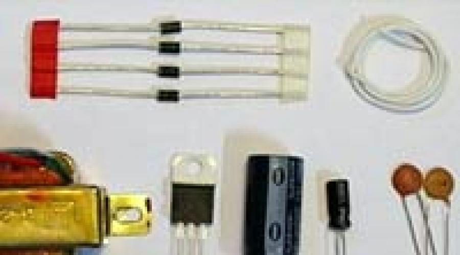
To assemble the block, prepare in advance electronic components, parts and accessories from which the block itself will be assembled ....
-Circuit board.
- Four diodes 1N4001, or similar. The bridge is diode.
- Voltage stabilizer LM7812.
- Low-power step-down transformer for 220 V, the secondary winding should have 14V - 35V AC voltage, with a load current of 100 mA to 1A, depending on how much power you need to get at the output.
- Electrolytic capacitor with a capacity of 1000uF - 4700uF.
- 1uF capacitor.
-Two 100nF capacitors.
- Cut wires.
-Radiator, if needed.
If you need to get the maximum power from the power supply, you need to prepare the appropriate transformer, diodes and heatsink for the chip.
Step 2: Tools....
For the manufacture of the block, tools for installation are required:
-Soldering iron or soldering station
-Nippers
- Mounting tweezers
-Wire strippers
- Solder suction device.
-Screwdriver.
And other tools that you might find useful.
Step 3: Schematic and more... 
To get a 5 volt stabilized power supply, you can replace the LM7812 stabilizer with the LM7805.
To increase the load capacity by more than 0.5 amperes, you will need a heatsink for the microcircuit, otherwise it will fail from overheating.
However, if you need to get a few hundred milliamps (less than 500 mA) from the source, then you can do without a heatsink, heating will be negligible.
In addition, an LED is added to the circuit to visually verify that the power supply is working, but you can do without it.

Power supply circuit 12v 30A.
When using one 7812 stabilizer as a voltage regulator and several powerful transistors, this power supply is capable of providing an output load current of up to 30 amperes.
Perhaps the most expensive part of this circuit is the power step-down transformer. The voltage of the secondary winding of the transformer must be a few volts more than the stabilized voltage of 12V in order to ensure the operation of the microcircuit. It must be borne in mind that one should not strive for a larger difference between the input and output voltage values, since at such a current the heat sink of the output transistors increases significantly in size.
In the transformer circuit, the diodes used must be designed for a large maximum forward current, approximately 100A. The maximum current flowing through the 7812 chip in the circuit will not exceed 1A.
Six composite Darlington type TIP2955 transistors connected in parallel provide a load current of 30A (each transistor is rated for a current of 5A), such a large current requires an appropriate size of the radiator, each transistor passes through itself one sixth of the load current.
A small fan can be used to cool the radiator.
Checking the power supply
When you first turn it on, it is not recommended to connect the load. We check the operation of the circuit: we connect a voltmeter to the output terminals and measure the voltage, it should be 12 volts, or the value is very close to it. Next, we connect a load resistor of 100 ohms, with a dissipation power of 3 W, or a similar load - such as an incandescent lamp from a car. In this case, the voltmeter reading should not change. If there is no 12 volt voltage at the output, turn off the power and check the correct installation and serviceability of the elements.
Before installation, check the serviceability of the power transistors, since with a broken transistor, the voltage from the rectifier goes directly to the output of the circuit. To avoid this, check the power transistors for a short circuit, to do this, measure the resistance between the collector and emitter of the transistors separately with a multimeter. This check must be carried out before installing them in the circuit.
Power supply 3 - 24v

The power supply circuit produces an adjustable voltage in the range from 3 to 25 volts, with a maximum load current of up to 2A, if you reduce the current-limiting resistor of 0.3 ohms, the current can be increased to 3 amperes or more.
Transistors 2N3055 and 2N3053 are installed on the corresponding heatsinks, the power of the limiting resistor must be at least 3 watts. Voltage regulation is controlled by the LM1558 or 1458 op amp. When using the 1458 op amp, it is necessary to replace the stabilizer elements that supply voltage from pin 8 to 3 op amps from a divider with 5.1 K resistors.
The maximum constant voltage for supplying the op-amps 1458 and 1558 is 36 V and 44 V, respectively. Power transformer should produce a voltage of at least 4 volts more than the stabilized output voltage. The power transformer in the circuit has an output voltage of 25.2 volts alternating current with outlet in the middle. When switching the windings, the output voltage decreases to 15 volts.
1.5 V power supply circuit

The power supply circuit for obtaining a voltage of 1.5 volts uses a step-down transformer, a bridge rectifier with a smoothing filter and an LM317 chip.
Regulated power supply circuit from 1.5 to 12.5 V

A power supply circuit with output voltage regulation to obtain a voltage from 1.5 volts to 12.5 volts, the LM317 microcircuit is used as a regulating element. It must be installed on the radiator, on an insulating gasket to prevent a short circuit to the case.
Fixed Output Voltage Power Supply Diagram

Power supply circuit with a fixed output voltage of 5 volts or 12 volts. The LM 7805 microcircuit is used as an active element, LM7812 is installed on a radiator to cool the heating of the case. The choice of transformer is shown on the left side of the plate. By analogy, you can make a power supply for other output voltages.
20 watt power supply circuit with protection

The circuit is for a small homemade transceiver by DL6GL. When developing the unit, the task was to have an efficiency of at least 50%, a nominal supply voltage of 13.8V, a maximum of 15V, for a load current of 2.7A.
According to what scheme: switching power supply or linear?
Switching power supplies turn out to be small-sized and the efficiency is good, but it is not known how it will behave in a critical situation, output voltage surges ...
Despite the shortcomings, a linear control scheme was chosen: a sufficiently large transformer, not high efficiency, cooling is necessary, etc.
Applied parts from homemade block power supply 1980s: radiator with two 2N3055. The only thing missing was the µA723/LM723 voltage regulator and a few small parts.
The voltage regulator is assembled on a microcircuit µA723/LM723 in standard inclusion. Output transistors T2, T3 type 2N3055 are mounted on radiators for cooling. Using the potentiometer R1, the output voltage is set within 12-15V. Using the variable resistor R2, the maximum voltage drop across the resistor R7 is set, which is 0.7V (between pins 2 and 3 of the microcircuit).
A toroidal transformer is used for the power supply (it can be any at your discretion).
On the MC3423 chip, a circuit is assembled that is triggered when the voltage (emissions) at the output of the power supply is exceeded, by adjusting R3, the threshold for the voltage operation on leg 2 is set from the divider R3 / R8 / R9 (2.6V reference voltage), voltage is supplied from output 8 to open the thyristor BT145, causing a short circuit leading to the operation of the fuse 6.3a.


To prepare the power supply for operation (fuse 6.3a is not involved yet), set the output voltage, for example, 12.0V. Load the unit with a load, for this you can connect a 12V / 20W halogen lamp. Set R2 so that the voltage drop is 0.7V (the current must be within 3.8A 0.7 = 0.185Ωx3.8).
We configure the operation of overvoltage protection, for this we smoothly set the output voltage to 16V and adjust R3 to actuate the protection. Next, we set the output voltage to normal and install the fuse (before that, we put a jumper).
The described power supply can be reconstructed for more powerful loads, for this, install a more powerful transformer, additional transistors, strapping elements, a rectifier at your discretion.
Homemade 3.3v power supply
If you need a powerful power supply, 3.3 volts, then it can be made by redoing the old power supply from the PC or using the above diagrams. For example, in a 1.5 V power supply circuit, replace a 47 ohm resistor of a higher rating, or put a potentiometer for convenience, adjusting it to the desired voltage.
Transformer power supply on KT808
Many radio amateurs still have old Soviet radio components that are lying around idle, but which can be successfully applied and they will serve you faithfully for a long time, one of the well-known UA1ZH circuits that walks around the Internet. Many spears and arrows are broken on the forums when discussing which is better field-effect transistor or ordinary silicon or germanium, what temperature of crystal heating will they withstand and which one is more reliable?
Each side has its own arguments, but you can get the parts and make another simple and reliable power supply. The circuit is very simple, it is protected from current overload and, when three KT808s are connected in parallel, it can deliver a current of 20A, the author used such a block with 7 parallel transistors and gave 50A to the load, while the capacitance of the filter capacitor was 120,000 microfarads, the voltage of the secondary winding was 19v. It must be taken into account that the relay contacts must switch such a large current.

With proper installation, the output voltage drawdown does not exceed 0.1 volts
Power supply for 1000v, 2000v, 3000v
If we need to have a high voltage constant voltage source to power the lamp of the transmitter output stage, what should we use for this? There are many different power supply circuits for 600v, 1000v, 2000v, 3000v on the Internet.
First: for high voltage, circuits are used from transformers for both one phase and three phases (if there is a three-phase voltage source in the house).
Second: to reduce the size and weight, a transformerless power supply circuit is used, directly a 220 volt network with voltage multiplication. The biggest drawback of this circuit is that there is no galvanic isolation between the network and the load, how the output is connected given source voltage respecting the phase and zero.

The circuit has a step-up anode transformer T1 (for the required power, for example, 2500 VA, 2400V, current 0.8 A) and a step-down incandescent transformer T2 - TN-46, TN-36, etc. To eliminate current surges when switching on and protecting diodes when charging capacitors, switching on through quenching resistors R21 and R22 is used.
The diodes in the high-voltage circuit are shunted by resistors in order to evenly distribute Uobr. Calculation of the nominal value according to the formula R (Ohm) \u003d PIVx500. C1-C20 to eliminate white noise and reduce surges. Bridges of the KBU-810 type can also be used as diodes by connecting them according to the indicated scheme and, accordingly, taking the right amount, not forgetting about shunting.
R23-R26 for discharging capacitors after a power outage. To equalize the voltage on series-connected capacitors, equalizing resistors are placed in parallel, which are calculated from the ratio for every 1 volt there are 100 ohms, but with high voltage the resistors are obtained with a sufficiently large power and here you have to maneuver, taking into account that the open circuit voltage is 1.41 more.
More on the topic
Do-it-yourself transformer power supply 13.8 volts 25 a for a HF transceiver.
Repair and refinement of the Chinese power supply to power the adapter.
Telemaster Secrets
B. KISELEVICH, Khatanga, Krasnoyarsk Territory
Radio, 1998, No. 4
The so-called "three-transistor" PSU is a fairly common switching power supply that was used in many models of kinescope TV sets - PHILIPS- 2021, AKAI - ST-1407, AKAI - 2107, SHERION, CROWN - STA/ 5176, ELEKTA - CTR-1498EMK, RECOR and many more.
Power supply diagram
As an example, consider such a source used in the CROWN TV - CTV5176.
The mains voltage of 220 V through the power filter is supplied to the rectifier BR601, C601 - C604 and to the demagnetization loop L2001. On the collector of the key transistor Q604, the rectified voltage passes through the winding 1-5 of the pulse transformer T601.
A blocking oscillator is made on the Q604 transistor - the positive feedback voltage is removed from the winding 7 - 8 of the transformer. The duration of the pulses generated by the blocking generator, i.e., the time the Q604 transistor is in a saturated state, is determined by the functioning of the pulse-width modulator (PWM).
A capacitor C607 is connected to the base of transistor Q604, which, during the closed state of the transistor, is charged by a voltage pulse of the winding 7 - 8 of the transformer through diode D604. When transistors Q602, Q603 are opened, the PWM capacitor C607 is connected to the emitter junction of the saturated transistor Q604, and the discharge current of the capacitor, flowing through the transistors and resistor R616, quickly closes transistor Q604. The bias voltage to the base of transistor Q604 is applied through resistors R603, R604. The C610R617 circuit limits the pulse surges at the collector of the Q604 transistor, thereby protecting it from breakdown.
To power the amplifier direct current on transistor Q601 AC voltage from winding 9 - 10 is rectified by diode D603 and charges capacitor C606. The voltage at the emitter of transistor Q601 is stabilized by a parametric stabilizer on elements D601, R609, and the voltage to the base of the transistor is taken from the measuring resistive divider R606VR601R607. The latter depends on the voltage on the winding 9 - 10 of the transformer, i.e., the output voltage levels of the power supply + 110 and + 12 V. The voltage across the resistor R608 - the collector load of the transistor Q601 serves as an error voltage and controls the opening moment of the PWM on transistors Q602, Q603. The trimmer resistor VR601 sets the output voltage to + 110 V.
A sawtooth voltage is removed from the resistor R605 through the C605R611 circuit to the base of the transistor O602 of the PWM shaper. It also receives the error voltage from the collector of transistor Q601. Depending on the last PWM, it opens earlier or later, counting from the moment Q604 opens. Transistors Q602, Q603 are analogous to a trinistor. The principle of its operation is similar to the operation of the trinistor in the pulsed power supply module MPZ-3.
With an increase in the mains voltage or a decrease in the load, the voltage on the winding 9 - 10 of the transformer T601 increases. As a result, transistors Q602, Q603 open earlier, closing the output transistor Q604 at an earlier time. This reduces the energy stored in the T601 transformer, which compensates for the increase in mains voltage.
When the mains voltage decreases, the voltage on the winding 9 - 10 of the T601 transformer will accordingly be lower. At the collector of transistor Q601, the error voltage decreases. The PWM opens at a later time, and the amount of power transferred to the secondary circuit increases to compensate for the decrease in mains voltage.
The secondary rectifiers of the block are made according to a half-wave circuit. Winding 4 - 2 transformers and elements D606, C612, L601 form a +12 V voltage source used to operate the remote control system and other low-current circuits. Winding 4 - 3 and elements D607, L602 are included in the +110 V voltage source that feeds the line scan output stage.
On transistors Q608, Q606, Q605, a unit for turning on and off the power of the horizontal scanning output stage is assembled. Thus, the TV system is turned on or off by the remote control system, that is, it is transferred to the operating or standby mode. In standby mode, transistor Q606 is closed and +110 V is not supplied to the horizontal output stage. In some TV models, relays are used for this purpose.
For repair, the block board is removed from the TV case and placed so that there is free access to the elements. In parallel with the capacitor C604, a resistor with a resistance of 220 kOhm and a dissipation power of 0.5 W is connected. Through it, the capacitor will be discharged after the TV is turned off. Solder one of the conclusions of each of the elements L601, L602, D608, C617. In this case, the load circuits of the TV will be completely disconnected from the power supply. In parallel with the capacitor C615, a 220 V and 25 W incandescent lamp is connected, which will serve as the equivalent load of the power supply.
After repair, before connecting the power supply to the TV circuits, it is imperative to check the horizontal output transistor and the secondary circuits of the horizontal transformer. Voltage is often taken from the secondary windings of the latter, rectified and smoothed to power the TV nodes. One of the reasons for the failure of the power supply may be precisely these circuits.
When selecting transistors to replace failed ones, one should be guided by their characteristics indicated in Table. 1.

Transistors 2SC1815Y can be replaced with KT3102B, 2SB774T - with KT3107B, and 2SD820, BU11F - with KT872A. The latter is mounted on a heat sink with an insulating gasket. It is permissible to replace diodes with KD209B, KD226A, KD226B.
The most typical fault
this module this is "runaway" due to a decrease in capacitance (or an increase in ESR) of electrolytic capacitors. Moreover, the reason for this trouble is not even the quality of the parts used: the main problem is that modern switching power supplies operate at high frequencies (15 kHz or even higher ...), and conventional electrolytes are simply not designed for such high frequencies and during operation they begin to heat up.
If the filter capacitor (according to the scheme, this is C606) more or less copes with its duties, then C607 works in a very difficult mode (it has to pass high-frequency pulses through itself).
Therefore, when repairing this SMPS, it is imperative to pay attention first of all to these capacitors, and to repair the unit with horizontal scanning disabled, using an incandescent lamp with a power of 60 ... 100 W as a load.
Note: the main part of the material from the Radio magazine, 1998, No. 4
M. Kireev
Modern TVs use switching power supplies, the advantages of which, compared with transformer ones, are quite well described in the literature. The power supply functionally consists of primary and secondary circuits (Fig. 1).

The power switch VT1 is either made in the form of a separate transistor, or technologically placed on a chip of a PWM controller chip.
Often, with such signs of malfunction as the front panel LED lights up for 1 ... 5 s and then goes out, clicks and whistles of the power source for 1 ... 5 s and then the TV turns off, it is impossible to reliably determine the failed functional unit TV. However, from the practice of repair, it can be argued with a high probability that such external signs are a manifestation of the failure of the following TV components:
primary power supply circuits (PWM controller, switching transistor, mains rectifier, filter capacitor, damping circuit, etc.);
secondary circuits of the power source (rectifier and protective diodes, capacitors of secondary filters, elements in loads of individual voltage sources, etc.);
power supply circuits for the horizontal scanning output stage (rectifier and filter of the horizontal scanning power supply +95 ... 140 V, horizontal scanning output transistor, horizontal transformer, etc.).
Consider a technique for detecting faults in the primary and secondary circuits of switching power supplies. Troubleshooting in a device that has the above external signs of a malfunction should begin with an external inspection of the installation. In this case, special attention should be paid to the absence of traces of burnout on the cases of power transistors and microcircuits, the integrity of the cases of oxide capacitors, the absence of signs of destruction of powerful low-resistance resistors that serve as current-limiting elements, and places of "cold" soldering of the leads of fuel elements. Sometimes visually, according to the indicated signs, it is possible to determine the nature of the malfunction that has occurred.
If visual inspection fails, proceed to the next troubleshooting step. Here you should carry out a little preparatory work, namely: either unsolder the jumpers J1, J2, J3 of the current-carrying tracks printed circuit board coming from the outputs of the rectifiers of the power supply, or, if there are none, carefully cut the current-carrying conductors in such a way that loads can be connected separately to the outputs of the power supply, which can serve as various incandescent lamps, and a laboratory power supply for the main components of the TV (Fig. 2).

The appearance of the power supply is shown in fig. 4.

At first glance, it is enough to connect the load to one rectifier, for example, feeding the horizontal output stage, in order to check this circuit as a whole, but this is not the case. Although the pulse source in this case will work steadily, it is possible to skip defects in rectifier diodes and filter capacitors of low-voltage rectifiers. This happened, for example, during the repair of the Vityaz 51ТЦ-420D TV. The TV did not turn on, however, when the power source was turned on separately with a load on the +135 V source, it worked steadily. The defect was hidden in the +12 V source filter capacitor and did not appear during operation without load.
Before turning on the power supply with loads, it is advisable to check all the rectifier diodes in the secondary and primary circuits for an open or breakdown, as well as oxide capacitors, which it is desirable to solder to check their parameters, since oxide capacitors operating in the power circuits of TVs quite often break tightness and electrolyte leaks out.
Majority modern TVs incorporate switching power supplies, the power stages of which are made either on powerful transistors or on specialized microcircuits. If the power source under test contains powerful transistor, then before connecting the power source to the network, it is necessary to check the integrity of its transitions using an ohmmeter for the absence of a break and short circuit. Possible replacements for power transistors are presented in Table. 1.
If all components, as well as the power transistor, are working, the source can be connected to the network. If the pulse source is made using a PWM controller, then due to the impossibility of checking the microcircuit with an ohmmeter, it must be connected to the network and the voltage at the PWM controller pins must be measured. The absence of one or more voltages with the remaining parts in good condition clearly indicates a faulty microcircuit, which must be replaced. Given that on some circuit diagrams of TVs, the PWM controller is drawn as a "black box" (for example, "Kolon CTK-9742") or as a circuit functional nodes("Grundic CUC 4510"), in the table. 2

The voltage values at the outputs of the most commonly used PWM controllers in television equipment are presented. Voltage values may differ from those specified by ±10%.
After checking all the parameters of the switching power supply when working on a set of loads, you can connect the source to the rest of the TV nodes by restoring the previously removed jumpers. However, before that, you need to make sure that there are no faults in the power circuits and failed elements, for example, a short circuit or open circuit of transistors in the line scan unit, and a zener diode included in the power supply circuit of the line scan output stage, as is done in some TV models, as otherwise repeated failure of the switching power supply elements is possible. Possible options for replacing imported zener diodes with domestic ones are given in Table. 3.

When replacing a zener diode, it may be necessary to select the desired specimen according to the magnitude of the stabilization voltage. Although in the vast majority of cases the TV starts working immediately after the restoration of a faulty power source, however, the connection laboratory source, similar to the author's version, allows you to control the overall performance of the TV nodes when it is impossible to quickly restore the standard power source and the current consumption of each TV node separately, since increased consumption by any node may indicate a defect, and the operation of electronic protection in any channel laboratory power supply - directly point to the node containing defective elements.
Usually, as follows from the practice of repair, if malfunctions are eliminated in pulse source power supply and other components of the TV are operational, then the device, after being connected to the network, starts to work normally, and if it has worked steadily for 20 ... 30 minutes, then the repair can be considered successful.
Little trick. After replacing the key transistor in the primary circuit of the power supply or PWM chip, before the first start, remove the mains fuse. Instead, a 60 W 220 Volt incandescent lamp is connected. After turning on, the lamp should flash brightly for the first moment, and then barely glow. This is an indicator of the correct operation of the B.P. If the lamp glows brightly all the time or does not burn at all, then the repair must be continued. This trick allows you to keep the key transistor in good condition, even if the P.P. out of order. (Krylov P.V.)
Literature
1. V.S. Moin. stabilized transistor converters. Moscow: Energoatomizdat, 1986.
[email protected]
The material in this article is intended not only for owners of already rare TVs who want to restore their performance, but also for those who want to understand the circuitry, device and principle of operation of switching power supplies. If you master the material of this article, then you can easily deal with any scheme and principle of operation of switching power supplies for household appliances, be it a TV, laptop or office equipment. And so let's get started...
On TVs Soviet-made, the third generation ZUSTST used switching power supplies - MP (power module).
Switching power supplies, depending on the TV model where they were used, were divided into three modifications - MP-1, MP-2 and MP-3-3. Power modules are assembled in the same way wiring diagram and differ only in the type of pulse transformer and the voltage rating of the capacitor C27 at the output of the rectifier filter (see circuit diagram).
Functional diagram and principle of operation of the switching power supply of the ZUSST TV

Rice. 1. Functional diagram impulse block ZUSTST TV power supply:
1 - network rectifier; 2 - trigger pulse shaper; 3 - pulse generator transistor, 4 - control cascade; 5 - stabilization device; 6 - protection device; 7 - pulse transformer of the TV power supply 3ust; 8 - rectifier; 9 - load
Let at the initial moment of time a pulse be generated in the device 2, which will open the transistor of the pulse generator 3. At the same time, a linearly increasing sawtooth current will begin to flow through the winding of the pulse transformer with terminals 19, 1. At the same time, energy will be accumulated in the magnetic field of the transformer core, the value of which is determined by the time of the open state of the pulse generator transistor. The secondary winding (terminals 6, 12) of the pulse transformer is wound and connected in such a way that during the period of accumulation of magnetic energy, a negative potential is applied to the anode of the VD diode and it is closed. After some time, the control stage 4 closes the transistor of the pulse generator. Since the current in the winding of the transformer 7 cannot change instantly due to the accumulated magnetic energy, an EMF of self-induction of the opposite sign occurs. Diode VD opens, and the current of the secondary winding (terminals 6, 12) increases sharply. Thus, if in the initial period of time the magnetic field was associated with the current that flowed through the winding 1, 19, now it is created by the current of the winding 6, 12. When all the energy accumulated during the closed state of the key 3 goes into the load, then in secondary winding reaches zero.
From the above example, we can conclude that by adjusting the duration of the open state of the transistor in a pulse generator, it is possible to control the amount of energy that enters the load. Such adjustment is carried out using the control stage 4 according to the feedback signal - the voltage at the terminals of the winding 7, 13 of the pulse transformer. The feedback signal at the terminals of this winding is proportional to the voltage at the load 9.
If the voltage at the load decreases for some reason, then the voltage that enters the stabilization device 5 will also decrease. In turn, the stabilization device through the control stage will begin to close the transistor of the pulse generator later. This will increase the time during which current will flow through the winding 1, 19, and the amount of energy transferred to the load will increase accordingly.
The moment of the next opening of the transistor 3 is determined by the stabilization device, which analyzes the signal coming from the winding 13, 7, which allows you to automatically maintain the average value of the output DC voltage.
The use of a pulse transformer makes it possible to obtain voltages of different amplitudes in the windings and eliminates the galvanic connection between the circuits of secondary rectified voltages and the power supply network. Control stage 4 determines the range of pulses generated by the generator and, if necessary, turns it off. The generator is turned off when the mains voltage drops below 150 V and the power consumption drops to 20 W, when the stabilization stage ceases to function. When the stabilization stage is not working, the pulse generator turns out to be uncontrollable, which can lead to the occurrence of large current pulses in it and to the failure of the pulse generator transistor.
Schematic diagram of the switching power supply of the ZUSST TV
Consider the schematic diagram of the MP-3-3 power supply module and the principle of its operation.

Rice. 2 circuit diagram switching power supply unit for ZUSCT TV, MP-3-3 module
It includes a low-voltage rectifier (diodes VD4 - VD7), a trigger pulse shaper (VT3), a pulse generator (VT4), a stabilization device (VT1), a protection device (VT2), a pulse transformer T1 of the 3ust power supply and rectifiers on VD12 diodes - VD15 with voltage regulator (VT5 - VT7).
The pulse generator is assembled according to the blocking generator circuit with collector-base connections on the VT4 transistor. When the TV is turned on, a constant voltage from the output of the low-voltage rectifier filter (capacitors C16, C19 and C20) through the winding 19, 1 of the transformer T1 is supplied to the collector of the transistor VT4. Simultaneously mains voltage from the VD7 diode through the capacitors C11, C10 and the resistor R11 charges the capacitor C7, and also enters the base of the transistor VT2, where it is used in the device for protecting the power supply module from low mains voltage. When the voltage on the capacitor C7, applied between the emitter and base 1 of the unijunction transistor VT3, reaches a value of 3 V, the transistor VT3 will open. Capacitor C7 is discharged through the circuit: emitter-base junction 1 of transistor VT3, emitter junction of transistor VT4, connected in parallel, resistors R14 and R16, capacitor C7.
The discharge current of the capacitor C7 opens the transistor VT4 for a time of 10 - 15 μs, sufficient for the current in its collector circuit to increase to 3 ... 4 A. The flow of the collector current of the transistor VT4 through the magnetization winding 19, 1 is accompanied by the accumulation of energy in the magnetic field of the core. After the end of the discharge of the capacitor C7, the transistor VT4 closes. The cessation of the collector current causes the appearance of an EMF of self-induction in the coils of the transformer T1, which creates positive voltages at terminals 6, 8, 10, 5 and 7 of the transformer T1. In this case, current flows through the diodes of one-half-wave rectifiers in the secondary circuits (VD12 - VD15).
With a positive voltage at the terminals 5, 7 of the transformer T1, the capacitors C14 and C6 are charged, respectively, in the anode and control electrode circuits of the thyristor VS1 and C2 in the emitter-base circuit of the transistor VT1.
Capacitor C6 is charged through the circuit: terminal 5 of transformer T1, diode VD11, resistor R19, capacitor C6, diode VD9, terminal 3 of the transformer. Capacitor C14 is charged through the circuit: terminal 5 of transformer T1, diode VD8, capacitor C14, terminal 3 of the transformer. Capacitor C2 is charged through the circuit: terminal 7 of transformer T1, resistor R13, diode VD2, capacitor C2, terminal 13 of the transformer.
Similarly, subsequent switching on and off of the transistor VT4 of the blocking generator is carried out. Moreover, several such forced oscillations are sufficient to charge the capacitors in the secondary circuits. With the end of the charging of these capacitors between the windings of the blocking generator connected to the collector (pins 1, 19) and to the base (pins 3, 5) of the transistor VT4, a positive Feedback. In this case, the blocking generator goes into self-oscillation mode, in which the VT4 transistor will automatically open and close at a certain frequency.
During the open state of the transistor VT4, its collector current flows from the plus of the electrolytic capacitor C16 through the winding of the transformer T1 with terminals 19, 1, the collector and emitter junctions of the transistor VT4, resistors R14, R16 connected in parallel to the minus of the capacitor C16. Due to the presence of inductance in the circuit, the increase in the collector current occurs according to a sawtooth law.
To eliminate the possibility of failure of the transistor VT4 from overload, the resistance of the resistors R14 and R16 is selected in such a way that when the collector current reaches a value of 3.5 A, a voltage drop is created across them sufficient to open the thyristor VS1. When the thyristor is opened, the capacitor C14 is discharged through the emitter junction of the transistor VT4, resistors R14 and R16 connected in parallel, an open thyristor VS1. The discharge current of the capacitor C14 is subtracted from the base current of the transistor VT4, which leads to its premature closing.
Further processes in the operation of the blocking generator are determined by the state of the thyristor VS1, the earlier or later opening of which allows you to control the rise time of the sawtooth current and thereby the amount of energy stored in the transformer core.
The power module can operate in stabilization and short circuit modes.
The stabilization mode is determined by the operation of the UPT (DC amplifier) assembled on a VT1 transistor and a VS1 thyristor.
At a mains voltage of 220 volts, when the output voltages of the secondary power sources reach the nominal values, the voltage on the winding of the transformer T1 (terminals 7, 13) increases to a value at which the constant voltage at the base of the transistor VT1, where it enters through the divider Rl - R3, becomes more negative than at the emitter, where it is completely transmitted. Transistor VT1 opens in the circuit: terminal 7 of the transformer, R13, VD2, VD1, emitter and collector junctions of the transistor VT1, R6, control electrode of the thyristor VS1, R14, R16, terminal 13 of the transformer. This current, summing up with the initial current of the control electrode of the thyristor VS1, opens it at the moment when the output voltage of the module reaches the nominal values, stopping the increase in the collector current.
By changing the voltage at the base of the transistor VT1 with a trimmer resistor R2, you can adjust the voltage across the resistor R10 and, therefore, change the opening moment of the thyristor VS1 and the duration of the open state of the transistor VT4, thereby setting the output voltages of the power supply.
When the load decreases (or the mains voltage increases), the voltage at the terminals 7, 13 of the transformer T1 increases. This increases the negative voltage at the base with respect to the emitter of the transistor VT1, causing an increase in the collector current and a voltage drop across the resistor R10. This leads to earlier opening of the thyristor VS1 and closing of the transistor VT4. This reduces the power delivered to the load.
When the mains voltage decreases, the voltage on the winding of the transformer T1 and the potential of the base of the transistor VT1 with respect to the emitter become correspondingly smaller. Now, due to a decrease in the voltage created by the collector current of the transistor VT1 on the resistor R10, the thyristor VS1 opens at a later time and the amount of energy transferred to the secondary circuits increases. An important role in the protection of the transistor VT4 is played by the cascade on the transistor VT2. When the mains voltage drops below 150 V, the voltage on the winding of the transformer T1 with terminals 7, 13 is insufficient to open the transistor VT1. At the same time, the stabilization and protection device does not work, the VT4 transistor becomes uncontrollable and it becomes possible for it to fail due to exceeding the maximum allowable values of voltage, temperature, current of the transistor. To prevent the failure of the transistor VT4, it is necessary to block the operation of the blocking generator. The transistor VT2 intended for this purpose is turned on in such a way that a constant voltage is supplied to its base from the divider R18, R4, and a pulsating voltage with a frequency of 50 Hz is applied to the emitter, the amplitude of which is stabilized by the zener diode VD3. When the mains voltage decreases, the voltage at the base of the transistor VT2 decreases. Since the voltage at the emitter is stabilized, a decrease in the voltage at the base leads to the opening of the transistor. Through the open transistor VT2, trapezoidal pulses from the VD7 diode arrive at the control electrode of the thyristor, opening it for a time determined by the duration of the trapezoidal pulse. This leads to the termination of the blocking generator.
The short circuit mode occurs when there is a short circuit in the load of secondary power supplies. In this case, the power supply is started by triggering pulses from the start-up device assembled on the VT3 transistor, and turning off is done using the VS1 thyristor according to the maximum collector current of the VT4 transistor. After the end of the trigger pulse, the device is not excited, since all the energy is consumed in a short-circuited circuit.
After removing the short circuit, the module enters stabilization mode.
Impulse voltage rectifiers connected to the secondary winding of the transformer T1 are assembled according to a half-wave circuit.
The rectifier on the VD12 diode creates a voltage of 130 V to power the horizontal scanning circuit. The smoothing of the ripples of this voltage is produced by an electrolytic capacitor C27. Resistor R22 eliminates the possibility of a significant increase in voltage at the rectifier output when the load is disconnected.
A 28 V voltage rectifier is assembled on the VD13 diode, designed to power the vertical scan of the TV. Voltage filtering is provided by capacitor C28 and inductor L2.
15 V voltage rectifier to power the amplifier audio frequency assembled on a VD15 diode and a SZO capacitor.
The voltage of 12 V used in the color module (MC), the radio channel module (RTO) and the vertical scanning module (MK) is created by a rectifier on the VD14 diode and capacitor C29. At the output of this rectifier, a compensating voltage regulator assembled on transistors is included. It consists of a regulating transistor VT5, a current amplifier VT6 and a control transistor VT7. The voltage from the output of the stabilizer through the divider R26, R27 is supplied to the base of the transistor VT7. Variable resistor R27 is designed to set the output voltage. In the emitter circuit of the transistor VT7, the voltage at the output of the stabilizer is compared with the reference voltage at the zener diode VD16. The voltage from the collector VT7 through the amplifier on the transistor VT6 is fed to the base of the transistor VT5, connected in series to the rectified current circuit. This leads to a change in its internal resistance, which, depending on whether the output voltage has increased or decreased, either increases or decreases. Capacitor C31 protects the stabilizer from excitation. Through the resistor R23, voltage is supplied to the base of the transistor VT7, which is necessary to open it when turned on and recover after a short circuit. Inductor L3 and capacitor C32 - an additional filter at the output of the stabilizer.
Capacitors C22 - C26 shunt rectifier diodes to reduce interference emitted by pulse rectifiers into the electrical network.
Surge protector of the power supply ZUSTST
The FFP power filter board is connected to electrical network through connector X17 (A12), switch S1 in the TV control unit and mains fuses FU1 and FU2.
As mains fuses, fuses of the VPT-19 type are used, the characteristics of which make it possible to provide much more reliable protection television receivers in the event of malfunctions than fuses of the PM type.
The purpose of the barrier filter is .
On the power filter board there are elements of the surge filter (C1, C2, NW, inductor L1) (see schematic diagram).
Resistor R3 is designed to limit the current of the rectifier diodes when the TV is turned on. The posistor R1 and the resistor R2 are elements of the kinescope mask demagnetization device.