LIMP Arta Software is a software RCL meter. Homemade measuring instruments Rcl DIY digital meter
Read also
I will continue the description of the LIMP program from the company's package Arta Software
. With its help, you can determine the values of resistances, inductances, capacitances. A computer is sufficient for this. free program and hardware from one resistor and several cords.
Of course, this meter cannot replace specialized devices either in terms of convenience or measurement accuracy, but it is not always advisable to buy an expensive device for the sake of several measurements. The proposed instrument is purely amateur radio - measurements are slow and require some work of the brain and hands, but for free and with your own hands.

Hardware

Of the parts you need 2 3.5 mm connectors for sound card with shielded wires, a resistor of about 100 ohms, a switch with one group of contacts (or analog button) any, two alligator clips or clips.
I was interested in digging myself. ARTA writes that for accuracy it is desirable that Z be less than 100 ohms, much less than the input impedance of the sound card (allegedly it is about 20 kOhm). I think that very low Z when measured is very large containers, also worsens accuracy, but in practice it is of little interest - the capacitance is 20,000 microfarads or 22,000 microfarads, it is more important to know that this capacitance exists, has not dried up, and if there is a need to select identical capacitances, then the absolute value is also not so important. I remind you again - see the result with a phase for capacitors of about -90, and inductances +90. By the way, for capacitors with poor thermal dependence, you can see how Z changes from the heat of the fingers.
You can check the ancient containers from stocks (ESR is not visible, which is a pity), the drop of the container due to drying out or breakage is immediately visible.
No words, special devices are 1000 times better, but they cost money and take up space.
Resistance measurements
At first, I even wanted to omit this item - everyone has cheap digital Chinese testers, but after thinking, I found cases when this method may be useful.This is a measurement of low resistances - up to 0.1 Ohm inclusive. First you need to calibrate the device and close its probes. With a long cord, I got 0.24 ohms. This value will be subtracted from all measurements of low-resistance resistors. I have a handful of C5-16MV-5 3.9 ohm resistors with 1% accuracy.

All tested resistors gave this result. 4.14 - 0.24 = 3.9
A handful of other low-resistance resistors were measured for verification, without comment. The lowest resistance was at 0.51 Ohm + - 5%. Measured value 0.5 ohm. Unfortunately, I could not find 0.1 Ohm in my stocks, but I am sure that there would be no problems with them either, only clips with good contacts are needed.
In addition to measuring the resistance of low-resistance resistors, interest, especially for filters acoustic systems, represents their inductance. They are wire, wound in a coil. How significant is their inductance? I checked mostly low-resistance (up to 20 ohms) resistors (they don’t put high-resistance in acoustics and amplifiers) of types C5-16MV, C5-37V, C5-47V, PEVR-25, C5-35V. Their inductance was in the range of 2…6 microHenry. When measuring resistors of hundreds of ohms, their inductance was an order of magnitude higher.
Inductance measurements
Smoothly we pass to inductances. I do not have now precise inductances, so I just checked the qualitative, but not quantitative performance of the method.
These are measurements of the DM-0.1 inductor at 30 μH, it turned out to be plausible.

Here is a choke from a switching power supply. It also seems to be true. I can't vouch for accuracy - there is room for research here.
Capacitance measurements
The most interesting part, there is something incomprehensible, but the results are very interesting. Measurement range from 0.1 uF to 100,000 uF. Accuracy - a few percent. More or less tolerable results are obtained from 0.01 uF, but measurements at low frequencies a long cord with a large capacity is of little use. I proceeded from the fact that capacitances of the order of fractions of microfarads are of interest for acoustic system filters and tone controls, ULF isolation capacitors. There was a hope to see ESR (did not come true). Since I did not find any precision containers, I had to use the statistical method and common sense. At first I made and wanted to present a large table, but then the obvious truth came to me, only the results for you.
This is a 0.15 MKP X2 capacitor. At what frequency to measure? Arta covers it indistinctly. They say that you need to measure at an impedance of less than 100 ohms (one cell on the graph on the left is 800 ohms) ...
At 200 Hz, 0.18 uF is obtained, at 20 kHz - 0.1 uF. From the basics of electrical engineering, it is known that the current in the capacitance is ahead of the voltage (-90 degrees), in the inductance - on the contrary (+90 degrees), so we are guided by the gray curve and the phase shift number on the right. It is better if the shift is close to 90 degrees. Unfortunately, due to the limited frequency range, this does not always work out, in addition, often around 20 kHz the phase shift decreases, we will not climb into this area!

Here is an example. This is a non-polar oxide capacitor 2.2uF at 15V. There is a strong suspicion of its low quality and unsuitability for audiophiles. For non-electrolytic capacitors with a higher voltage, the phase graph is different. Here, the most reliable results are in the region of 0.5…1 kHz.

Capacitor 1 uF K10-47V for 50 V TKE H30. Reliable and stable result in the frequency range of 1…20 kHz with a phase shift of 85…90 degrees.
Curiosity pulled me to look: what will happen if you measure oxide (electrolytic) capacitors? It turned out that you can measure! The result is absolutely independent of the polarity of the connection, I even measured 4 banks of 10,000 microfarads connected in parallel and got a reliable result. I can judge the reliability because before that I measured dozens of capacitors from 1 to 15,000 microfarads.

It turned out 44 milliFarads. Pay attention to the phase response in the region of several kHz, it takes on the character of an inductance. What is it - the imperfection of the instrument, or is it really that at such frequencies the capacitance of the plates works worse, and the inductance of the winding roll speaks louder and louder? Parallel connection small film capacity did not affect the graph.
Due to the fact that the loading of graphics in the post is limited, I give a minimum of examples, so I’ll just repeat that you need to measure at the most “correct” phase (when you go through 0, you will get “inductance” from the capacitance and vice versa).

Sometimes it happens. This is one of the old soldered oxide tanks. Clearly, she belongs in a landfill. Can you imagine what such a capacity will do with sound ?!
It is possible to fall into such a trap.
I have been using a homemade capacitance and ESR capacitor meter for quite a long time, assembled according to the scheme from the GO author from the ProRadio forum. Along the way, in my use there is another equally popular FCL meter from the cqham website.
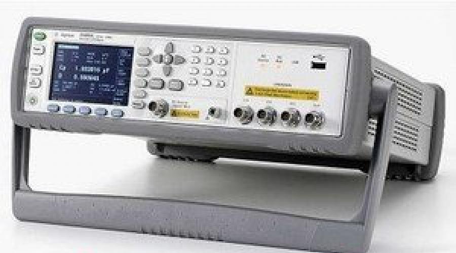
Today in the review is a device that has a higher declared accuracy, as well as actually combining both of the above devices.
Attention, a lot of photos, little text, can be critical for users with expensive traffic.
It is probably worth starting with the fact that this device is also sold in full, i. already assembled. But in this case, the designer was chosen purposefully, since at least it allows you to save a little money, and at the most, just enjoy the assembly. And perhaps the second is more important.
In general, I have long wanted to change the previous model C-ESR meter. In principle, it works, but after at least one repair, it began to behave not quite adequately when measuring ESR. Since I work a lot with impulse blocks power supply (although this is true for ordinary ones), then this parameter is even more important for me than just capacity.
But in this case, we are not dealing with just a C-ESR meter, but with a device that measures ESR + LCR, but full list measured values looks even more, in addition, a good accuracy is also declared.
Inductance 0.01uH - 2000H (10uH)
Capacitance 200pF - 200mF (10pF) Resolution 0.01pF
Resistance 2000mΩ- 20MΩ (150mΩ) Resolution 0.1mΩ
Accuracy 0.3 - 0.5%
Test signal frequency 100 Hz, 1 kHz, 7.831 kHz
Test voltage 200 mV
Automatic calibration function
Output impedance 40 ohm
The instrument can measure
Q - quality factor
D - Loss factor
Θ - Phase angle
Rp - Equivalent parallel resistance
ESR - Equivalent Series Resistance
Xp - Equivalent parallel capacitance
Xs - Equivalent series capacitance
Cp - Parallel capacitance
Cs - Series capacitance
Lp - Parallel inductance
Ls - Series inductance
In this case, the measurement is carried out by the bridge method using a four-wire connection of the component.
In my opinion, the closest competitor is the E7-22, but it has a lower stated measurement accuracy (0.5-0.8%), a test frequency of only 120 Hz and 1 kHz and a test voltage of 0.5 Volts against 0.3% , 120 Hz - 1 kHz - 7.8 kHz, 0.2 Volta at the surveyed.
for sale this device in several configurations, the review uses almost the most complete version. Prices from the seller's page.
1. Only the device itself without a case - $21.43
2. Device + one type of probes - $25.97
3. Device + second type of probes - $26.75
4. Device + two types of probes - $31.29
5. Case to the device. - $9.70 
Everything was packed in a bunch of small packages. 
Since when delivering through an intermediary, the weight of the package is usually taken into account, I additionally decided to weigh it, 333 grams came out without cables, noticeably more with cables, 595 grams.
In general, it is quite possible to buy without cables, especially if you have something to make them yourself, since the difference only in the price of the kit comes out to about $ 10, not counting the weight. 
By the way, I'll start with the cables.
Packed in separate packages, even just feels like a decent weight. 
The first set is essentially ordinary "crocodiles", but larger size and in plastic. But in fact, not everything is so simple, the sponges are connected to different wires (connectors) in order to implement the correct four-wire connection.
The cable is moderately flexible, the rigidity is rather added by the fact that there are four cables, while they are shielded. The probes are connected to the device itself using conventional BNC connectors, the screen is connected only on the side of the BNC connector.
There are no complaints about the quality, the only thing that I didn’t really like was the lack of color marking near the connectors, since the crocodiles themselves have it. As a result, to connect, you need to look every time which one we connect to. The solution is to make a mark with electrical tape near the connectors. 
But the second set is much more interesting, it allows you to work with small components, as it is a pair of tweezers.
The photo shows that the central cores of the wires are connected not at the ends of the tweezers, but at a certain distance, i.e. this option is slightly worse than the previous one, but it is also more difficult to implement a system like that of “crocodiles”. There is no color marking.
For ease of use, the tweezers have a guide that protects the sponges from shifting relative to each other. I don’t know how long they will last, but for now it’s quite convenient to use, although there is a remark - you need to squeeze closer to the sponges themselves, if you squeeze the tweezers near the middle of the body, then the sponges may not converge completely. 
Just a few words about what it is in general - a four-wire connection or a Kelvin connection. Pictures taken, text mine :)
The principle of measuring resistance is quite simple. Connect the component to a current source and measure the voltage across the component. But since we have the resistance of the wires, we will end up with a sum consisting of the real resistance of the component and the resistance of the wire.
If the resistance is large, then usually this does not play a special role, but if we are talking about values of 1-10 ohms and less, then the problem climbs to its full height.
To solve this problem, the circuits through which the current flows through the component and the circuits directly measuring are separated. 
In real life, it looks something like the one shown in the diagram. 
In addition, a similar method is used, for example, in power supplies. For example, a photo from my review of a powerful converter. Here you can also separate the power circuit and the circuit feedback, then the voltage drop on the wires will not affect the voltage on the load.
You also probably saw something similar in computer power supplies along a 3.3 Volt circuit (orange wires). only there a three-wire circuit was used (the same additional thin wire to the power socket) 
Power supply 12 Volt 1 Amp, outwardly not bad. However, I tried to connect it and just to the load, it works fine.
But because of the plug with flat pins, it is inconvenient to use it, I will replace it with something else, since the voltage is standard.
In reality, the device can be powered by a voltage of 9-15 volts.
It’s a pity that you can’t choose a complete set without a power supply unit, I think that many radio amateurs can find such a power supply unit at home. 
The main body of the kit has been split into three separate packages. 
One of them has the most common 2004 display (20 characters, 4 lines) with backlight. 
The board of the device was carefully wrapped with an "air" film. 
Here is just the case when in the photo in the store the fee seems to be less than it really is :)
The actual dimensions are 100x138mm. 

The front part of the board takes up space for probe connectors. 
The middle part is the measuring unit, switches, operational amplifiers. Apparently, the screening of this node was supposed, but the screen itself is not included in the kit. 
At the top of the "brains" and nutrition. 
In the first versions of the device, linear power stabilizers were used, in this version they are replaced by pulse ones.
Also visible is the connector for connecting the power supply and the switch.
Replacing stabilizers with switching ones can significantly help with battery power. For example, included with aluminum case Comes with a cassette for 3 18650 batteries. 
Everything is controlled by a microcontroller. It is based on the old 8051 core and has an eight-channel 10-bit ADC on board. In the first versions of the device, it was in a DIP-40 package, in new versions it was replaced by an SMD version. 
The board also has a connector for connecting to a programmer. 
A few individual photos of installed components. 
The bottom is empty, only the screen soldering points and the control points of the outputs of stabilizers and power converters are displayed here. 
Well, the last bag, with radio components, which actually will still need to be installed on the board. 
This includes the keyboard board, as well as all sorts of resistors, capacitors, connectors, etc.
In general, the design is quite thought out, small components are already soldered on the board, only larger ones need to be installed and soldered. Those. the element of "assault" is preserved, but at the same time there is no masochism for novice radio amateurs in terms of soldering small components, and it's much more difficult to screw up. As a result, you can quickly assemble the device and get a positive impression of the process. 
The components are arranged in bags, but mostly several denominations in one package. 
All resistors included in the kit are precision. At the initial stage, just in case, I measured their real resistance.
It helps in the assembly that there are few denominations, but at the same time they are also easily measured even with a cheap tester, since there are no resistors too close to each other at face value.
At the top, what needs to be soldered, there are essentially only six denominations - 40 Ohms, 1, 2, 10, 16 and 100 kOhms.
At the top are the resistors from the signed package, they are not soldered to the board, but are used to test and calibrate the device. At first I thought that they should be soldered to some important places, which is why I measured the resistance. But then it turned out that they were “superfluous”, and the number (16 pieces) of installed resistors coincided with the number that were in the first package. 
The kit includes capacitors with ratings - 3.3, 10, 22, 47 nF, 0.1, 0.2 and 0.47uF.
In the photo below, I marked the capacitors as they are marked on the board. 
In addition, connectors, a pair of electrolytic capacitors, a relay and a buzzer are additionally installed. 
While I was waiting for my parcel, I searched the Internet for extended information about the device. It turned out that there is not only a scheme, but also different versions printed circuit board, firmware, and indeed quite a lot of people are involved in this model.
The scheme is of course rather conditional, but it gives a general understanding. 
But along the way, I remembered that about 8-9 years ago, in my own city, a person was developing. If you look at the diagram, you can see a lot in common, and it was developed before the monitored one. 
The seller's comment on the product page really cheered me up, sorry for the Google translation.
IN simple form(well, very exaggerated) it means - I check all the boards, send them to great shape, so you don’t need to send me your crafts, soldered with a hot nail on the knee with orthophosphor instead of flux.
Love your board and treat it like your favorite friend :) 
It is worth noting that both the quality of the board manufacturing and the soldering of the components are 5 points. Everything is not only neatly soldered, but also thoroughly washed!
At the same time, all installation places are marked and have both a reference designation and an indication of the component rating. Honestly, 5 points. 
Video of unpacking and description of the kit.
Let's move on to assembly. In general, when I opened all these packages and laid them out on the table, I really wanted to immediately sit down and solder this design, the only thing that stopped me was that it was decided to make some small instructions for assembly, if one of the beginners decides to do it.
First of all, we pour the resistors on the table and find the ones that are the most, these are the ratings of 2 and 10 kOhm. 
We install and solder them first. This will allow you to quickly remove most of the free seats from the board and make it easier to find the remaining ones later. 
I understand perfectly well that my instructions are completely for beginners, so I'll hide the rest of the assembly under the spoiler.
Assembly of the device board.
We do the same with the rest of the resistors, since there are few of them left. 

With capacitors, the situation is similar, first we solder the 10nF capacitors (103), since there are most of them. 

Then the ratings are 0.1 and 0.22 uF (104 and 224). 

Well, a few more capacitors, literally 1-2 of them. 

It is extremely difficult to install relays and connectors incorrectly, the tweeter has a + symbol both on the board and on the tweeter itself (a long lead is a plus).
A pair of electrolytic capacitors is also unlikely to cause problems, there is one of each rating, a minus (short terminal) is indicated on the board in white. 

BNC connectors soldered surprisingly well. In general, for the entire assembly time, I did not use flux, it was enough that I was in solder. 
The final touch, the installation of racks. Here, everyone is doing their own thing.
In general, I did not quite understand why there are 16 racks in the kit. 8 long ones are needed to install the keyboard and indicator board, let's say 4 short ones from the bottom or top, but why 8? 
As a result, I did it my way, 8 long ones are on top of the board, and 4 short ones are on the bottom. This option allows you to more conveniently use the board temporarily without a case. In this case, the upper indicator posts are screwed up, and the short ones are screwed into them. 
A couple of photos of the soldered board for control. 

After assembly, we get a pretty beautiful printed circuit board, the main thing is not to confuse anything in the process :) 
I molded the leads of the resistors with a small tool, but it turned out that the distance between the leads is a little more than necessary. In the end, I decided to raise the resistors a little above the board, but rather for beauty, at least I like it better. 
After soldering, be sure to wash the board, since there was not enough flux, I managed with alcohol. 
After assembly, I noticed that the board can be slightly shortened from the base 138mm. Approximately up to 123-124mm if you leave the programming connector or up to 114mm if you cut it out too. In this case, the probe connectors are connected by wires to specially designed holes. Perhaps it will be useful when "packing" in a small case. 
Only buttons are located on the keyboard board, and they accidentally gave not 8, but 9 buttons. One button "stuck" with another. 
But they didn’t put one “comb” in the kit, I had to gut the “gasket” a little, and at the same time I took out the mate parts.
True, in my case there were only corner connectors, but a lot :)
In general, it is useful to have a set of such connectors on the farm, they often help out. 
Solder the connectors to the keyboard board and indicator. By the way, the keyboard connection is implemented fully, ie. each button has its own processor output, and not the use of resistors and ADC, as is sometimes the case. 
That's all, the kit is completely ready. 
When assembled, the layout resembles a multimeter, with an indicator on top, buttons below, and connectors even below. 
As you can understand from what I wrote above, this is the second version of the device, essentially modified. But I like the version of the case more from previous version and plans to do just such a variant of the case. True, such a case costs about 9-10 dollars, and if you buy with a keyboard board and a front panel, then even more. By the way, I already had a review of such a case, where I assembled in it adjustable block nutrition. 
My version is designed for installation in an aluminum case. 
And as planned, it should look like in this photo. But let's just say that design is more individual, I came across various options on the Internet. 
After assembly, I still had test resistors, a button and some fasteners. Well, the power supply with probes of course. 
Now we turn to the description of the capabilities of the device and the specifics of its operation.
When turned on, a welcome message, then a basic operating screen. By the way, everything worked right away, there are no tuning elements in the device at all, I assembled it - turned it on - use it.
If after assembly the device works for you, but does not measure correctly (or does not measure at all), you must reset the calibration settings to the factory settings.
Press and hold the "M" button to get into the menu (maybe it works from the second press).
Press the "RNG" button to enter the calibration menu.
Press the "C" button five times to reset the settings.
Press the "L" button to save your changes.
Next, return to the menu by holding the "M" button.
Press the "X" button to exit the menu

The device can operate in four main modes:
1. Automatic selection. Here the device itself determines what to measure. The choice is made according to the prevailing value. Those. if the component has a capacitive component, it will switch to the capacitance measurement mode, if it is inductive, then to the inductance measurement mode. Sometimes it can be wrong, especially if the component has several pronounced components, for example, some resistors can be defined as an inductance.
To help automation added manual selection -
2. Capacitance measurement
3. Inductance
4. Resistance.
The indicator also displays the frequency of the test signal and the measurement limit. The measurement limits are somewhat “non-standard” and include as many as 16 pieces - 1.5, 4.5, 13, 40, 120, 360 Ohm. 1, 3, 9, 10, 30, 90, 100, 300, 900 kΩ and 2.7 MΩ.
By default, the device starts at automatic mode measurements at a frequency of 1 kHz. 
A little about management.
There are eight buttons under the indicator, it is signed.
M- Menu, from here they make the necessary calibrations and reset the settings to the factory settings.
RNG- Range. In a menu, this button gives access to the calibrations submenu.
WITH- Fast automatic calibration.
L- Switching the display mode (first photo). In the menu - memory
X- Switching the operating modes of the device. In menu mode - exit.
R- Decrease value in calibration mode (X-increase)
Q- mode of relative measurements. Can be used to match two identical components. we connect the exemplary component, press the button, disable the exemplary component and connect the selected ones. The percentage discrepancy will be displayed on the screen (second photo).
F- Frequency selection 100Hz - 1kHz - 7.8kHz. 
Device menu view. 
The quick calibration mode by pressing button C has two options:
1. When measuring capacitance and inductance, it is made with open probes.
2. When measuring resistance - with closed. In both versions, the device self-calibrates three times for each frequency.
3, 4. Calibration in resistance mode, you can see the resistance of the probes before and after calibration. 
In the mode of measuring low resistances, calibration is quite important, since the capabilities of the device allow you to even “see” the resistance of the capacitor leads, not to mention different wires. 
All sorts of other tests.
Naturally, in this mode it is convenient to measure the resistance of low-resistance resistors, as well as such “non-standard” measurements as the resistance of button contacts, relays or connectors. 
In terms of resistance measurement accuracy, the device can compete with my Unit 181. 
When measuring inductance, the device also behaved quite well. In the photo, the inductance is 22 μH and three tests with different frequencies of inductance with a nominal value of 150 μH. 
Now you can move on to the main thing, in fact, for which I mainly need it, measuring the parameters of capacitors.
At first I just poked different capacitors and looked at what it shows, but one (or rather a couple) surprised me.
I measured a couple of identical capacitors that were soldered from old (about 20 years old) Hungarian or Czechoslovak equipment. One showed 488uF, and the second almost 600. Everything would be fine, but initially these are 470uF 40 Volt capacitors.
Moreover, they behave differently at a frequency of 7.8 kHz. Rather, the difference in capacitance is not proportional to each other. 
Then I took another capacitor (like Matsushita), bought a long time ago, but still lying in the throttle.
The instrument was able to measure capacitance normally at 100 Hz and 1 kHz, but at high frequency capacity displayed somewhat incorrectly. In general, at a frequency of 7.8 kHz, the device sometimes behaves a little strange, sometimes overestimating the capacitance relative to the first two frequencies. Sometimes (when measuring capacitive capacitors) it falls into the ----OL---- mode or shows an excess of more than 20mF.
By the way, the resolution of the device allows you to even see the difference in the place of connection to the output. Even on the example of one output, you can see how the internal resistance changes. This is me, in fact, to the fact that I am sometimes asked, but you can connect a capacitor on the wires if it does not fit into place. You can connect, but the performance will decrease slightly. 
As you understand, it is not interesting to simply measure capacitors, so I asked a friend for his E7-22. Along the way, I noticed that even instrument control has a lot in common. 
The first step was film capacitors. Below is a precision 1% capacitor with a declared capacitance of 0.39025 uF. 
1, 2. 100uF polymer capacitor
3, 4. But with the measurement of large capacities, the E7-22 has problems. The monitored device measures a capacitance of 10,000 microfarads at a frequency of 1 kHz without any problems, E7-22 even at 4700 already gave me an overload. 
1, 2. Capxcon KF series 330uF.
3, 4. Capacitor of the same company (allegedly), just lying in a box for several years and swollen. 
And this is just out of curiosity. A couple of capacitors from my old motherboard, which worked 24/7 for about 10 years.
1. 2200uF
2. 1000uF
The capacitance at the first capacitor has dropped noticeably, but the internal resistance is in order. More often it happens the other way around, the capacitance remains the same, and the internal resistance increases. 
Video of the work process and tests.
If you have any more suggestions for tests, then while I have two devices on hand at once, I could experiment. It occurred to me only to check the scope of the test signal.
Shown below is the range of the test signal relative to ground. The top two are viewed at 100 Hz and 7.8. kHz, lower - E7-22 at frequencies of 120 Hz and 1 kHz. The difference is about 2.5 times. 
Above, I wrote that I plan to use a case where the indicator is not parallel to the surface, but perpendicular.
But in the process it turned out that the indicator, although applied and relatively good, is focused precisely on what will be viewed from the front or front-bottom. 
At large angles, and even more so when viewed from above or from the side, the image disappears or begins to invert. 
Actually, that's why I decided to finally try a display made using VATN technology. In general, I wanted OLED, I already did it, but it’s almost impossible to buy 2004, and as it turned out later, VATN is also sold in few places online.
As a result, I had to go to our offline store and buy there.
There were three models to choose from, with blue, green and white font, I liked it better with white, the model is , the price is about 15-16 dollars, . Produced by WINSTAR.
At first glance, the indicators differ little from each other, at least the size of the board is completely identical - 98x60 mm. 
More details about the indicator and connection nuances
Below there is a slight difference, but seemingly insignificant. 
The new indicator is about 0.5mm thinner. 
The general connection principle is almost the same, with the exception of a few nuances, which I will discuss below. 
For starters, the difference is that VATN displays need negative voltage to adjust the contrast, so the board has a voltage converter based on the well-known 7660, which I also reviewed.
Nearby there is a place for a tuning resistor. The middle output goes to the contrast adjustment contact, the other two to + 5 and - 5 Volts, respectively. 
At first I wanted to install a trimming resistor, giving full control to the indicator board, but then I decided not to bite out the extra pin of the connector and simply turned on the resistor so that one pin went to the standard output of the contrast adjustment (number 3 on the common connector), and the second to the output of negative 5 Volt.
I adjusted the image, soldered the tuning resistor, it turned out that I needed a constant resistor with a resistance of 2.6 kOhm, the closest one at hand was 2.49 kOhm, and I soldered it already “stationary”. 
But that wasn't all.
And now Attention, The 15th pin of the connector for conventional indicators is the positive backlight output, here it is the negative voltage output and in no case can you just change the indicator one to another, in the end you will just burn it.
I did it a little differently, out of 16 contacts I soldered only 14.
Pin 16 is the minus of the backlight, and the plus is connected to the input +5 Volts, so I just threw a jumper between the minus of the backlight and the common wire of the indicator board.
And here attention second time!
Initially, I thought to just leave pin 16 in place, since the usual indicator has a minus backlight there, arguing that what's the difference where to connect to the common wire. And it would normally work, if not for one BUT.
At the device board, the indicator is powered by + 5 Volts, and the backlight is powered by -5 Volts. Therefore, having connected a new indicator in this way, literally after 10-20 seconds I accidentally noticed that the backlight began to heat up wildly. Connecting with a tester, I found out that not 5, but 10 Volts (+5 and -5) went to the backlight.
Therefore, with this device, it was necessary to connect the minus of the backlight to the common contact of the board. 
Change the indicator and try.
Well, what can I say, this is certainly not OLED, but far from being an ordinary LCD.
Of the minuses, it is more focused on the fact that they will look at it in any way, but not from below, in this version it “goes blind” from the flash.
Along the way, I measured the current consumption with the old indicator and the new one.
1. old - 48mA all together or 12mA only indicator.
2. New - 153mA or 120mA indicator only.
Yes, for the battery version, a conventional LCD indicator is much more profitable. 
When viewed from above, i.e. as I planned, the visibility is good, but inactive pixels start to come out.
You can easily get rid of the latter, but then with a direct look it shows dimly, I put something in between. 
Viewing angles are of course a cut above those of a conventional LCD, the image is readable even when looking almost parallel to the screen.
But an interesting effect came out (last photo). If you smoothly rotate the screen away from you, then at some point (at about 30 degrees of rotation) the image turns pale, tries to invert, and with further rotation almost abruptly becomes normal again. Therefore, the display fits perfectly for vertical installation, but sometimes it can be annoying when it is horizontal. 
In this position, as planned, it should be used by me, there are no complaints here. 
Then I planned to “settle” it, for which I bought the Z1 case. At first glance, everything is neat. 
But the case is very large, actually one and a half times more than required, but I would like something more compact.
Hull dimensions (external) - 188 width, 70 height and 197 depth. Here is the last size and I would like to reduce it to 140-150, at least take it and drink it :(
Does anyone know suitable cases? 
Well, probably the review would be incomplete if I did not show what I used until recently.
The sizing is quite extensive to describe, I'll catch up sometimes.
ForenMenber Blueskull kindly translated the 6th chapter from Chinese to English for me.
How useful it is now, I'll have to try, but my meter seems to be well calibrated, I'm a bit shy.First, I'll look at the included reference resistors. I have a more accurate ohmmeter (DMM PM 2534)
(Under construction!)6. LCR meter calibration
There are 7 calibration menus to be calibrated, total 10 (15?) parameters, respectively M0 ~ M8 and "M3.", "M5.", "M6.", "M7." And "M8.".M0 - zero offset at 100 Hz, LSB unit, default is 20.
M1 - zero offset by 1 kHz, LSB unit, default is 20.
M2 - zero offset at 7.8 kHz, LSB unit, default is 14.
M3 - phase compensator for transducer VI in the range of 20 Ohm, unit 0.001rad, default - 0.
M4 is a phase compensator for the VI transducer in the range of 1 kΩ, unit 0.001rad, default 0.
M5 - phase compensator for transducer VI in the range of 10 kOhm, unit 0.001rad, default - 0.
M6 - phase compensator for transducer VI in the range of 100 kOhm, unit 0.001rad, default - 20.
M7 - second stage phase phase compensation, unit 0.001rad, default is 16.
M8 - phase compensation of the PGA phase of the first stage, the unit is 0.001rad, the default is 20.M3. - lower arm calibration for transducer VI at 20 ohms, unit 1%, default 0.
M4. - lower arm calibration for transducer VI at 1 kΩ, unit 1%, default 0.
M5. - lower arm calibration for transducer VI at 10 kΩ, unit 1%, default 0.
M6. - lower arm calibration for transducer VI at 100 kΩ, unit 1%, default 0.
M7. - second PGA gain calibration, unit 1%, default 0.
M8. - first PGA gain calibration, unit 1%, default 0.In the LCD1602 version, these parameters are called Z0, Z1, Z2, R1X, R2X, R3X, R4X, G1X, G2X, R1, R2, R3, R4, G1 and G2.
To restore factory settings, press the C button 5 times to restore the default settings, then press the L key to save.
Before calibration, you need to prepare several resistors:
20R, 1k, 10k, and 100k resistors are required to calibrate the VI transducer.
PGA calibration requires 3.3k and 10k resistors (translator's note: you also need 330R and 100R).
At 1kHz and 7.8kHz, connect resistors 20R, 1k, 10k and 100k, when calibrating the respective ranges, the gain setting of the upper and lower arms must be identical for amplitude and phase calibration. Press the M+R key to enter the control menu, if "1, 1" is displayed, then both hands are balanced and the gains are identical. If "0, 1" or "1, 0" is displayed, the signal amplitude is incorrect.
Offset calibration (M0, M1, M2)
Ensuring zero zero bias is the basis for measuring accuracy, and therefore it is recommended to take the first step in calibration. Using a given specification, offset zero points are also identical for individual assemblies, so preset values can be used. If calibration is required, do the following (note: the translator added this sentence):
For M0 at 100 Hz:
1, set f=100Hz, span=100k
2, connect 1% resistor 10R as DUT
3, Read R value from menu 1In the 10k (100kHz) range, a 10R resistor measurement will result in more error, and this is normal. If the error is above 2%, you need to adjust M0 to bring it up to 2%.
M1 and M2 can be calibrated using the same method at different frequencies (1 kHz and 7.8 kHz).
The buzzer will beep whenever a key is pressed, which will increase the I/O current through the MCU and generate an error. Please read the values after the buzzer has stopped beeping.
Phase compensation for VI and PGA transducer (M3 ~ M8)
Set f = 7.8 kHz, span = 1k
1, Connect a 20R resistor as a DUT, measure Q in the 20R range, record Q. Subtract Q from Q0, set M3 to that value (Note: Q0 must be a Q reading with an open circuit DUT. Multiply this number by 1000).
2, Connect 1k resistor as DUT, measure Q in 1k range, write down Q. Subtract Q from Q0, set M4 to this value.
3, Connect 10k resistor as DUT, measure Q in 10k range, write down Q. Subtract Q from Q0, set M5 to this value.
4, Connect 10k resistor as DUT, measure Q in 100k range, write down Q. Subtract Q from Q0, set M6 to this value.
5, Connect 330R resistor as DUT, measure Q in 1k range, write down Q. Subtract Q from Q0, set M7 to this value. This calibrates the PGA gain = 3x.
6, Connect 100R resistor as DUT, measure Q in 1k range, write down Q. Subtract Q from Q0, set M8 to this value. This calibrates the PGA gain = 9x.For example, to get M8, measure a 100R resistor, write down Q. For example, Q = 0.020, then set M8 = 20.
Note: at 1kHz, 1kHz, when DUT is between 640R~1k, it is (1, 1) (note: WTF? I can't understand what he means) when R=440R~640R, it is in the hysteresis region, when R=280R~440R, it is (0, 1) when R=250R~280R is in the hysteresis region. When R=85R~250R is (0, 2), then R=75R~85R is in hysteresis mode when R<75, это (0, 3).
Amplitude calibration for VI transducer and PGA (point M3 to point M8)
Multiply the error values by 10000.
In the respective 1 kHz ranges, connect resistors 20R, 1k, 10k and 100k, measure the error, then save the calibration values up to point M3 to point M8 respectively.
This process is similar to the one described earlier.
That's all for now, I plan to make a small continuation, where I'm still going to put it all into the case, and at the same time tell about my impressions after a long use.
At the moment I have been using the device for several days and I have only good impressions so far.
From the advantages:
1. The pleasure of the assembly process
2. Excellent PCB and soldering quality.
3. High precision work
4. The presence of a frequency of 7.8 kHz and a larger measurement range at a frequency of 1 kHz than that of the E7-22.
5. Four-wire connection
6. Low consumption.
7. No need for debugging, with basic calibration they declare an accuracy of 0.5%, with manual calibration they write about 0.3%
8. Quite a large community of users, although foreign.
9. Low price.
Of the shortcomings
1. In some situations, not quite adequate readings at a frequency of 7.8 kHz. But here I will try again.
In total, I can say that the monitored device, both functionally and in terms of accuracy, is no worse, and most likely even better than the more expensive E7-22. But there is of course a difference, the E7-22 can be trusted, and the one being monitored is for personal use only.
I bought through an intermediary, the cost of a set is about $ 32, the cost of delivery depends on the country, the weight of the components is indicated in the review.
As usual, I am waiting for questions, advice, test suggestions and just comments, I hope that the review was useful.
The product was provided for writing a review by the store. The review is published in accordance with clause 18 of the Site Rules.
I plan to buy +85 Add to favorites Liked the review +127 +235On the seemingly obsolete 2051 controller, we have repeatedly thought about how to assemble a similar meter, but on a more modern controller, in order to provide it with additional features. Basically, there was only one search criterion - these were wide measurement ranges. However, all similar circuits found on the Internet even had a software range limitation, and quite a significant one at that. To be fair, it is worth noting that the above-mentioned device for 2051 had no limitations at all (they were only hardware), and it even had the ability to measure - mega and -giga values in software!
Somehow, once again studying the circuits, we discovered a very useful device - LCM3, which has decent functionality with a small number of details. The device is able to measure inductance, capacitance of non-polar capacitors, capacitance of electrolytic capacitors, ESR, resistances (including ultra-small ones) in the widest range, evaluate the quality of electrolytic capacitors. The device works on the well-known principle of frequency measurement, however, it is interesting that the generator is assembled on a comparator built into the PIC16F690 microcontroller. Perhaps the parameters of this comparator are no worse than those of the LM311, because the declared measurement ranges are as follows:
- capacitance 1pF - 1nF with 0.1pF resolution and 1% accuracy
- capacitance 1nF - 100nF with 1pF resolution and 1% accuracy
- capacitance 100nF - 1uF with 1nF resolution and 2.5% accuracy
- capacitance of electrolytic capacitors 100nF - 0.1F with a resolution of 1nF and an accuracy of 5%
- inductance 10nH - 20H with 10nH resolution and 5% accuracy
- resistance 1mΩ - 30Ω with 1mΩ resolution and 5% accuracy
We liked the solutions used in the meter, and we decided not to assemble a new device on the Atmel controller, but to use PIC. From this Hungarian meter, a circuit was partially (and then completely) taken. Then the firmware was decompiled, and a new one was written on its basis, for our own needs. However, the author's firmware is so good that the device probably has no analogues with it.
Click to enlarge
LCM3 meter features:
- when turned on, the device must be in the capacitance measurement mode (if it is in the inductance measurement mode, then the corresponding inscription on the screen will ask you to switch from another mode)
- tantalum capacitors should be with as little ESR as possible (less than 0.5 ohms). The ESR of the 33nF CX1 capacitor should also be low. the total impedance of this capacitor, inductance, and mode button must not exceed 2.2 ohms. The quality of this capacitor as a whole should be very good, it should have a low leakage current, so you should choose from high-voltage (for example, 630 volts) - polypropylene (MKP), styroflex-polystyrene (KS, FKS, MKS, MKY?). Capacitors C9 and C10, as written in the diagram, are polystyrene, mica, polypropylene. The 180 ohm resistor should be 1% accurate, the 47 ohm resistor should also be 1%.
- the device evaluates the "quality" of the capacitor. there is no exact information on which parameters are calculated. this is probably the leakage, dielectric loss tangent, ESR. "quality" is displayed as a filled cup: the less it is filled, the better the capacitor. for a faulty capacitor, the cup is completely painted over. however, such a capacitor can be used in a linear regulator filter.
- the choke used in the device must be large enough (to withstand a current of at least 2A without saturation) - in the form of a "dumbbell" or on an armored core.
- sometimes, when turned on, the device displays "Low Batt" on the screen. In this case, you need to turn off and turn on the power again (probably a glitch).
- There are several firmware versions of this device: 1.2-1.35, and the latter, according to the authors, is optimized for an armored core choke. however, it also works on a dumbbell choke and only in this version is the quality of electrolytic capacitors evaluated.
- it is possible to connect a small attachment to the device for in-circuit (without soldering) measurement of the ESR of electrolytic capacitors. It lowers the voltage applied to the capacitor under test to 30mV, at which the semiconductors do not open and do not affect the measurement. The diagram can be found on the author's website.
- The ESR measurement mode is activated automatically by plugging the probes into the appropriate socket. If at the same time a resistor (up to 30 Ohm) is connected instead of an electrolytic capacitor, the device will automatically switch to the low resistance measurement mode.
- press the calibration button
- release the calibration button
- close the probes of the device
- press the calibration button
- wait for the message R=....Ohm
- release the calibration button
- wait for the message about the end of the calibration
- close the probes of the device
- press the calibration button, the screen will display the voltage applied to the measured capacitor (recommended values are 130 ... 150 mV, curled from the inductor, which must be placed away from metal surfaces) and the frequency of measuring ESR
- wait for message R=....Ohm
- release the calibration button
- the resistance reading on the screen should go to zero

Then:
- connect circuit (or close vpp and gnd)
- turn on the device and press the calibration button, the value of the calibration capacity will appear on the screen
- use the DN and UP buttons to adjust the values (perhaps, in different firmware versions, the main calibrate and mode buttons work for faster adjustment)
- depending on the firmware version, another option is also possible: after pressing the calibration button, the value of the calibration capacity appears on the screen, which begins to grow. When it reaches the desired value, you need to stop the growth with the mode button and open vpp and gnd. If you didn’t have time to stop in time and jumped the desired value, then you can reduce it with the calibration button
- disable circuit (or open vpp and gnd)
PCB: lcm3.lay (one of the options from the vrtp forum).
On the supplied printed circuit board, the display contrast of 16 * 2 is set by a voltage divider on resistors with a resistance of 18k and 1k. If necessary, you need to choose the resistance of the latter. FB - ferrite cylinder, instead of it you can put a choke. For greater accuracy, instead of a 180 ohm resistor, two 360 in parallel are used. Before installing the calibration button and the measurement mode switch, be sure to check their pinout with a tester: there is often one that does not fit.

The case for the device, following the tradition (one, two), is made of plastic and painted with black metallic paint. Initially, the device was powered by a 5V 500mA mobile phone charger via a mini-USB socket. This is not the best option, since the power was connected to the meter board after the stabilizer, and how stable it is when charging from the phone is unknown. Then the external power was replaced with a lithium battery with a charging module and a boost converter, the possible interference from which is perfectly removed by the usual LDO stabilizer present in the circuit.

In conclusion, I would like to add that the author has invested maximum capabilities in this meter, making it indispensable for a radio amateur.
The device allows measure resistance from 1 Ohm to 10 MΩ, capacity from 100 pF to 1000 uF, inductance from 10mH to 1000G on seven ranges selected by the SA1 switch in accordance with the table shown on the front panel.
The principle of operation of a simple RCL meter, proposed by Alexander Mankovsky, is based on the balance of an AC bridge. The bridge is balanced with a variable resistor R11, focusing on the minimum reading of the P2 microammeter or an external AC voltmeter connected to the P1 terminals. The measured resistor, capacitor or inductor is connected to the terminals X1, X2, having previously set the switch SA3 to position R, C or L. The wire resistor PPB-ZA is used as R11.
The graduation of its scale (see the sketch of the front panel of the device in Fig. 2) is carried out as follows. SA3 is transferred to the “R” position, SA1 - “3”, and exemplary resistors with a resistance of 100, 200, 300, ... 1000 Ohms are connected in turn to the terminals X1, X2 and an appropriate mark is made for each balance of the bridge. The capacitance of the capacitor C1 is selected according to the balance of the bridge (the minimum deviation of the arrow P2), setting SA3 to position "C", SA1 - "5", R11 - to the mark "1", and connecting an exemplary capacitor with a capacity of 0.01 μF to terminals X1, X2 . The network transformer T1 must have a secondary winding of 18 V at a current of up to 1 A.

The device allows you to measure resistance from 1 Ohm to 10 MΩ, capacitance from 100 pF to 1000 μF, inductance from 10 mH to 1000 G on seven ranges selected by the SA1 switch in accordance with the table shown on the front panel of Fig. 2
Radio amateur No. 9/2010, p. 18, 19.