LC meter on the PIC16F628A microcontroller. Scheme and description
Read also
Description of the original circuit.
Refinement of the device for arming and removing the alarm with a key -touch memory
DEVICE DESCRIPTION
The device is designed to protect and monitor remote objects. It is assembled on the PIC16F628A microcontroller, which counts the necessary time intervals and controls the mobile phone using AT commands. In addition, there is a call function to phone numbers from the list (no more than 3) recorded in the PIC's EEPROM and the ability to send SMS. The device is very simple to manufacture and set up.
The design is not our own design - the circuit, firmware and configuration program were taken from the Internet.
The device works as follows: after turning on the power, the level is checked at RA5. If the “write configuration” switch is closed, the microcontroller enters the parameter setting mode and waits for information to arrive from the PC.
In the case of working with a phone, the phone will be initialized (commands ATE0, AT+CMGF=0, AT+CNMI=1,1,0,0,1) and after a time delay (configurable) the device will go into standby mode - it will control the logical levels on "Input1" - "Input4". If they do not match the values previously recorded in the EEPROM, an SMS can be sent, dialed, external signaling devices (siren, light, etc.) turned on. After that, during the time specified by the “recovery time” parameter, the microcontroller will not respond to a change in the state of the sensor. This time can be set between 10 sec. up to 2540 sec. (about 40 min). In addition, it is possible to configure time delays: before the dialing procedure and sending SMS, turning on signals 1 and 2 (0-255 s).
The author of the original scheme laid down the possibility of determining the status of all four sensors at any time. To do this, a message with the text "stat" is sent to the number SIM cards mobile phone used in the GSM signaling system. In practice, this did not work for me. To reset the device, it is possible to use the text "rst" in the SMS.
The operating mode is displayed using LED1 and LED2. When working in armed mode (main mode), LED D2 flashes at a frequency of once every 4 seconds. Both LEDs on indicate that the configuration is ready to be written from the computer. Both solid LEDs indicate data corruption in the EEPROM (incorrect device configuration). LED2 flashes with a period of 0.5 seconds indicate an attempt to send AT commands after switching on to configure the mobile phone. Flashing LED1 indicates that the set time has not yet elapsed after power-up. LED2 lights up continuously when the controller interacts with the phone (attempt to dial and send SMS).
IN original scheme zener diodes D3-D6 protect the inputs of the microcircuit from exceeding the permissible voltage level. Due to the peculiarities of the microcontroller pins, I did not follow the author's scheme, using dividers on resistors.
Both for communication with the phone and for communication with the computer when setting parameters, the lines “data rx” (PIC pin 7) and “data tx” (PIC pin 8) are used. The port speed is 19200 bps. The microcontroller supply voltage is the nominal supply voltage of a mobile phone (up to 4V). In principle, in several copies tested by the author, the device worked normally even from two discharged NiCd batteries (voltage about 2V). Connector diagrams for mobile phones can be found, for example, on the website www.pinouts.ru. As an example, we give the pinout of the connector for the Siemens S35 phone, with which this device works. We need only three pins - (GND) connects to the “-” of the power source, (DATA OUT) - connects to the “GSM TX” of the device, (DATA IN) to “GSM RX”. There may be some confusion in terms of "RT, TX". If the connection fails, I recommend mutually replacing the RT, TX lines, this is not at all scary.
I connected these lines to a mobile phone through a 1KΩ resistor. In some phone models, which works via USB by default, it is necessary to additionally close a certain output of the connector to transfer the interface to the mode of operation via the COM port. An RS-232 to TTL level converter is required to connect to a computer. I originally use 2 elementary KT315s for these purposes, although you can use a MAX232 chip or similar. I did not build a printed circuit board, due to the elementary nature of the circuit, I placed all the components on the circuit board, connections on the reverse side with ordinary wires.
The following is connected to the “Input” connector: 3 inputs of monitored parameters (there were 4 in the original, the 4th I connected to external power), a case, power supply (12V), an input for blocking the operation of the PIC controller - during the disarming period, it was necessary to block the operation PEAK. Due to the very low current consumption of the PIR controller, its operation was maintained even from power supply via the DataRX, DataTX buses. I used an AOT 101AC optocoupler, which simply shorted the output of the quartz with its output, stopping the generation and thereby blocking the operation of the MK. The author used WDT (watchdog timer) in the firmware of the microcontroller, due to this, the microprocessor operation was restored when the quartz foot was “released”, the microcontroller program starts to be executed from the beginning. I did not look for another way to stop work. When +12V is applied to the “LOCK” pin, the microprocessor stops.
The remaining parameters must be configured in the configuration program.
Slightly modified and a modified version of the Okhrana was proposed by the forum member Maratt from the forum of the source site. The essence of the change is to improve the service quality of the ic develop security device, the author of which does not answer questions. If it is impossible to change the program, we will try to improve the hardware.
There is only one version of the PIC16F628A controller firmware, since the author did not publish the source code. If the phone does not behave as described, you need to deal with the phone. The left side of the diagram remained unchanged.
Now about the right side.
The project “autoguard with a DS1990A type electronic key reader” was found on the network, and simply added to the circuit.
The PIC12F675 controller reads the code of Touch Memory electronic keys of the Dallas Semiconductor type DS1990A, compares the read key with the information stored in the memory, and issues a control signal.
The serial number is read by briefly touching the electronic key to the controller's reader. The controller is equipped with a light indication of operating modes.
The number of keys stored in the memory is not more than 20. The controller is clocked from an internal clock generator with a frequency of 4 MHz
The “Mode” LED is connected to the GPIO5 port (pin 2) of the microcontroller, indicating the operation of the electronic lock controller. Resistor R1 sets the current flowing through the LED.
An electronic key reader is connected to the GPIO4 port (pin 3) of the microcontroller. As already mentioned, the exchange of data and commands between the D1 microcontroller and the electronic key connected to the reader takes place using a single-wire 1-Wire interface. The 4.7K resistor is a load resistor for the 1-Wire interface line (Regular single-core braided wire). A 150 ohm resistor and a 4V7 zener diode protect the microcontroller port from overvoltage(static and any other).
The Prog key button is connected to the GPIO3 port (pin 4) of the microcontroller. By pressing this button, the key is written to the microcontroller memory, and all keys are erased. The 4.7K resistor generates a high level voltage at pin 4 of the microcontroller. And by pressing the Prog key button, a low-level voltage is generated.
The GPIO2 port (pin 5) of the microcontroller changes its state depending on the mode (disarmed -1, armed -0)
To record the first or subsequent keys, touch the reader with the electronic key after power-up and press the Prog Keys button. After four short flashes of the "Mode" LED, the serial number will be stored in the microcontroller's memory. If the microcontroller memory is completely full, it will be notified by four light signals. LED flashes will be slower than when the key is written to the microcontroller memory.
To erase all the keys stored in the memory at once, it is necessary to turn off the power of the electronic lock controller, press the button and apply power to the device, holding the button for about 4 - 6 seconds, until a series of short flashes of the "Mode" LED appears. The number of LED flashes is determined by the number of electronic keys stored in the memory (there will be four short LED flashes to erase each key). After that, you can release the button and the device will go into normal operation. But at the same time, before use, it is necessary to write to the memory of the microcontroller serial number at least one key.
Description of work
When power is applied, the controller after initialization enters the mode of checking the connection of the electronic key. The “Mode” LED starts blinking after the power is turned on, indicating that the device is in armed mode, the controller output is a low log level that does not affect the operation of the generator. When the reader of the controller is touched with an electronic key, the serial number of which is stored in the memory of the microcontroller, the LED will blink twice. A high level will appear at the output of the controller, which will block the operation of the generator. The "Mode" LED will be constantly lit, indicating the mode is disarmed.
When the reader's electronic key is touched again, arming will occur and the LED will go into flashing mode.
Attention! After turning off the power, the device goes into armed mode!
My version of security guard:
Of course, by repeating this scheme You always run into pitfalls. I had them too. To begin with, I decided on what scheme I would assemble the secret police and did not lose - the scheme and signet with an additional power supply turned out to be a very practical design.
Scheme of the security device:
Rice. 1 - Schematic diagram of a simple GSM security device on PIC16F628A with electronic key touch memory type
Power supply and signaling device for a simple security device.
Scheme of the power supply for the security device:
Rice. 2 - SCHEME circuit diagram power supply for security device
To the contacts of connector X1 is connected secondary winding network transformer. The pins of connector X2 should have a voltage of 16-18v.
Connectors X2 and X3 are designed to connect the node (highlighted in red) which includes:
1.Charger,
2.battery 12v.
3. Battery protection device from full discharge.
When installing a security device in a place where there is no mains voltage, a charged battery is connected to connector X3.
On the transistor VT1, a key is assembled for switching an audible alarm - a 12-volt buzzer with a built-in generator connected to the X5 connector. The signaling output of the same name is connected to connector X4 (Signal1). For a more powerful device, such as an autonomous siren, a relay can be connected to the X5 connector, which will switch this device.
On the transistor VT2, a key is assembled for switching the built-in (soldered to the board) or remote buzzer (connected to the X8 connector) with a supply voltage of 5V. Connector X6 (Signal2) is connected to the signaling output of the same name. Input Signal3 (connector X7) can be connected to pin 6 of PIC12F675 or used at your discretion.
A voltage regulator with an output voltage of 3.0V is assembled on the VR1 chip. We connect the signaling power input to its output X9. At this voltage, the PIC16F628A and PIC12F675 controllers work stably, and the RX TX signals are level-matched with the phone or modem.
A voltage regulator with an output voltage of 4.2V is assembled on the VR2 chip. To the output of which a modem or telephone is connected. This is the nominal supply voltage of the SIM300D module. To power the phone, you need to reduce this voltage to 3.7V by reducing the resistance of the 560 * resistor. There is a voltage divider at the output of the stabilizer, the middle point of which is connected to the X10 connector. The divider simulates the signal from the battery thermistor cell phone. When connecting contacts X10 instead of the battery, the phone will work from the stabilizer. For some phone models, it may be necessary to select divider resistors.
I will not show the manufacture of a printed circuit board, since this is already trivial, I will immediately show the result of the work.
With mounting parts:

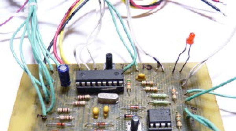
Fig. 3 - Do-it-yourself GSM alarm board - with the installation of parts, front and back sides.

Rice. 4 - Reverse side of the GSM signaling board
Ready-made power supply for alarm:

Rice. 5 - Finished power supply board from the side of the parts

Rice. 6 - Power supply board on the reverse side
I did not become very sophisticated and used the case from the computer's power supply. A case with a built-in transformer can be seen in the figures below:


Not shown here, but a terminal strip was screwed to the left of the power socket with bolts and nuts.


Rice. 7 - device case.
To close the hole from the cooler, I cut out a shaped piece from the chipboard and mounted a clamping ring from the transistor on it - a “reader” for the electronic key. He brought out a couple of LEDs for visual control of the device.


Rice. 8 - Covering the hole from the fan part of the device case.
I glued the cut piece of chipboard with hot glue. On the back panel of the iron case, I brought out the terminal block, connected the outputs of the sensors and the siren to it. Power is supplied to the transformer via a standard cable from the power supply.
Siemens A60 phone connected via a standard connector

Fig. 9 - Plug for mobile
Plug pinout Coincides with any x55/x60/x65. There are two exceptions so far - ST55 / ST60.
1-+U
2-Gnd
3-Tx
4-Rx
5 - CTS
6-RTS
7-DCD
8 - left sound
9 - general sound
10 - right sound
11 - microphone ground
12 - microphone
In accordance with the pinout, it is necessary to solder the wires to the board and power.

Rice. 10 - Connection of two boards (Power supply and GSM alarm)
Then everything was set up and placed in the case. The device was installed to protect a country house. In order to exclude the possibility of an intruder turning off the alarm, I used an old uninterruptible power supply. This made it possible to solve the problem of the operation of the device in the absence of mains power. I used reed switches and a glass break sensor as sensors.
Rice. 11 - RS-232 to TTL level converter (transistor-transistor logic)
The finished device looks like this:
Rice. 12 - Level converter RS-232 - TTL on transistors
Actually the conclusions from the box - common , RX , TX , and a single (milky) wire from the box — «+».
Very important!! - After assembling the device, configure it using the program!
Now a few words about setting up the device.
To set the controller parameters from a PC, the author wrote a simple program. When working in the programming mode, the configuration is written to the memory of the microcontroller. You can also use a configuration file to create a binary image of the EEPROM, which is then written to the chip using a programmer.
To write the parameters, an RS-232 - TTL level converter to a transistor is used. We connect the converter to the COM port of the computer, the RX and TX pins to the board, respectively (RX- 7 leg of the microcontroller, TX - 8 leg of the microcontroller), connect the common wire of the converter to the common track of the board. We apply +5V through the resistors to the converter, as shown in fig. 11, from the power supply.
To write parameters to the microcontroller, before applying power to the entire security device, additionally press the button near the microcontroller, it is responsible for starting the recording. Keep pressed during the entire process of writing parameters through the program. The recording process is fast enough, the finger will not get tired 😉
We connect the power supply of the secret police. Opens the program, select the port, click - "WRITE" - done.
You should prescribe the parameters in the corresponding windows of the program before you decide to program them, because it will be difficult to keep the programming button pressed with one finger, and dial phones with the other, change the working hours, etc.
If someone does not know "Parameters" - these are the phone numbers to which the alarm will ring, also the siren's operating time and the duration of the dial-up, etc. Everything is signed and intuitive in the program.


Rice. 13 - Program interface for flashing the configuration to the controller.
Implementation options:
Enclosure option for signaling. Used case for machine guns. Very comfortable and practical design. Everything you need is inside.

There are enough mounting holes on the back to mount the alarm on any surface.

Inside the shield, you can see that everything fits very well. As for the power supply board, there is none. Everything is powered by a 5 volt power supply from the charger.

Well, actually general form signaling - front side.
Download printed circuit board:
PCB in.lay and description for GSM alarm with key reader-
These Digital Watch protozoa. They were assembled in a few hours. The basis of the PIC16F628A microcontroller, in addition to it, the clock contains several simple and cheap elements, information is displayed on a 4-digit (hour) LED indicator. The circuit is powered from the mains, and also has a backup power supply. This construction can be recommended to beginners, I specially provided the source program with detailed comments to make it easier to understand what and how it works here.
The scheme is very simple, simple and the algorithm of their work (see comments in the source). Buttons kn1 and kn2 are used to correct the time - hours and minutes, respectively. The clock has a 24 hour display format. In the 1st digit of the clock, the blanking of an insignificant zero is done. The accuracy of the clock depends entirely on the frequency of the quartz resonator. But even without special selections of quartz and capacitors in the clock generator, the clock is very accurate.
The clock is assembled on 2 printed circuit boards, docked one to one at an angle of 90 degrees. The whole indicator is placed on one board, and everything else on the other. The backup battery is broken from a Chinese lighter with an LED flashlight. We remove the LED, and install the battery holder on the board. The photo shows that the trimmed resistor leads are connected to the batteries - they then hold the whole structure. Of course, the capacity of such batteries is small, but when the watch is powered by the mains, no current is consumed from the batteries. They feed the circuit only when there is no mains power. In this case, only the microcontroller is powered, the indicator is not powered by batteries, so it goes out, and the clock continues to run. The control buttons are moved from the board to any convenient place in the case. The design of the buttons can be any. For mains power, a Chinese PSU adapter was used, to which a board with a 7805 microcircuit (5-volt stabilizer) was added. Just do any power supply, with an output voltage of 5V and a current of 150mA.
The program is written in such a way that it can be used for the initial study of the PIC microcontroller, the action of almost every command is commented. You can easily add it if you want. additional functions such as calendar, timer, stopwatch, etc.


|
This version of the clock is made in such a way as to simplify the circuit as much as possible, reduce power consumption, and ultimately get a device that fits easily in your pocket. By choosing miniature batteries to power the circuit, SMD mounting and a miniature speaker (for example, from a non-working mobile phone), you can get a design that is slightly larger than a matchbox.
The use of a super-bright indicator allows you to reduce the current consumed by the circuit. Reducing the current consumption is also achieved in the "LoFF" mode - the indicator is off, while only the blinking dot of the least significant bit of the clock is on.
Indication
Adjustable brightness of the indicators allows you to choose the most comfortable display of readings (and again reduce power consumption).
The watch has 9 display modes. The transition through the modes is carried out using the "plus" and "minus" buttons. Before displaying the indications themselves, a short hint of the mode name is displayed on the indicators. The duration of the hint output is one second. The use of short-term hints made it possible to achieve good ergonomics of the watch. When switching between display modes (which turned out to be quite a lot, for such a simple device, like a regular watch) there is no confusion, and it is always clear which readings are displayed on the indicator.

Correction of the readings displayed on the indicator is activated by pressing the "Correction" button. In this case, a short prompt is displayed for 1/4 second, after which the corrected value starts flashing at a frequency of 2 Hz. The readings are adjusted using the plus and minus buttons. When the button is pressed for a long time, the auto-repeat mode is activated, with a given frequency. Button press auto-repeat frequencies are: for hours, months and day of the week - 4 Hz; for minutes, year and indicator brightness - 10 Hz; for the corrective value - 100 Hz.
All corrected values, except for hours, minutes and seconds, are written to EEPROM and restored after turning off - turning on the power. Seconds are reset to zero when corrected. From all modes, except hours-minutes, minutes-seconds and LoFF automatic return is organized. If none of the buttons is pressed within 10 seconds, the watch switches to the hours-minutes display mode.
By pressing the button "On / Off bud." turns on/off the alarm. The activation of the alarm is confirmed by a short two-tone sound. When the alarm clock is on, the dot in the low-order digit of the indicator lights up.
In the "Corr" mode, a correction constant is displayed on the indicator, the initial value of which is 5000 microseconds per second. When the clock lags, we increase the constant by the amount of lag, calculated in microseconds per second. If the clock is in a hurry, then we reduce the constant according to the same principle.
Clock with small 4's digital indicator. The dot between hours and minutes flashes at a frequency of 0.5 seconds. It can be built into any object: a desk calendar, a radio, a car. Estimated error - 0.00002%. In practice, for six months there has never been a need for correction.
Power supply 4.5 - 5 volts, current up to 70mA. The voltage stabilizer is located in the plug - adapter. It is assembled on a 3 watt transformer and a high-frequency converter - stabilizer according to the standard scheme. For a car, of course, a transformer is not needed. The microcircuit without a radiator, practically does not heat up. Connector for power supply 3.5mm. Quartz 4 MHz. Transistors n-p-n any low-power.
Any buttons . The length of the button pusher is selected based on the requirements of the design. You can solder the buttons on the side of the conductors. Each time the button is pressed, one is added. When held, the score accelerates to a reasonable speed.
MLT resistors - 0.25. R7 - R14 300 - 360 ohms. R3 - R6 1-3 kOhm.
Batteries: 4 pieces from GP-170 or similar. When the mains voltage is turned off, they feed only the microcontroller. 8 days stand exactly, checked.
Diodes with the lowest forward voltage drop.
The boards are made of one-sided foil fiberglass.

Before installing the microcontroller into the panel of the manufactured board, turn on the power and measure the voltage on the 14th leg of the panel. Should be 4.5 - 4.8 volts. Pin 5 has 0 volts. If you are not sure about the quality of the manufactured board or the serviceability of the parts, check the device without a microcontroller. This is done very simply:
- Insert a bare wire jumper into the socket, terminals 1 and 14. This means that +4.5 volts from the first leg through the resistor will open the transistor VT 2 and the cathode of the clock unit indicator will be connected to zero.
- Connect any wire with one end to +, and with the other end alternately touch terminals 6,7,8,9,10,11,12,13 of the panel.
- At the same time, observe the igniting segments and their correspondence to the scheme: + on the 6th leg - segment "g" is lit, and so on.
- Move the jumper to terminals 2 and 14 of the panel. Check all segments of the minute units indicator.
- Jumper 18 and 14 - tens of hours are checked, 17 and 14 - tens of minutes.
If something doesn't work, fix it. If everything is correct, program the microcontroller and insert, with the power off, into the socket.
HEX file is attached.
Turn on the power and get your watch ready.

If you buy all the details, including resistors, then, in accordance with my scheme, the device will cost about 400 rubles:
- PIC16F628A - 22.8 UAH
- LM2575T-5.0 – 10 UAH
- FYQ 3641AS21 - 9.3 UAH
- Socket - 3 UAH
- Quartz - 1.5 UAH
Literature:
- Pic microcontrollers. Everything you need to know. Sid Katzen, 2008
- PIC microcontrollers. Architecture and programming. Michael Predko. 2010
- Pic microcontrollers. Application practice. Christian Tavernier, 2004
- Development of embedded systems using PIC microcontrollers. Tim Wilmshurst. 2008
- Data sheet: PIC16F628A, FYQ 3641, LM2575.
- Programming Tutorial PIC controllers for beginners. Evgeny Korabelnikov. 2008
Below you can download firmware and PCB in LAY format
List of radio elements
| Designation | Type | Denomination | Shop | ||
|---|---|---|---|---|---|
| MK PIC 8-bit | PIC16F628A | 1 | Store search | ||
| VR2 | DC/DC switching converter | LM2575 | 1 | 5V | Store search |
| VT1-VT4 | bipolar transistor | KT315A | 4 | Store search | |
| VD1, VD3, VD4 | Diode | D310 | 3 | Store search | |
| VD2 | Schottky diode | 1N5819 | 1 | Store search | |
| VD5 | Diode bridge | DB157 | 1 | Store search | |
| C1, C2 | Capacitor | 20 pF | 2 | Store search | |
| C3 | Capacitor | 0.1uF | 1 | Store search | |
| C4 | 330uF 16V | 1 | Store search | ||
| C5 | electrolytic capacitor | 100uF 35V | 1 | Store search | |
| R1, R2 | Resistor | 10 kOhm | 2 | Store search | |
| R3-R6 | Resistor | 1.5 kOhm | 4 | Store search | |
| R7-R9, R11-R14 | Resistor | 300 ohm | 7 | Store search | |
| R10 | Resistor | 360 ohm | 1 |