Principles of building a local area network. Design and calculation of local area networks Diagram of a local area network in a building
Read also
In itself, the concept of a local network means the association of several computers or computer devices in single system for the exchange of information between them, as well as sharing their computing resources and peripheral equipment. Thus, local networks allow:
Exchange data (movies, music, programs, games, etc.) between network members. At the same time, to watch movies or listen to music, it is absolutely not necessary to record them on your own. HDD. The speeds of modern networks allow you to do this directly from remote computer or multimedia device.
Connect simultaneously several devices to the global Internet through one access channel. This is probably one of the most requested features of local area networks, because today the list of equipment that can use a connection to the World Wide Web is very large. In addition to all kinds of computer equipment and mobile devices, TVs, DVD / Blu-Ray players, multimedia players and even all kinds of household appliances, from refrigerators to coffee makers, have now become full members of the network.
Share computer peripherals such as printers, MFPs, scanners, and network attached storage (NAS).
Share the computing power of computers of network participants. When working with programs that require complex calculations, such as 3D visualization, to increase performance and speed up data processing, you can use the free resources of other computers on the network. Thus, having several weak machines connected to a local network, you can use their total performance to perform resource-intensive tasks.
As you can see, creating a local network, even within the same apartment, can bring a lot of benefits. Moreover, the presence of several devices at once at home that require an Internet connection is not uncommon for a long time, and combining them into a common network is an urgent task for most users.
Basic principles of building a local network
Most often, local networks use two main types of data transfer between computers - by wire, such networks are called cable networks and use Ethernet technology, as well as using a radio signal over wireless networks built on the basis of the IEEE 802.11 standard, which is better known to users under the name Wi -Fi.
To date, wired networks still provide the highest throughput, allowing users to exchange information at speeds up to 100 Mbps (12 Mb / s) or up to 1 Gb / s (128 Mb / s) depending on the equipment used (Fast Ethernet or gigabit ethernet). And although modern wireless technologies, purely theoretically, can also provide data transfer up to 1.3 Gb / s ( wifi standard 802.11ac), in practice this figure looks much more modest and in most cases does not exceed 150 - 300 Mbps. The reason for this is the high cost of high-speed Wi-Fi equipment and the low level of its use in current mobile devices.
As a rule, all modern networks are arranged according to the same principle: user computers (workstations) equipped with network adapters are interconnected through special switching devices, which can be: routers (routers), switches (hubs or switches), access points or modems. We will talk in more detail about their differences and purposes below, but for now just know that without these electronic boxes, it will not work to combine several computers at once into one system. The maximum that can be achieved is to create a mini-network of two PCs by connecting them to each other.
We must not forget that the local network is a "product" with individual solutions for each specific case, which does not tolerate an ill-conceived approach. That is why, like any quality product, a local network must be built by professionals. Let's take a look at what we need to know in order to conduct a quality installation.
At the very beginning, you need to determine the basic requirements for your future network and its scale. After all, the number of devices, their physical placement and possible ways connection, the choice of the necessary equipment will directly depend.  Most often, a home local area network is combined and it can include several types of switching devices at once. For example, desktop computers can be connected to the network using wires, and various mobile devices(laptops, tablets, smartphones) - via Wi-Fi.
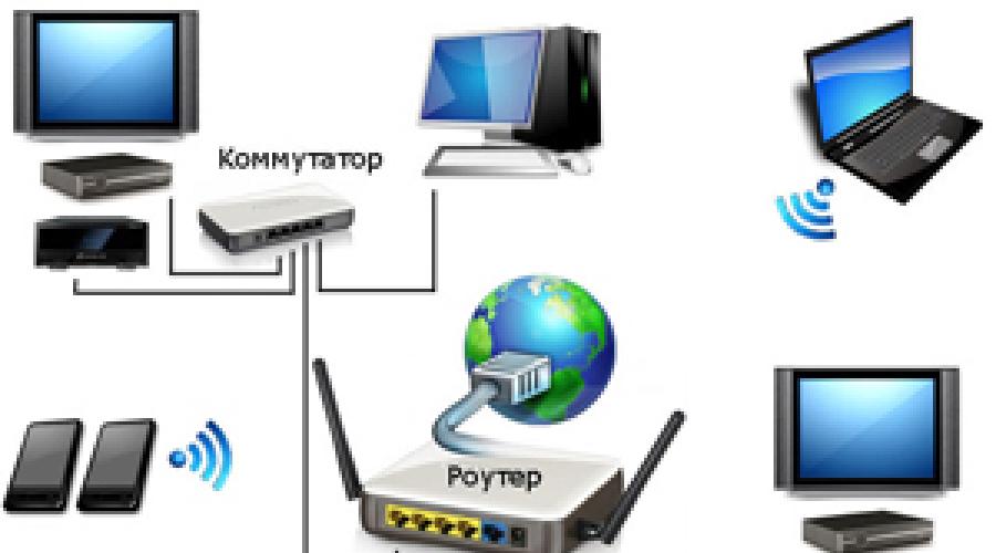
For example, consider a diagram of one of the possible options for a home local network. It will involve electronic devices designed for different purposes and tasks, as well as using a different type of connection.
As can be seen from the figure, several desktop computers, laptops, smartphones, set-top boxes (IPTV), tablets and media players and other devices can be combined into a single network at once. Now let's figure out what kind of equipment you need to build your own network.
LAN card

A network card is a device that allows computers to communicate with each other and exchange data on a network. All network adapters by type can be divided into two large groups - wired and wireless.
Wired network cards allow you to connect electronic devices to a network using Ethernet technology using a cable, and wireless network adapters use Wi-Fi radio technology.
As a rule, all modern desktop computers are already equipped with built-in motherboard Ethernet network cards, and all mobile devices (smartphones, tablets) - network Wi-Fi adapters. At the same time, laptops and ultrabooks are mostly equipped with both network interfaces at once.
Despite the fact that in the vast majority of cases, computer devices have built-in network interfaces, sometimes it becomes necessary to purchase additional boards, for example,  to equip system block wireless module WiFi connections.
According to their constructive implementation, individual network cards are divided into two groups - internal and external. Internal cards are designed to be installed in desktop computers using interfaces and their corresponding PCI and PCIe slots. External boards are connected via USB connectors or outdated PCMCIA (laptops only).
Router (Router)

The main and most important component of a home local network is a router or router - a special box that allows you to combine several electronic devices into a single network and connect them to the Internet through a single channel provided to you by your ISP.
A router is a multifunctional device or even a minicomputer with its own embedded operating system that has at least two network interfaces. The first of them - LAN (Local Area Network) or LAN (Local Area Network) is used to create an internal (home) network, which consists of your computer devices. The second - WAN (Wide Area Network) or WAN (Global Computing Network) is used to connect a local area network (LAN) to other networks and the World Wide Web - the Internet.
The main purpose of devices of this type is to determine the paths (routing) of data packets that the user sends to other, larger networks or requests from them. It is with the help of routers that huge networks are divided into many logical segments (subnets), one of which is the home LAN. Thus, at home, the main function of the router can be called the organization of the transfer of information from the local network to the global network, and vice versa.
Another important task of a router is to restrict access to your home network from the World Wide Web. Surely you are unlikely to be satisfied if anyone can connect to your computers and take or delete from them whatever they want.
To prevent this from happening, the data flow intended for devices belonging to a specific subnet must not go beyond its limits. Therefore, the router from the total internal traffic generated by the members of the local network selects and sends to the global network only that information that is intended for other external subnets. This ensures the security of internal data and saves overall network bandwidth.
The main mechanism that allows the router to restrict or prevent access from the public network (outside) to devices on your local network is called NAT (Network Address Translation). It also provides all users of the home network with access to the Internet by converting several internal addresses of devices into one public external address provided by your Internet service provider. All this makes it possible for computers on the home network to easily exchange information with each other and receive it from other networks. At the same time, the data stored in them remains inaccessible to external users, although at any time access to them can be provided at your request.
In general, routers can be divided into two large groups - wired and wireless. Already by the names it is clear that all devices are connected to the first ones only with the help of cables, and to the second ones, both with the help of wires and without them using Wi-Fi technology. Therefore, at home, it is wireless routers that are most often used, which allow providing the Internet and networking computer equipment using various communication technologies.

To connect computer devices using cables, the router has special sockets called ports. In most cases, the router has four LAN ports for connecting your devices and one WAN port for connecting an ISP cable.
In many cases, the router may be the only component needed to build your own local network, as there will simply be no need for the rest. As we have already said, even the simplest router allows you to connect up to four computer devices using wires. Well, the number of equipment that receives simultaneous access to the network using Wi-Fi technology can even be in the tens, or even hundreds.
If, nevertheless, at some point the number of LAN ports of the router ceases to be enough, then to expand the cable network, one or more switches can be connected to the router (we will discuss them below), which act as splitters.
Modem
In modern computer networks, a modem is a device that provides access to the Internet or access to other networks through conventional wired networks. telephone lines(xDSL class) or using mobile wireless technology (3G class).
 Conventionally, modems can be divided into two groups. The first includes those that connect to the computer via the USB interface and provide access to the network only one specific PC, to which the modem is directly connected. In the second group, LAN and / or Wi-Fi interfaces already familiar to us are used to connect to a computer. Their presence indicates that the modem has a built-in router. Such devices are often called combined, and they should be used to build a local network.

When choosing DSL equipment, users may encounter certain difficulties caused by confusion in its names. The fact is that often in the assortment of computer stores, two very similar classes of devices coexist at once: modems with built-in routers and routers with built-in modems. What is their difference?
There are practically no key differences between these two groups of devices. Manufacturers themselves position a router with a built-in modem as a more advanced option, endowed with big amount additional features and improved performance. But if you are only interested in basic features, such as, for example, connecting all computers on your home network to the Internet, then there is little difference between modem routers and routers where, as an external network interface using a DSL modem, no.
So, to summarize, a modern modem with which you can build a local network is, in fact, a router with an xDSL or 3G modem acting as an external network interface.
Switch
A switch or switch is used to connect various nodes of a computer network and exchange data between them via cables.
The role of these nodes can be either separate devices, such as a desktop PC, or entire groups of devices already combined into an independent network segment. Unlike a router, the switch has only one network interface - LAN and is used at home as an auxiliary device, mainly for scaling local networks.

To connect computers using wires, like routers, switches also have special socket-ports. In models focused on home use, usually their number is five or eight. If at some point the number of switch ports is no longer enough to connect all devices, you can connect another switch to it. Thus, you can expand your home network as much as you like.
Switches are divided into two groups: managed and unmanaged. The first thing that follows from the name can be controlled from the network using a special software. With advanced functionality, they are expensive and not used in the home. Unmanaged switches distribute traffic and regulate the speed of data exchange between all network clients in automatic mode. It is these devices that are ideal solutions for building small and medium-sized local networks, where the number of participants in the exchange of information is small.
Depending on the model, the switches can provide a maximum data transfer rate of either 100 Mbps (Fast Ethernet) or 1000 Mbps (Gigabit Ethernet). Gigabit switches are best used for building home networks where you plan to transfer files frequently. big size between local devices.
Wireless access point
To provide wireless access to the Internet or local network resources, in addition to the wireless router, you can use another device called a wireless access point.
Unlike a router, this station does not have an external WAN network interface and is equipped in most cases with only one LAN port for connecting to a router or switch. Thus, you will need an access point if your local network uses a regular router or modem without Wi-Fi support.

The use of additional access points in a network with a wireless router can be justified in cases where a large Wi-Fi coverage area is required. For example, the signal strength of a wireless router alone may not be enough to cover the entire area in a large office or a multi-storey country house.
Access points can also be used to organize wireless bridges that allow you to connect individual devices, network segments or entire networks using a radio signal in places where cabling is undesirable or difficult.
Network cable, connectors, sockets
Despite the rapid development wireless technologies, until now, many local networks are built using wires. Such systems have high reliability, excellent throughput and minimize the possibility of unauthorized connections to your network from outside.

To create a wired local area network in home and office environments, Ethernet technology is used, where the signal is transmitted over the so-called "twisted pair" (TP-Twisted Pair) - a cable consisting of four copper twisted pairs of wires with each other (to reduce interference).
When building computer networks, mostly unshielded CAT5 cable is used, and more often its improved version CAT5e. Cables of this category allow you to transmit a signal at a speed of 100 Mbps when using only two pairs (half) of wires, and 1000 Mbps when using all four pairs.

To connect to devices (routers, switches, network cards, and so on), the ends of the twisted pair use 8-pin modular connectors, commonly referred to as RJ-45 (although their correct name is 8P8C).
Depending on your desire, you can either buy ready-made (with crimped connectors) network cables of a certain length, called “patch cords” in any computer store, or purchase twisted pair and connectors separately, and then make cables of the required size yourself in the right amount.
Using cables to connect computers to a network, of course, you can connect them directly from switches or routers to connectors on network cards PC, but there is another option - the use of network outlets.
In this case, one end of the cable is connected to the switch port, and the other to the internal contacts of the socket, in the external connector of which you can later connect computer or network devices.

Power outlets can be built into the wall or mounted outside. The use of sockets instead of protruding cable ends will give a more aesthetic look to your workplace. It is also convenient to use sockets as reference points for various network segments. For example, you can install a switch or router in the hallway of the apartment, and then from it thoroughly lay cables to sockets located in all necessary rooms. Thus, you will get several points located in different parts of the apartment, to which you can connect not only computers, but also any network devices at any time, for example, additional switches to expand your home or office network.
Another little thing that you may need when building a cable network is an extension cable, which can be used to connect two twisted pairs with already crimped RJ-45 connectors.
In addition to their direct purpose, extension cords are convenient to use in cases where the end of the cable ends with not one connector, but two. This option is possible when building networks with a bandwidth of 100 Mbps, where only two pairs of wires are sufficient to transmit a signal.
 You can also use a network splitter to connect two computers to one cable at once without using a switch. But again, it is worth remembering that in this case maximum speed data exchange will be limited to 100 Mbps.
Read more about twisted pair crimping, connecting sockets and the characteristics of network cables in a special material.
Network topology
Now that we've seen the basic components of a LAN, it's time to talk about topology. If to speak plain language, then a network topology is a diagram that describes the locations and how network devices are connected.
There are three main types of network topology: Bus, Ring, and Star. With a bus topology, all computers on the network are connected to one common cable. To combine PCs into a single network using the "Ring" topology, they are serial connection with each other, with the last computer connected to the first. With a star topology, each device is connected to the network through a special hub using a separate cable.
Probably, the attentive reader has already guessed that to build a home or small office network, the Star topology is mainly used, where routers and switches are used as hub devices.
Creating a network using the Zvezda topology does not require deep technical knowledge and large financial investments. For example, using a switch that costs 250 rubles, you can network 5 computers in a few minutes, and using a router for a couple of thousand rubles, you can even build a home network, providing several dozen devices with access to the Internet and local resources.
Another undoubted advantage of this topology is good scalability and ease of upgrade. Thus, network branching and scaling is achieved by simply adding additional hubs with the necessary functionality. Also, at any time, you can change the physical location of network devices or swap them in order to achieve more practical use of equipment and reduce the number and length of connecting wires.
Despite the fact that the Zvezda topology allows you to quickly change the network structure, the location of the router, switches and other necessary elements must be thought out in advance, in accordance with the layout of the room, the number of connected devices and how they are connected to the network. This will minimize the risks associated with the purchase of unsuitable or redundant equipment and optimize the amount of your financial costs.
Conclusion
In this article, we reviewed general principles building local networks, the main equipment that is used and its purpose. Now you know that the main element of almost any home network is a router, which allows you to network many devices using both wired (Ethernet) and wireless (Wi-Fi) technologies, while providing all of them with an Internet connection through one single channel.
Switches are used as ancillary equipment to expand the points of connection to the local network using cables, which are essentially splitters. For the organization wireless connections are access points that allow using Wi-Fi technology not only to connect all kinds of devices wirelessly to the network, but also in the "bridge" mode to connect entire segments of the local network.
In order to understand exactly how much and what kind of equipment you will need to purchase to create a future home network, be sure to first draw up its topology. Draw a diagram of the location of all devices participating in the network that will need to cable connection. Depending on this, select the optimal location for the router and, if necessary, additional switches. There are no uniform rules here, since the physical location of the router and switches depends on many factors: the number and type of devices, as well as the tasks that will be assigned to them; the layout and size of the room; requirements for the aesthetics of the type of switching nodes; possibilities for laying cables and others.
So, as soon as you have a detailed plan for your future network, you can begin to move on to the selection and purchase of the necessary equipment, its installation and configuration. But we will talk about these topics in our next materials.
Due to the large area of the territory, a large number of buildings, workshops, departments and users (about 1500 users), in order to improve the performance and fault tolerance of the network, it is necessary to divide it into logically independent objects that will be interconnected by network node devices. At the same time, dividing a large network into smaller ones will make it easier to administer. Thus, the enterprise LAN topology will be implemented as a hierarchical star. A family of high-speed versions of Ethernet will be used as the link layer technology.
To ensure the division of responsibility between the switches, a typical architecture will be used, consisting of: network core level switches, distribution level switches and access level switches. Switches installed at the network core level require high performance and fault tolerance. Since the performance of the entire network will depend on them. Distribution switches will be located throughout the enterprise, closer to access switch groups, to which end users of LAN resources are already connected. Server cabinet switches are connected directly to the network core switch, which serve the so-called SAN (Storage area network), local networks inside server cabinets.
The enterprise is divided into 5 zones, each of which will be serviced from its distribution level switch. The zones are selected depending on the location and the number of users. The enterprise LAN scheme is shown in Figure 2.
Logically, such a large network should be divided into several smaller networks. With this approach, network performance will increase, since broadcast and other “weed traffic” will not be distributed throughout the network, taking up network bandwidth. In the event of a network outage, such as a broadcast storm, only a small logical piece of the network will go down, and the problem can be identified and fixed much faster. That is, in this case, the convenience of network administration is provided. When carrying out any work on restructuring the network, it will be possible to do this in parts, which simplifies the work network administrators and allows a small number of users to be taken out of service for the duration of the work.
Figure 2 - Enterprise LAN Topology
To divide the network into will be used virtual technology local area network (VLAN). Each division, and sometimes a group of smaller divisions, will have its own virtual network. Several vlans will also be created to connect the network core switches and the distribution layer. Each such network will use unique network addresses. Virtual networks will use core and distribution switch ports to place departments in their unique vlans. This will be done during the configuration of active network devices.
As can be seen from the diagram, several logical channels will be used to link the core and distribution switches. The network core topology "star + ring" will be implemented. Channels diverge from the core switch in a star to distribution switches, they are highlighted in blue in the diagram. Thus, a "star" is obtained. These channels will be allocated to a separate vlan, which will be used only for communication between backbone switches.
Channels that will link the backbone switches into a “ring” are highlighted in yellow. Previously, it was not allowed to create loops in Ethernet networks. But the requirements for network reliability have led to the fact that technologies have been developed that can support redundant links in the network to redundant channels. Ethernet Ring Protection Switching (ERPS) is one of the technologies that allow you to organize fault-tolerant network topologies. It was chosen over Rapid Spanning Tree Protocol (RSTP) for fast time restoration of network operability in case of failure of one of the channels. For the RSTP protocol, the convergence time is less than 10 seconds, while for ERPS it is less than 50 milliseconds. It will also be a separate vlan, used only by backbone switches.
Dynamic routing will be used to combine all virtual networks and find routes between them. Namely, the Open Shortest Path First version 2 (OSPFv2) protocol. Each of the backbone switches will be able to work at the 3rd level of the OSI model, that is, it will be an L3 level switch. In the OSPF protocol domain, one backbone zone will be allocated - the backbone. It will contain only routers (built into L3 switches) that will exchange information about the virtual networks connected to them. This protocol requires a Designated root (DR) for the OSPF domain and requires a Backup designated root (BDR). The core level switch will be used as the DR, and one of the distribution level switches will be used as the BDR.
Each user access level switch will be used in its specific vlan allocated for it on the distribution level switch. In some cases, such switches can be used to connect switches to a smaller number of ports, but this does not matter for the logic of the network.
Thus, a productive, fault-tolerant and easily scalable local area network architecture is organized.
Modern computer technologies cannot be imagined without combining all kinds of devices in the form of stationary terminals, laptops or even mobile devices into a single network. Such an organization allows not only to quickly exchange data between different devices, but also to use the computing capabilities of all pieces of equipment connected to the same network, not to mention the possibility of access to peripheral components such as printers, scanners, etc. But what are the principles by which such Union? To understand them, it is necessary to consider the local network, often called the topology, which will be discussed further. To date, there are several main classifications and types of combining any devices that support network technologies into one network. Of course, we are talking about those devices on which special wired or wireless network adapters and modules are installed.
Schemes of local computer networks: the main classification
First of all, in considering any type of organization of computer networks, it is necessary to start solely from the method of combining computers into a single whole. There are two main directions used in creating a local network diagram. The network connection can be either wired or wireless.
In the first case, special coaxial cables or twisted pairs are used. This technology is called Ethernet connection. However, if coaxial cables are used in the local computer network, their maximum length is about 185-500 m at a data transfer rate of not more than 10 Mbps. If twisted pairs of classes 7, 6 and 5e are used, their length can be 30-100 m, and the throughput ranges from 10-1024 Mbps.

The wireless scheme for connecting computers in a local network is based on the transmission of information via a radio signal, which is distributed between all connected devices, distributing devices, which can be routers (routers and modems), access points (regular computers, laptops, smartphones, tablets), switching devices (switches, hubs), signal repeaters (repeaters), etc. With this organization, fiber optic cables are used that are connected directly to the main signal-distributing equipment. In turn, the distance over which information can be transmitted increases to about 2 km, and in the radio frequency range, frequencies of 2.4 and 5.1 MHz are mainly used (IEEE 802.11 technology, better known as Wi-Fi).
Wired networks are considered to be more secure from external influences, since it is not always possible to directly access all terminals. Wireless structures lose quite a lot in this regard, because if desired, a competent attacker can easily calculate the network password, gain access to the same router, and through it get to any device, in this moment using a Wi-Fi signal. And very often in the same state structures or in the defense enterprises of many countries, the use of wireless equipment is strictly prohibited.
Classification of networks according to the type of connection between devices
Separately, it is possible to single out a fully connected topology of schemes for connecting computers in a local network. Such a connection organization implies only that absolutely all terminals included in the network have a connection with each other. And as it is already clear, such a structure is practically not protected in terms of external intrusion or when intruders penetrate the network through special virus worms or spyware applets that could initially be recorded on removable media, which the same inexperienced employees of enterprises unknowingly could connect to your computers.
That is why other connection schemes in the local network are most often used. One of these can be called a cellular structure, from which certain initial connections have been removed.
General scheme for connecting computers in a local network: the concept of the main types of topology
Now let's take a quick look at wired networks. They can use several of the most common types of local area networking schemes. The most basic types are star, bus, and ring structures. True, it is the first type and its derivatives that have received the greatest use, but mixed types of networks can often be found, where combinations of all three main structures are used.
Star topology: pros and cons
The “star” local network scheme is considered the most common and widely used in practice when it comes to using the main types of connection, so to speak, in its purest form.

The essence of such a combination of computers into a single whole is that they are all connected directly to the central terminal (server) and do not have any connections with each other. Absolutely all transmitted and received information passes directly through the central node. And it is this configuration that is considered the most secure. Why? Yes, only because the introduction of the same viruses into the network environment can be done either from the central terminal, or get through it from another computer device. However, it looks very doubtful that in such a scheme of the local network of an enterprise or government institution a high level of protection of the central server will not be provided. And injecting spyware from a separate terminal will only work if you have physical access to it. In addition, and from the side of the central node for each network computer quite serious restrictions can be imposed, which can be especially often observed when using network operating systems, when computers do not even have hard disks, and all the main components of the applied OS are loaded directly from the main terminal.
But even here there are drawbacks. First of all, this is due to the increased financial costs for laying cables if the main server is not located in the center of the topological structure. In addition, the speed of information processing directly depends on the computing capabilities of the central node, and if it fails, respectively, on all computers included in the network structure, communications are broken.
Bus scheme
The connection scheme in the local network according to the “bus” type is also one of the most common, and its organization is based on the use of a single cable, through the branches of which all terminals, including the central server, are connected to the network.

The main disadvantage of such a structure can be called the high cost of laying cables, especially for those cases when the terminals are at a sufficiently large distance from each other. But if one or more computers fail, communications between all other components in the network environment are not broken. In addition, when using such a scheme, the local network passing through the main channel is very often duplicated in different areas, which makes it possible to avoid its damage or the impossibility of its delivery to its destination. But security in such a structure, alas, suffers quite a lot, since malicious virus codes can penetrate all other machines through the central cable.
Ring structure
The ring scheme (topology) in a sense can be called obsolete. To date, it is not used in almost any network structure (except perhaps only in mixed types). This is due precisely to the very principles of combining individual terminals into one organizational structure.

Computers are connected to each other in series and with only one cable (roughly speaking, at the input and output). Of course, such a technique reduces material costs, but if at least one network unit fails, the integrity of the entire structure is violated. If I may say so, in a certain area where there is a damaged terminal, the transmission (passage) of data simply stops. Accordingly, when dangerous computer threats penetrate the network, they pass from one terminal to another in the same way. But if there is reliable protection at one of the sites, the virus will be eliminated and will not pass further.
Mixed types of networks
As mentioned above, the main types of local area network schemes in their pure form are practically not found. Mixed types look much more reliable in terms of security, cost, and ease of access, in which elements of the main types of network diagrams may be present.

So, very often you can find networks with a tree structure, which initially can be called a kind of “star”, since all branches come from one point, called the root. But the organization of branches in such a LAN connection scheme can contain both ring and bus structures, dividing into additional branches, often defined as subnets. It is clear that such an organization is quite complex, and when creating it, it is necessary to use additional technical devices such as network switches or splitters. But, as they say, the end justifies the means, because thanks to such a complex structure, important and confidential information can be protected very reliably by isolating it in subnet branches and practically restricting access to it. The same applies to the failure of components. With such a construction of local network schemes, it is not necessary to use only one central node. There can be several of them, and with completely different levels of protection and access, which further increases the degree of overall security.
Logistic topology
When organizing network structures, it is especially important to pay attention to the methods of data transmission used. In computer terminology, such processes are usually called logistic or logical topology. At the same time, the physical methods of information transfer in various structures can differ significantly from the logical ones. It is logistics, in essence, that determines the routes of reception / transmission. Very often it can be observed that when building a network in the form of a "star", information exchange is carried out using a bus topology, when the signal can be received simultaneously by all devices. In ring logical structures, situations can be encountered when signals or data are received only by those terminals for which they are intended, despite even sequential passage through all related links.
The most famous networks
So far, only the construction of local area network schemes based on Ethernet technology has been considered above, which in itself simple expression uses addresses, protocols, and TCP/IP stacks. But after all, in the world you can find a huge number of network structures that have different principles of network organization from the above. The best known of all (except Ethernet using a logical bus topology) are Token Ring and Arcnet.

The Token Ring network structure was once developed by the notorious IBM company and is based on the logical scheme of the local network “token ring”, which determines the access of each terminal to the transmitted information. Physically, a ring structure is also used, but it has its own characteristics. To combine computers into a single whole, it is possible to use either twisted pair or fiber optic cable, but the data transfer rate is only 4-16 Mbps. On the other hand, the "star" type marker system allows to transmit and receive data only to those terminals that have the right to do so (marked with a marker). But the main disadvantage of such an organization is that at a certain moment only one station can have such rights.
No less interesting is the Arcnet LAN scheme, created in 1977 by Datapoint, which many experts call the most inexpensive, simple and very flexible structure.

To transfer information and connect computers, coaxial or fiber optic cables can be used, but the possibility of using a twisted pair cable is also not excluded. True, in terms of the speed of reception / transmission, this structure cannot be called particularly productive, since at the maximum packet exchange can be carried out at a connection speed of no more than 2.5 Mbps. As a physical connection, the "star" scheme is used, and in the logical - "marker bus". With the rights to receive / transmit, the situation is exactly the same as in the case of Token Ring, except that the information transmitted from one machine is available to absolutely all terminals included in the network environment, and not to any one machine.
Brief information about setting up a wired and wireless connection
Now let's briefly dwell on some important points in the creation and application of any of the described local network schemes. Third-party programs when using any of the known operating systems are not needed to perform such actions, since the main tools are provided in their standard sets from the very beginning. However, in any case, it is necessary to take into account some important nuances regarding the configuration of IP addresses, which are used to identify computers in network structures. There are only two varieties - static and dynamic addresses. The first, as the name already implies, are constant, and the second can change with each new connection, but their values are exclusively in the same range set by the communication service provider (provider).
In wired corporate networks, to ensure high speed data exchange between network terminals, static addresses are most often used, assigned to each machine on the network, and when organizing a network with wireless connection usually dynamic addresses are involved.
To set the specified parameters of a static address in Windows systems, the parameters of the IPv4 protocol are used (in the post-Soviet space, the sixth version has not yet become particularly widespread).

It is enough to write an IP address for each machine in the protocol properties, and the subnet mask and default gateway parameters are common (unless a tree structure with multiple subnets is used), which looks very convenient from the point of view of quick setup connections. Despite this, dynamic addresses can also be used.

They are assigned automatically, for which there is a special item in the TCP / IP protocol settings, at each specific point in time they are assigned to network machines directly from the central server. The range of allocated addresses is provided by the provider. But this does not mean at all that the addresses are repeated. As you know, there cannot be two identical external IPs in the world, and in this case we are talking either about the fact that they change only within the network or are transferred from one machine to another when some external address is free.
In the case of wireless networks, when routers or access points are used for the initial connection, distributing (broadcasting or amplifying) the signal, the setup looks even easier. The main condition for this type of connection is to set the automatic receipt of an internal IP address. Without this, the connection will not work. The only changeable parameter is the DNS server addresses. Despite the initial setting of their automatic receipt, it is often (especially when the connection speed is reduced) that it is recommended to set such parameters manually, using, for example, free combinations distributed by Google, Yandex, etc.
Finally, even if there is only a certain set of external addresses by which any computer or mobile device is identified on the Internet, they can also be changed. For this, there are many special programs. The local network scheme can have any of the above variations. And the essence of using such tools, which are most often either VPN clients or remote proxy servers, is to change the external IP, which, if anyone does not know, has a clear geographical reference, to an unoccupied address located in a completely different location (even at the end of the world). You can use such utilities directly in browsers (VPN clients and extensions) or make changes at the level of the entire operating system (for example, using the SafeIP application) when some applications running in the background need to access blocked or inaccessible for a certain region Internet resources.
Epilogue
Summing up all of the above, several main conclusions can be drawn. The first and most important thing is that the basic connection schemes are constantly changing, and they are almost never used in the initial version. The most advanced and most secure are complex tree structures, in which several subordinate (dependent) or independent subnets can additionally be used. Finally, no matter what anyone says, at the present stage of development of computer technology, wired networks, even despite the high financial costs of their creation, are still head and shoulders above the simplest wireless ones in terms of security. But wireless networks have one indisputable advantage - they allow you to combine computers and mobile devices that can be geographically distant from each other over very long distances.
Introduction
The object of undergraduate practice is an educational institution MBOU secondary school d.Novaya Derevnya.
The purpose of undergraduate practice is to create an information system (IS) of the school.
The information system is a local computer network for the school. Its main purpose is to connect school computers to each other in a local network with subsequent access to the Internet.
A local network will be created for the sharing of peripheral equipment and information resources. Internet access is necessary for the school to communicate with other organizations (for example, GorUO), as well as for students and teachers to access information resources the Internet. In addition to solving the basic issues of IS design, electronic checkpoint systems (EPS), a unified information system (UIS) and a video surveillance system (VNS) will be introduced in the building being designed.
The projected local area network (LAN) must meet the latest requirements for networks of educational institutions, provide reliable centralized storage and protection of data, transfer data at high speed and communicate with other educational institutions. In addition, further expansion of the network should not be associated with high costs. With the further acquisition of a PC by the school, the network should allow simple expansion. It is also necessary to make maximum use of available software and hardware.
Purpose: to gain practical skills in network design. Learn how to choose network technologies and components and be able to justify your choice. Design the school information system.
Design a LAN;
Implement systems of BOT, UIS, SVN;
Organize access to the Internet;
Ensure the use of peripheral devices;
Select the required software;
Test IS.
1 Diagram of a local area network
The design will use a star topology. The hierarchical star consists of the main switch to which the workstations are connected. The star topology has a number of advantages:
– inexpensive cable and quick installation;
– easy association of working groups;
– simple network expansion.
The advantage of this topology is also the ability to easily exclude a failed node. The star topology provides cable break protection. If the workstation cable is damaged, this will not lead to failure of the entire network segment. It also makes it easy to diagnose connection problems, as each work station has its own cable segment connected to the switch. For diagnostics, it is enough to find a cable break that leads to a non-working station. The rest of the network continues to function normally.
A client-server architecture was chosen for the school. In doing so, I was guided by the following reasons:
– the number of users exceeds ten;
– requires centralized resource management or backup;
– a specialized server is required;
- you need access to the global network;
– it is required to share resources at the user level;
– Provides centralized management of user accounts, security, and access to simplify network administration.
The client-server architecture is the concept of an information network in which the bulk of its resources are concentrated in servers serving their clients. This architecture defines two types of components: servers and clients.
A server is an object that provides a service to other network objects at their request. Service is the process of serving customers. The server works on the instructions of clients and manages the execution of their tasks. After each job is completed, the server sends the results to the client that submitted the job.
A process that calls a service function with certain operations is called a client. It can be a program or a user.
Clients are workstations that use server resources and provide convenient user interfaces.
Client-server architecture networks have the following advantages:
− provide centralized management of user accounts, security and access, which simplifies network administration;
− allow organizing networks with a large number of workstations;
− provide effective access to network resources;
- provide access to all network resources, based on account user.
Figure 1 shows the projected scheme of the IS of the school.
|
Figure 1 - IS scheme |
2 Modeling a local area network

3 Information system
3.1 Electronic gate system (EP)
A modern school, in addition to organizing the educational process, must ensure the safety of students at school and promptly inform parents about emerging problems. SEP is specially designed for educational institutions, not only prevents the entry of strangers, but also notifies parents using SMS messages about the time the child arrives at school and leaves it. The control of absenteeism and lateness of students contributes to the improvement of attendance and, as a result, the growth of the quality of knowledge. Parents' confidence in the safety of the child at school and the growth of knowledge quality indicators increase the rating of the educational institution. For the implementation of the BOT, a set of electronic checkpoints was purchased. The kit included:
Ip turnstile;
Basic software;
Remote control;
Contactless access cards.
The operating principle of the EPS is presented in Table 10.
Table 10 - Principle of operation
Table 10 continued
|
Pupils, teachers and employees of the educational institution are issued electronic plastic pass cards. |
|
|
Information about students and school staff and the cards issued to them is entered into the system's memory. |
|
|
To pass through the turnstile, you need to bring your pass card to a special board on the turnstile. |
|
|
Information from the card is read automatically, and if the card is registered in the system, the turnstile will open for passage. |
|


Table 10 continued
A structured cabling system is a set of switching elements (cables, connectors, cross panels and cabinets), as well as a technique for sharing them, which allows you to create regular, easily expandable communication structures in computer networks.
A structured cabling system is a kind of "constructor", with the help of which the network designer builds the configuration he needs from standard cables connected by standard connectors and switched on standard cross panels. If necessary, the connection configuration can be easily changed - add a computer, segment, switch, remove unnecessary equipment, and also change the connections between computers and switches.
When building a structured cabling system, it is understood that every workplace in the enterprise must be equipped with sockets for connecting a phone and a computer, even if this is not needed at that moment. That is, a good structured cabling system is built redundant. This can save money in the future, since changes to the connection of new devices can be made by reconnecting already laid cables.
According to the task, the block diagram of the location of buildings, each of which has its own subnet, is shown in Fig. 2.1.
Figure 2.1 - Block diagram of the location of buildings
The block diagram of the subnetworks of each of the buildings is shown in fig. 2.2 - 2.3. Since there are two 5-storey buildings, and they have the same number of switching equipment and PCs, their block diagrams are identical.

Figure 2.2 - Structural diagram of the subnetwork of a 5-storey building

Figure 2.3 - Structural diagram of the subnetwork of a 4-storey building
The block diagram of connecting subnets into one network is shown in fig. 2.4.

Figure 2.4 - General block diagram of the network
In buildings, the technology is FastEthernet, between buildings - FDDI, Internet access from each building via a radio channel.
3 Equipment and cable selection
3.1 Switch selection
A switch is a device designed to connect several nodes of a computer network within one or more network segments. The switch operates at the data link layer of the OSI model. Unlike a hub that distributes traffic from one connected device to all others, a switch only forwards data directly to the recipient. This improves network performance and security by eliminating the need for other segments of the network to process data that was not intended for them.
In this course project, in each room of the buildings there are room switches - workgroup switches, on each floor - a floor switch that combines workgroup switches on its floor, and a root switch located in the server room on the first floor, to which the switches of all floors are connected.
Switching equipment (switches, routers) was selected from the manufacturer Cisco. According to the Dell "Oro Group, Cisco occupies 60% of the global network equipment market, that is, more than all other competitors. This manufacturer has the widest line of all network solutions, a wide range of technologies, protocols, ideologies, both standard and and our own, allowing you to expand the capabilities of the network, the broadest troubleshooting capabilities built into almost all Cisco devices.
Based on the optimal ratio of price, performance and functionality, the following models of switches were selected, belonging to the Cisco 300 series, designed specifically for small businesses. The line includes a range of low cost managed switches that provide a powerful foundation for maintaining a corporate network.
Cisco 300 Series Switch Features
provide the high availability and performance needed for mission-critical business applications while minimizing potential downtime.
allow you to control network traffic using modern features such as quality of service analysis, static routing of the third layer, support for the IPv6 protocol.
have clear tools with a web interface; the possibility of mass deployment; similar functions in all models.
allow you to optimize energy consumption without affecting performance.
3.1.1 Workgroup switches
According to the task for the course work in a 4-storey building in three rooms on each floor there are 35 computers, and in two 5-storey buildings in one room on each floor there are 31 computers, for connecting which the SG300-52 switch is selected, which has 48 ports (Figure 3.1).

Figure 3.1 - Workgroup switch SG300-52
Switch SG300-52 (price: 7522 UAH), manufactured by Cisco, is equipped with 48 10/100/1000 Mbps ports for Ethernet networks with automatic speed negotiation for RJ45 ports, which facilitates installation of the device.
This switch provides good performance and can improve workgroup performance and network and host throughput, ensuring easy and flexible installation and configuration. Due to the compact size of the body, the device is ideal for placement on a limited desktop space; also the device can be mounted in a rack. Dynamic LEDs display the switch's real-time status and allow basic diagnostics of the device's operation.
The main technical characteristics of the SG300-52 switch are presented in Table 3.1.
Table 3.1 - Technical characteristics of the switch SG300-52
|
managed switch |
|
|
Interface |
4 x SFP (mini-GBIC), 48 x Gigabit Ethernet (10/100/1000 Mbps) |
|
SNMP 1, RMON 1, RMON 2, RMON 3, RMON 9, Telnet, SNMP 3, SNMP 2c, HTTP, HTTPS, TFTP, SSH, |
|
|
Routing Protocol |
Static IPv4 routing, 32 routes |
|
MAC address table |
16000 entries |
|
128 MB (RAM), Flash memory - 16 MB |
|
|
Encryption algorithm | |
|
Additional features |
Up to 32 static routes and up to 32 IP interfaces DHCP layer 3 translation User Datagram Protocol (UDP) translation Smartports feature simplifies configuration and security management Built-in configuration utility, web-based access (HTTP/HTTPS) Dual stack IPv6 and IPv4 protocols Upgradable software |
|
Supported standards |
IEEE 802.3 10BASE-T Ethernet, IEEE 802.3u 100BASE-TX Fast Ethernet, IEEE 802.3ab 1000BASE-T Gigabit Ethernet, IEEE 802.3ad LACP, IEEE 802.3z Gigabit Ethernet, IEEE 802.3x Flow Control, IEEE 802.1D (STP, GARP, and GVRP),IEEE 802.1Q/p VLAN, IEEE 802.1w RSTP, IEEE 802.1s Multiple STP, IEEE 802.1X Port Access Authentication, IEEE 802.3af, IEEE |
|
Internal power supply. 120-130VAC, 50/60Hz, 53W. |
|
|
Surrounding conditions. environments |
Operating temperature: 0°C ~40°C |
|
Dimensions (WxDxH) |
440*260*44mm |
For two 5-storey buildings, which have 18 and 25 computers in the remaining rooms on each floor, respectively, 18 computers are selected for connection - a switch for 24 ports - SF300-24P (price: 4042 UAH), and for connection 25 computers - two switches, each for 16 ports - SG300-20 (price: UAH 3023), which are shown in fig. 3.2. The remaining ports are reserved.


Figure 3.2 - Workgroup switch SF300-24P (a) and SG300-20 (b)
The SF300-24P is a 24-port managed network switch. These switches provide all the features you need to run mission-critical business applications, protect sensitive information, and optimize bandwidth for more efficient network transmission. Plug-and-play and auto-negotiation support allow the switch to automatically detect the type of connected device (such as an Ethernet network adapter) and select the most appropriate speed. LED indicators are used for cable connection control and standard diagnostics. The switch can be desktop-mounted or rack-mounted.
Designed for small workgroups, the SG300-20 is equipped with 18 10/100/1000BASE-TX Ethernet ports and 2 mini-GBICs. The functionality of these switches is similar to the functionality of the SF300-24P switch, since they both belong to the same Cisco 300 series.
The main technical characteristics of the SF300-24P switch are presented in table 3.2, and the SG300-20 switch - table. 3.3.
Table 3.2 - Technical characteristics of the SF300-24P switch
|
managed switch |
|
|
Interfaces |
24 Ethernet 10Base-T/100Base-TX ports - RJ-45 connector, PoE support; console control port - 9 pin D-Sub (DB-9); 4 Ethernet ports 10Base-T/100Base-TX/1000Base-T - RJ-45 connector, 2 port for SFP (mini-GBIC) modules. |
|
Protocol remote administration | |
|
Routing Protocol |
Static IPv4 routing |
|
MAC address table |
16000 entries |
|
128 MB (RAM), Flash memory - 16 MB |
|
|
Encryption algorithm | |
|
Control |
SNMP version 1, 2c, and 3 Built-in RMON software agent for traffic management, monitoring, and analysis Dual-stack IPv6 and IPv4 protocols Software updates DHCP port mirroring (options 66, 67, 82, 129, and 150) Smartports feature simplifies configuration and security management Cloud-based services Other management functions: Traceroute; management through a single IP address; HTTP/HTTPS; SSH RADIUS; DHCP client; BOOTP; SNTP xmodem update; cable diagnostics; ping; system log; Telnet client (SSH support) |
|
Supported standards |
IEEE 802.3 10BASE-T Ethernet IEEE 802.3u 100BASE-TX Fast Ethernet IEEE 802.3ab 1000BASE-T Gigabit Ethernet IEEE 802.3ad LACP IEEE 802.3z Gigabit Ethernet IEEE 802.3x Flow Control IEEE 802.1D (STP, GARP, and GVRP) IEEE 802.1Q /p VLAN IEEE 802.1w RSTP IEEE 802.1s Multiple STP IEEE 802.1X Port Access Authentication IEEE 802.3af IEEE 802.3at |
|
Performance |
Non-blocking switching at up to 9.52 Mpps (packet size 64 bytes) Switching matrix: up to 12.8 Gbps Packet buffer size: 4 MB |
|
Availability |
Automatic power off on RJ-45 Gigabit Ethernet ports when there is no connection, re-power on when activity resumes |
Table 3.3 - Technical characteristics of the SF300-20 switch
|
managed switch |
|
|
Interfaces |
18 Ethernet 10Base-T/100Base-TX ports - RJ-45 connector, 2 ports for SFP (mini-GBIC) modules. |
|
Remote Administration Protocol |
SNMP 1, RMON 1, RMON 2, RMON 3, RMON 9, Telnet, SNMP 3, SNMP 2c, HTTP, HTTPS, TFTP, SSH, |
|
Routing Protocol |
Static IPv4 routing |
|
MAC address table |
16000 entries |
|
128 MB (RAM), Flash memory - 16 MB, buffer size - 1 MB |
|
|
Encryption algorithm |
802.1x RADIUS, HTTPS, MD5, SSH, SSH-2, SSL/TLS |
|
Control protocols |
IGMPv1/2/3, SNMPv1/2c/3 |
|
Supported standards |
IEEE 802.1ab, IEEE 802.1D, IEEE 802.1p, IEEE 802.1Q, IEEE 802.1s, IEEE 802.1w, IEEE 802.1x, IEEE 802.3, IEEE 802.3ab, IEEE 802.3ad, IEEE 802.3at, IEEE 802.3u, IEEE 802.3x , IEEE 802.3z |
|
Supported network protocols |
IPv4/IPv6, HTTP, SNTP, TFTP, DNS, BOOTP, Bonjour |
|
Functional |
Flow control support Port mirroring Channel merging Jumbo Frame Support Broadcast storm control Speed Limit DHCP client Spanning tree protocol, etc. |
|
Internal power supply. 120-130VAC, 50/60Hz, 53W. |
|
|
Surrounding conditions. environments |
Working temperature: 0°C~40°C |
3.1.2 Floor switches
To connect workgroup switches, storey switches are used, for which the SRW208G-K9 switch (price: UAH 1483) is selected, which has 8 ports (Fig. 3.3).

Figure 3.3 - Floor switch SRW208G-K9
The SRW208G-K9 switch is equipped with 8 RJ45 ports for Fast Ethernet, 1 Gigabit Ethernet port, and two SFP (mini-GBIC) ports that operate in auto-configuration and speed-sensing mode.
The Cisco Catalyst 2960 is a series of new Fixed Configuration Smart Ethernet Switches. They provide the need for data transmission at a speed of 100 Mbps and 1 Gbps, allow the use of LAN services, for example, for data transmission networks built in corporate branches. The Catalyst 2960 family delivers high data security with built-in NAC, QoS support, and a high level of system resiliency.
Key Features:
High security, advanced access control lists (ACLs);
Organization of network control and optimization of bandwidth using QoS, differentiated rate limiting and ACL.
To ensure network security, the switches use a wide range of user authentication methods, data encryption technologies and organization of access control to resources based on the user ID, port and MAC addresses.
Switches are easy to manage and configure
An auto-configuration feature is available via Smart ports for some specialized applications.
The main technical characteristics of this switch, manufactured by Cisco, coincide with the characteristics presented in Table. 3.2. for a switch from the same company.
3.1.3 Root switches
To connect floor switches, root switches are used, for which a switch was chosen in each building - SG300-20, which has 16 ports. This switch was also chosen as a switch of the working group, its description is presented in clause 3.1.1.
3.2 Selecting routers
A router (router) is a device that has at least two network interfaces and forwards data packets between different network segments, making forwarding decisions based on information about the network topology and certain rules set by the administrator.
Routers help reduce network traffic by dividing it into collision or broadcast domains, and by filtering packets. They are mainly used to connect networks. different types, often incompatible in architecture and protocols. Often, a router is used to provide access from a local network to the Internet, performing the functions of address translation and a firewall.
To connect buildings to one network, a router is used, which was chosen as Cisco 7507 of the 7500 series (price: UAH 121,360), which has the ability to connect an FDDI module (Fig. 3.4).


Figure 3.4 - Cisco 7507 Router
This router was chosen based on the ability to connect an FDDI module, the optimal price from the entire line of this series, and the fact that the Cisco 7500 series modular routers are the most powerful Cisco routers. They meet the highest requirements for modern data networks. The flexible modular architecture of this series of routers makes it possible to use them in large network nodes, choosing the best solutions.
The Cisco 7500 series consists of three models. The Cisco 7505 has one Route/Switch Processor (RSP1= Route/Switch Processor), one power supply, and four interface processor slots (5 slots total). The Cisco 7507 and Cisco 7513, with seven and thirteen slots respectively, provide more bandwidth and can be configured with two RSP2s or PSP4s and a redundant power supply. Combined with the new, redundant CyBus, the Cisco 7507/7513 routers offer unsurpassed performance and reliability capabilities. This is achieved through a new, distributed multiprocessor architecture that includes three elements:
Integrated Routing and Switching Processor (RSP);
New Versatile Interface Processor (VIP);
New high-speed bus Cisco CyBus.
In a dual RSP (Integrated Routing and Switching Processor) configuration, the Cisco 7500 distributes functions between the primary and secondary RSP, increasing system performance, and if one of the processors fails, the other takes over all functions.
The Cisco 7507 Router is a modular router designed for the backbone of large networks and works with virtually all LAN and WAN technologies and all major network protocols.
The Cisco 7507 series supports a very wide range of connections, including: Ethernet, Token Ring, FDDI, Serial, HSSI, ATM, Channelized T1, Fractionalized E1 (G.703/G.704), ISDN PRI, Channel Interface for IBM mainframes.
The network interfaces reside on modular processors that provide a direct connection between the high-speed Cisco Extended Bus (CxBus) backbone and the external network. Seven slots are available for front-end processors on the Cisco 7507. Hot-swap capability allows you to add, replace, or remove CxBus processor modules without interrupting network operation. For storage of information standard Flash-memory is used. All models come with a standard 19" rack mount kit.
There are such communication interface modules:
Ethernet Intelligent Link Interface - 2/4 Ethernet ports with high-speed filtering (29000 p/s), support for Transparent Bridging and Spanning Tree algorithms, configurable using the Optivity system;
Token Ring Intelligent Link Interface - 2/4 Token Ring 4/16 Mb/s ports;
FDDI Intelligent Link Interface - 2 ports supporting two SAS connections or one DAS connection, filtering at up to 500,000 p/s;
ATM Intelligent Link Interface.
3.3 Cable selection
Cable - a structure of one or more conductors (cores) isolated from each other, or optical fibers enclosed in a sheath. In addition to the actual cores and insulation, it may contain a screen, power elements and other structural elements. The main purpose is the transmission of a high-frequency signal in various fields of technology: for cable television systems, for communication systems, aviation, space technology, computer networks, household appliances, etc. When using switches, the Fast Ethernet protocol can operate in duplex mode, in which there is no restrictions on the total length of the network, but there are restrictions on the length of the physical segments connecting neighboring devices (switch-adarter and switch-switch).
According to the assignment, Fast Ethernet technology with 100Base-TX specification was used inside the buildings, unshielded twisted pair (UTP) of category 5 was used as a communication line.
Between buildings - FDDI technology, as a communication line is used
optical cable for outdoor installation.
Indoor UTP cable, 2 pairs, category 5, is used in subscriber wiring when providing access to data network services. For laying, a cable from the manufacturer Neomax - NM10000 (Fig. 3.4) was chosen due to its high strength and long service life, its characteristics are presented in table 3.4.
|
|
|


Figure 3.4 - UTP, 2 pairs, cat. 5f: 1 - Outer shell; 2 - Twisted pair
Table 3.4 - Main characteristics of the UTP cable, cat.5
|
Conductor |
electrolytic copper wire |
|
core insulation |
high density polyethylene |
|
Conductor diameter (core) |
0.51 mm (24 AWG) |
|
Sheathed conductor diameter |
0.9±0.02mm |
|
External diameter (size) of the cable | |
|
Outer shell thickness | |
|
Twisted pair color: |
blue-white/blue, orange-white/orange |
|
Cable bending radius: |
4 external cable diameters |
|
Working temperature: |
20°C - +75°C |
3.4 Selecting wireless equipment
Each building uses a radio channel to access the Internet. The Maximus Sector 515812-B directional antenna was chosen as the antenna on the BPS (Fig. 3.5, a), and on the buildings, the TP-Link TL-WA7510N WiFi access point was selected as an external access point (Fig. 3.5, b). This equipment was chosen for the optimal ratio of price and functionality.
The 5GHz frequency band was chosen as the operating range, since the 2.4GHz band is more saturated (loaded) due to the ubiquity of wireless networks. This frequency is used by: the old standard 802.11b, the recently departed 802.11g and 802.11n. Whether you are using 802.11b, 802.11g, or 802.11n, you are transmitting data over the same channel. Another disadvantage of 2.4 GHz is the presence of "side noise" in the wireless channel, which degrades the channel throughput, since it shares the spectrum with many other unlicensed devices - microwave ovens, mini-monitors, cordless phones, etc. Also, the number of used radio channels in the range 2.4GHz is limited. The 5 GHz band is less crowded and has more usable channels at the expense of a slightly shorter coverage area.


Figure 3.5 - Wireless equipment: a) antenna; b) hotspot
Model TL-WA7510N (price: 529 UAH) is a long-range outdoor wireless device operating in the 5 GHz frequency band and transmitting data wirelessly at speeds up to 150 Mbps. The device has a dual polarized antenna with a gain of 15 dBi, which is a key element for building Wi-Fi connections over long distances. It is designed to transmit a signal with radiation angles of 60 degrees horizontally and 14 degrees vertically, increasing the signal strength by concentrating the radiation in a given direction.
Thanks to the all-weather housing and the temperature resistance of the internal hardware, the access point can operate in various environmental conditions, in sunny or rainy weather, in strong winds or in snowfall. Built-in ESD protection up to 15KV and lightning protection up to 4000V can prevent power surges during a thunderstorm, which ensures the stability of the device. In addition, the device has a ground terminal for a more professional level of protection for some advanced users.
The device can work not only in the access point mode. The TL-WA7510N model also supports AP client router, AP router, bridge, repeater and client operating modes, which can greatly expand the application scope of the device, provide users with the most versatile product possible.
Powered by a PoE injector, an outdoor access point can use an Ethernet cable to simultaneously transmit data and electricity to wherever the access point is up to 60 meters away. The presence of this feature increases the possible placement options for the access point, allowing you to place the access point in the most suitable location for the best signal quality.
The main characteristics of the TL-WA7510N are presented in Table. 3.5.
Table 3.5 - Characteristics of TL-WA7510N
|
Interface |
1x 10/100Mbps auto-sensing RJ45(Auto-MDI/MDIX, PoE) 1x external Reverse SMA connector 1x ground terminal |
|
|
Wireless standards |
IEEE 802.11a, IEEE 802.11n |
|
|
Dual polarized directional antenna, 15 dBi gain |
||
|
Dimensions (WxDxH) |
250 x 85 x 60.5 mm (9.8 x 3.3 x 2.4 inches) |
|
|
Antenna Beam Width |
Horizontal: 60° Vertical: 14° |
|
|
ESD protection 15 kV Lightning protection up to 4000 V Built-in earth terminal |
||
|
Continuation of the table. 3.5 |
||
|
5.180-5.240 GHz 5.745-5.825 GHz Note: Frequency varies by region or country. |
||
|
Signaling rate |
11a: up to 54 Mbps (dynamic) 11n: up to 150 Mbps (dynamic) |
|
|
Sensitivity (reception) |
802.11a 54 Mbps: -77 dBm 48 Mbps: -79 dBm 36 Mbps: -83 dBm 24 Mbps: -86 dBm 18 Mbps: -91 dBm 12 Mbps: -92 dBm 9Mbps: -93dBm 6Mbps: -94dBm |
802.11n 150Mbps: -73dBm 121.5Mbps: -76dBm 108Mbps: -77dBm 81Mbps: -81dBm 54Mbps: -84dBm 40.5Mbps : -88dBm 27Mbps: -91dBm 13.5Mbps: -93dBm |
|
Operating modes |
Access Point Router Access Point Client Router (WISP Client) Access Point/Client/Bridge/Repeater |
|
|
Wireless security |
Enable/disable SSID; MAC address filter 64/128/152-bit encryption WEP WPA/WPA2, WPA-PSK/WPA2-PSK(AES/TKIP) |
|
|
Additional features |
PoE support up to 60 meters 4-level LED indicator |
|
Sector antenna Maximus Sector 515812-B (price: 991 UAH) of vertical polarization is made in an antenna housing made of UV-resistant plastic with cast aluminum bracket. High-quality materials allow the antenna to be used in harsh weather conditions. It can be used for small, medium and large base stations. The antenna gives out a strong and stable signal at medium and long distances. The main characteristics are presented in table. 3.6.
Table 3.6 - Technical characteristics of Maximus Sector 515812-B