Converter rs232 to usb on chip pl2303. Ethernet to TTL interface converter
Read also
Microcontrollers in Arduino (ATmega328, 168, 2560) use, among other interfaces, a hardware-implemented serial interface (UART). The ATmega2560 MK (Arduino Mega) implements four UARTs at once. The interface uses two wires - RX (receive) and TX (transmit), where digital signal encodes the bit values "0" and "1" with the voltage on the wire. The value "0" corresponds to 0V, and the value "1" corresponds to the operating voltage of the integrated circuit (5V or 3.3V, depending on the model and mode of operation of the MK). This type of coding is also called transistor-transistor logic (TTL). the voltage on the wire directly affects the state (open / closed) of transistors that provide digital signal reception and transmission.
The computer serial port (COM port), which is rarely seen in modern models of compact computers, operates according to the old telecommunications standard RS232, where the signal encoding is different: the value "0" is encoded with voltage from + 3V to + 25V, and "1" - negative voltage from -3V to -25V. In COM ports personal computers usually there is a voltage of + 13V and -13V.
A large voltage difference makes the RS232 connection more resistant to interference, however, in modern digital devices more often a TTL-compatible serial port is used, or USB is a much more modern and high-speed interface.
For comparison, the figure below shows the TTL serial and RS 232 signals taken when transmitting the value of one byte.
To convert the RS232 signal to TTL and vice versa, you need to invert it (although this can be done in software) and convert the voltage. Typically, microcircuits such as MAX232 are used for this. Sometimes simplified homemade schemes that provide signal inversion and voltage conversion or resort to software and hardware solutions (software inversion, hardware voltage change).
In the case of Arduino (Uno, Mega, etc.), a USB-TTL serial controller is used, which provides work with the MK via a TTL-compatible serial interface. In older models, the FTDI FT232 chip was used for this, in the new ones - ATmega8U or ATmega16U. The MK serial interface pins are also available for direct connection. For Uno, these are pins D0, D1, and the Mega model has several serial interfaces at once. You cannot connect an RS232 port to these pins - it will not be able to work correctly due to a different type of coding, and high voltage can damage the MC.
To connect to a TTL compatible serial port It is convenient to use a USB-TTL serial adapter from a computer. However, general-purpose USB-TTL serial adapters are sold only in specialized stores and often at an unreasonably high price. At the same time, USB-RS232 adapters are much more popular (and cheaper). On closer examination, any USB-RS232 adapter contains two main components - USB-TTL serial adapter chips and RS232-TTL serial converter.
I found a USB-RS232 adapter, the circuit of which was hidden in an easily disassembled DB9 connector housing (sometimes the housing is cast and it is more difficult to get to the circuit). The adapter turned out to be built on the popular Prolific PL2303 (USB-TTL serial adapter) and Zywyn ZT213 (RS232-TTL adapter) chips. Looking at the PL2303 specification, I found out that I needed pins 1 (TX) and 5 (RX), to which I soldered the wires without changing the circuit in any way (so the RS232 part remained operational). I took the earth from the 5th pin of DB9, so as not to touch the 7th pin of the microcircuit.
The result is a cheap and angry USB-TTL serial adapter. In the screenshot: Serial monitor from Arduino IDE is connected via USB, and realterm is connected directly to D0,D1 via USB-TTL serial adapter.
I heard that many data cables for mobile phones also contain USB-TTL serial controllers, although all large quantity modern models are connected to the USB interface directly, without requiring special adapters. Many microcontrollers are equipped with a USB interface, in particular the ATmega8U and ATmega16U, which are used by the Arduino as USB-TTL serial controllers, providing access to the ATmega328, which does not have a USB interface.
USB to UART to CH340G converter:
modifying to RS232TTL, testing, comparing
April 2017 1. What is TTL and what does USB have to do with it?
Somehow, Ali attracted my attention to a very inexpensive usb to uart converter. At first I wasn't quite sure what this thing really was. The product name in English looked like this: "USB to TTL converter UART module CH340G CH340 3.3V 5V switch". The mention of UART and the CH340G chip seemed to dispel doubts, but I didn't like the phrase "USB to TTL", which was also visible in the photo of the module, on its underside. The fact is that this phrase does not make sense, which means that it opens up wide scope for free interpretation.
In theory, translated into Russian, the phrase " USB to TTL" should mean "converting USB to TTL". No one needs to explain what USB is now, but not many have heard about TTL. Therefore, let's turn to history and see what is TTL.
Interestingly, both Google and Yandex, in response to the query "What is TTL", gave links about TTL from a completely different area. So what is it, in relation to electronics? The abbreviation TTL in Russian does not differ from the English version and stands for transistor-transistor logic (TTL). Initially, this concept implied the features of the internal structure of some digital microcircuits, a set of technical solutions, including circuitry and technological ones. Among other things, the TTL standard also set a method logical signal coding. So, for example, a logical zero was encoded by a voltage close to the common power wire. Moreover, the common wire was connected to the minus of the power source and was taken as the zero potential - "ground". And the logical unit was encoded with a voltage close to the supply voltage + 5V. The +5V supply voltage itself has also become an integral part of the TTL standard.
It should be noted that TTL microcircuits at one time were very widespread. In the Soviet Union, perhaps the most famous was the K155 series. Wide application of these and similar microcircuits forced hardware developers to adhere to the same methods of encoding logic zero and logic one signals, which were provided for by the TTL standard, for compatibility purposes.
But nothing stands still. TTL chips built on bipolar transistors, soon became obsolete. They greatly lost to more modern microcircuits both in terms of speed and energy consumption. They began to be replaced by other families of microcircuits based on MIS structures (metal-insulator-semiconductor), and in a simple way - on field effect transistors. But the signal coding standard was not going to become obsolete, so many new microcircuits, even without being directly related to TTL, remained compatible with TTL. The TTL microcircuits themselves gradually became part of history (although they are still used in amateur designs to this day), and their common name - the abbreviation TTL - acquired a slightly different meaning. Now TTL should be interpreted as "the voltage level standard for encoding logical zeros and ones used in TTL microcircuits."
And what, in view of the foregoing, can the words "USB to TTL" mean? I think it is now clear why this phrase does not make sense.
2. Interface converter on the CH340G chip
I ended up ordering this product. It cost me 44.30 rubles with shipping, that is, almost for nothing. But this is not the case when cheap means bad. When connected, it was immediately identified in the system (Windows 8.1). There were no problems with the drivers. Previously, I already connected another converter to the CH340 (the one in the form of a USB-COM adapter cable), so the driver was already installed. I must say that last time there was no need to look for a driver and install it manually - everything turned out in automatic mode. Now earlier installed driver immediately recognized the new device.
As expected, it turned out to be a USB-UART converter, like the ones I bought earlier. Of the useful signals, only TXD and RXD are also output to the module connector. Of course, this did not suit me. Knowing that the microchip CH340G ensures the formation of a complete* set RS232 signals, I bought this module with the expectation of its further improvement. By the way, so low price- this is largely a consequence of "inferiority" this module. With only TXD and RXD signals, its capabilities are severely limited. But with a full set of RS232 signals, the capabilities of the module and its scope become truly inexhaustible (it is not at all necessary to use the RS232 inputs and outputs strictly for their intended purpose). Such a port can even be considered as low-bit parallel port with arbitrary setting of signals on three outputs and arbitrary polling of the status of four inputs. On this site you can see different variants using the same module. But a converter with a full set of signals usually costs an order of magnitude more expensive. Why overpay? For those who are friends with a soldering iron, optimal solution- buy a "semi-finished product" and bring it to a full state.
* Under the "complete" set of RS232 signals, here we mean the signals COM port, although the RS232 standard provides for many other signals not used in COM.
I will add that the module has three LEDs (all red), one of which signals the supply voltage from USB, and the other two display the status of the TXD and RXD signals (lighting up at logic zero, that is, when the voltage is low relative to GND).
3. Refinement of the UART module to a full-fledged RS232TTL
.jpg)
| Conclusion | Purpose |
|---|---|
| 2 | TXD output |
| 3 | RXD input |
| 9 | CTS input |
| 10 | DSR input |
| 11 | RI input |
| 12 | DCD input |
| 13 | DTR output |
| 14 | RTS output |
chips CH340G
with RS232 signals
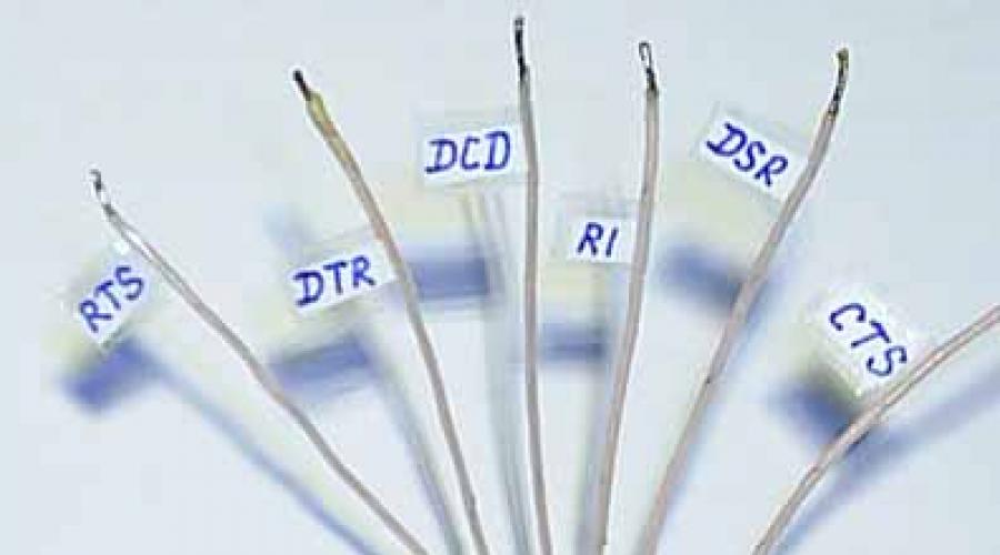
In general, the whole refinement consisted only in soldering to the corresponding legs of the microcircuit. To do this, it was first necessary to cut a window in a heat-shrinkable shell. Conformity of conclusions chips CH340G And RS232 signals see the table in Table 1.
As can be seen from the table, all signals, except for TXD and RXD, are on the same side of the microcircuit, but TXD and RXD are already output to the connector, so it was necessary to solder additional wires only on one side.
4. Testing the converter on the CH340G chip
To make sure that the module is working, and that it really ensures the operation of all the signals inherent in the COM port, I conducted its thorough testing. All tests passed, as they say, without a hitch, from which I conclude that this interface converter can be recommended for use in any devices and designs that require connection to a computer via RS232TTL. Including for use as a microcontroller programmer, as described in the article.
Testing was carried out using several scenarios for the Perpetuum M program. You can also test your own converter. Download (they are packed in one archive) and separately. Don't forget to check and if necessary change the port number in the scripts, otherwise they won't work. You can find out the port number in your case through the dispatcher Windows devices. At the beginning of each scenario (and they can be opened text editor, for example, notepad) you will see the line "PortName="COM3";". Instead of the number 3, put the number you need. For example, if a COM4 device appears in Device Manager when a module is connected, then in each scenario you need to specify "COM4" instead of "COM3".
Now I'll tell you more about the testing process. First I installed a jumper between the pins of the connector TXD And RXD so that the data from the transmitter immediately gets to the receiver. Thus, I "looped" the port so that it could transmit data to itself. This allows you to test both transmitter and receiver at the same time without connecting to another port. Then I ran the script "Testing a COM port by transferring a file through it" and selected a randomly turned up 653 KB file. File copying was successful. The copied file turned out to be absolutely identical to the original, which indicates the health of the receiver and transmitter of the UART module.
Next, I sequentially ran the scripts "Test TXD COM port output", "Test DTR COM port output" and "Test RTS COM port output", having previously connected a voltmeter to the corresponding output for each case. By entering zeros and ones into the program's dialog box, I made sure that they are successfully displayed on the outputs of the port. At the same time, it turned out that the TXD output displays logic levels without inversion, that is, when zero is output, low voltage, when outputting one - high, and the outputs DTR and RTS work with inversion. This should be taken into account when using this module in development.
Then I launched the "Test COM port inputs" script, which displays the status of four port inputs in real time: CTS, DSR, RI, DCD. Through a 5.6K resistor, I began to connect one by one each of the inputs either to a common wire (GND), or to a + 5V power line. It turned out the following. All inputs are operational, all of them give an inverse state during a software poll. All have a "pull-up" to the supply voltage, that is, the "hanging" input has a logical unit level and, accordingly, due to the inversion, it is read as "0" by the software. When connecting the input through a 5.6K resistor to the GND connector pin, each input easily goes into a logic zero state (programmatically read as "1"), which means that the resistance of the built-in "pullup" is at least an order of magnitude higher than 5.6K. Note that in modules based on the PL2303 chip, it is much more difficult to "kill" the built-in "pull-up" because of its low resistance.
To summarize: in addition to the possibility of serial data transfer via UART, we have three independently controlled outputs ( TXD, DTR, RTS), of which one is direct (TXD) and two are inverse, as well as four software polled inverse inputs with a "pull-up" to the supply voltage ( CTS, DSR, RI, DCD). If you plan to use the UART, then there will be only two independent outputs, since the TXD output is the signal from the UART transmitter. This does not apply to the inputs - there will still be four of them.
I must say about one more possibility, which allegedly allows you to change the level of a logical unit at the outputs by rearranging the jumper, depending on what voltage the microcircuits connected to this module are powered by: 5V or 3.3V. That is, the issue of matching levels is being resolved. I am writing about this "chip" with some disdain, because it is implemented in a strange way and does not inspire confidence. However, there is no special need for it, because harmonize levels between 5V and 3.3V is easy in other ways. And here's the thing. The module has three pins: 5V, VCC and 3.3V. With a jumper (it is even included in the kit) you can close 5V and VCC, or VCC and 3.3V. Or you can not set it at all, since with the complete absence of a jumper, everything works the same as if it is installed between VCC and 3.3V. The voltage on the 5V pin corresponds to the voltage of the +5V wire of the USB port. On the VCC pin, in the absence of a jumper, there is a voltage of about 3.8V, and on the 3.3V pin - about 3.2V. If the jumper is installed between 5V and VCC, then, in principle, there are no questions - TTL levels work, that is, a logical unit reaches five volts. But if you install a jumper between VCC and 3.3V, then questions arise, because in this case the voltage on the 3.3V pin rises to 3.8V (as it was on VCC before the jumper was installed), and the logical unit at the port outputs reaches 3.6 ...3.8V, which is too much for 3.3V. Without a jumper installed at the outputs, the unit level also reaches 3.6 ... 3.8V. Maybe nothing will burn out in this case, but the emphasis on the maximum permissible values \u200b\u200bis not the best factor for reliability.
5. Advantages and disadvantages of the CH340G converter
Of the shortcomings, I noted only two minor trifles that can be ignored with a competent approach. One of them is not entirely successful agreement with the 3.3V standard. But if you don't use 3.3V power, or you do, but the task of matching levels is not a problem for you, then everything is in order. The second minus is that all the LEDs of this module of the same color are red, which makes you remember their location if you want to navigate by them. But in real practice, the need for LEDs is not so great, and if they are still needed, then you can replace them with your own.
There are definitely more pluses. First of all, pleases the absence of problems with the drivers. As I said above, for microcircuits CH340 drivers for Windows installed automatically, including latest versions OS. But with converters on the PL2303 chip, everything is much more complicated. For old chips there are no drivers for new ones Windows versions. And the old microcircuits in the past were released by the sea. If I'm not mistaken, this was the reason why the developers did not support the old microcircuits. It seems that there was some kind of copyright problem - there were a lot of counterfeit microcircuits on the market. And then the developers, without fundamentally changing anything in the new microcircuit, changed only how it responds to the driver's request. Roughly speaking, to the question "Who are you?", the new microcircuit began to answer: "I am Vasya-plus." And if the driver receives the answer "I am Vasya", then he tells this microcircuit: "Go through the forest, Vasya without a plus." That is, technically new driver could well work with the old chip. As far as I know, there are even ways to get around this scourge - either the new driver is somehow forced to work with the old chip, or old driver"fastened" to the new OS.
Another convenience of this module is that the pin spacing of the CH340G chip is much larger, so soldering is much easier. This microcircuit has only 16 pins, among which basically only the most necessary, unlike the PL2303, where, apparently, there are pins for all occasions.

In my opinion, the high resistance of the "pull-up" of the inputs can also be considered a plus, which reduces the current of the logical zero, which means that it imposes fewer requirements on the signal source. If the requirements for protection against interference are very high, then you can easily organize an additional "pull-up" with an external resistor. When using this module as a role (see figure on the right), you can install all resistors with the same resistance (1K ... 4.3K). That is, it is not required to greatly underestimate the resistance at the CTS input.
I will add that in the past I spent comparative testing two converters on microcircuits PL2303 And CH340. The CH340 definitely won - in extreme modes it was much more difficult to get failures in working with it. Although it was a converter of a different design (adapter cord), but, as it seems to me, one can expect that other models of converters of the CH340 family are no less reliable.
If you have questions or comments on this article, write to or mail.ru (jkit box).
From correspondence with a site visitor
05/12/2017 Guest:
Hello Eugene.
.htm
I have the same converter (one to one).
The fact is that I need to reflash the FlySky i6 equipment to 10 channels. Initially, the jumper is in the "VCC-3V3" position. Did I understand correctly that it should be left as is? Sorry, but I'm off topic, that's why I'm asking this question. I don't want to burn anything.
14.05.2017
Hello Vladimir!
The answer to your question depends on specifications the equipment to which you connect the module on the CH340G. I have not encountered this equipment, so I can not say for sure. The link you gave gives a 404 error. But, even if the link worked, I would hardly have found the time to understand that equipment in detail. Try VCC-3V3 first. I don't think it will get any worse. Just in case, put 1 kΩ resistors in each signal wire (this is due to the fact that it is actually not 3.3 V, but more).
05/14/2017 Guest:
Hello Eugene.
Thanks for the advice! Indeed, it is better to start small.
And 1 kOhm is based on what current was it? (I just don’t know what currents flow through the signal wire, and I couldn’t find it anywhere)
17.05.2017
Hello Vladimir!
The question is worded incorrectly. Why do you need to know current? I took 1 kOhm "by eye", based on the fact that if somewhere, even in some way, 5 V is applied to the resistor in an emergency (and more, in theory, there should not be nearby), then the current will be 5 mA, which should not lead to negative consequences.
05/17/2017 Guest:
Hello Eugene.
He spoke about the current, because if it is close to zero, then there will be no voltage drop across the resistor and the output will be the same 3.6 V instead of 3.3 V. But I understood the meaning of your reinsurance, thanks for the comment.
19.05.2017
Hello Vladimir!
There are completely non-linear elements. And the point is not that the extra 0.3 V can break something with voltage, but just that even a small increase in voltage can suddenly cause a non-linearly fast increase in current. For example, protective diodes at the inputs, etc. may open. The resistor gives linearity to the circuit and prevents such a development of events. And normal currents are usually small (though not always), so a resistor shouldn't get in the way. An exception is a low-resistance pull-up at the input. Then the resistor will not allow it to "overcome" and will not work. This is detected by an oscilloscope, or even a voltmeter (in static mode).
05/19/2017 Guest:
Hello Eugene.
Thank you very much for the detailed explanation. Now at least I understand the mechanism of such protection. And then I already thought that the Chinese could deliberately overestimate the voltage, taking into account the drop when the load was turned on. Now it is clear that this is just a flaw.
20.05.2017
Hello Vladimir!
So that the voltage does not "sag" when the load is connected, the load capacity of the output is increased. "Extra" voltage is not added for this. Of course, 3.6V instead of 3.3V isn't that much, and it's unlikely that anything will break because of it. But it is dangerous to supply 3.8 V to the input of a microcircuit powered by a 3.3 V source, since the extra 0.5 V is already quite capable of opening a protective diode at the input, and if the output load capacity is high, it can damage the input connected to it . The "safety" resistor prevents this.
The use of materials from this site in publications is permissible only if these materials are accompanied by links to the source - site site indicating the author: E.A. Kotov. Copyrights are protected by the laws of the Russian Federation. Evgeny Kotov. 2017
- miniature board without case
- Possibility of power supply 5 V or 7...30 Volts
- has input / output TTL level Rx and Tx
- TTL level universal and compatible with 3.3V and 5V
- transistor buffers are used in the TTL input and output circuits to increase the reliability of the device
450 UAH
Supported protocols:
- TCP/IP to connect via socket and receive/transmit data;
- HTTP for settings via WEB-browser;
- Ping to test the connection.
Characteristics
| Parameter | Meaning |
| Ethernet interface | RJ-45 |
| TTL interface | Terminal block |
| TTL settings | 1 start bit, 8 data bits, no parity, 1 stop bit |
| TTL port speed | 300/600/1200/2400/4800/9600/19200/38400/57600/115200 bps |
| LED indication | "PWR" - the presence of power "TCP" - connection establishment via TCP/IP protocol "Rx" - data reception via TTL "Tx" - data transmission via TTL |
| Supply voltage | 5V / 7...30V DC |
| Maximum current consumption | 180 mA |
| Working temperature | 0..+70 С |
| Storage temperature | -55..+125 С |
| Dimensions WxHxD | 34x58x17 mm |
| Weight | 35g |
Each product is tested after production.
Related products
Power supply 5V 1A or 12V 1A

100 UAH- 5V
120 UAH- 12V
The installation archive can also be downloaded from our server:
Creating a COM Port
Install the program. Download. Go to the "Virtual Serial Port" tab. Set the number of the desired COM port, specify the inverter's IP address and port (9761 by default).
Click the "Create COM" button. After a few seconds, a COM port will be created with specified number and a connection to the transmitter will be established. The connection will be indicated by the "TCP" LED on the converter lighting up.
After that, everything written to the COM port will be transmitted to the TTL output, and received via TTL will be received on the COM port.

Transferring large amounts of information
Since the converter has a limited, compared to a PC, memory buffer for storing transmitted data, then with a volume of several kilobytes, it may overflow. To do this, set the "Strict Baudrate Emulation" option in the port driver settings. At the same time, the data transfer rate Ethernet networks will drop to the TTL baud rate and there will be no data loss.
Also, to exclude the insertion of service commands into the transmitted data, disable the "NVT Enable" option.

Permanent COM port
In order for the virtual COM port to be created as a permanent one, that is, after rebooting Windows continues to work, go to the "Settings" tab and set the "Create VSP Port when HW VSP Start-up" option.

Notes
1) Be sure to set the TTL port speed in the inverter (via Web browser).
2) Breaking communication with the converter via TCP/IP does not require reboots or any action. Communication is restored automatically after data transfer to the COM port.
Connecting with your own software
You can work with the converter using your own software. To do this, you develop a program that will establish a socket connection and will write / read data. The converter is used with a control device (computer) that implements the TCP/IP Socket server or Socket client function. The application software of the computer then establishes a connection or responds to a connection request. Further, the data received by the converter on the Socket is broadcast to the TTL (Tx) output, and the data received from the TTL (Rx) input is transmitted via a socket connection to the computer. Below are links to download test software for a computer that implements a Socket client, in case the converter is configured as a Socket server. The indicator light used indicates the presence of a socket connection and the transmission / reception of TTL data.
The diagram shows an example of connecting a converter to a TTL-level device.

PL2303HX is a small USB-to-Serial converter with built-in RS232 transceiver (UART interface). The microcircuit creates a virtual COM port on the computer, through which you can flash microcontrollers, as well as restore routers and set-top boxes.

Technical specifications
Supply voltage: 5V (from USB)
Interface 1: USB
Interface 2: TTL (0 to 5, Rx and Tx)
Output voltage, V: 3.3 and 5 (separate pins)
Dimensions: 50mm x 15mm x 8mm
Operating system support: Windows XP / 7 / 8 / 8.1 / 10.
General information about PL2303HX
The main chip per module is PL2303HX, which until 2012 was produced by Prolific Technology. Basically it's a converter. USB interface in UART with logic levels TTL, CMOS (0 V ... +5 V). On the one hand, a USB connector for connecting to a computer, and on the other, a five-pin UART connector (RX, TX and power outputs for + 5V and + 3.3V), for short circuit protection, the module is placed in a transparent heat shrink tube, circuit diagram PL2303HX is shown in the figure below.

Purpose of the LEDs:
P (Power) - power (solid on)
R (RxD) - received data
T (TxD) - transmitted data
From electrical circuit it can be seen that the power to the + 5V output goes directly from USB port, without protective elements, and the + 3.3V output is powered from the internal PL-2303 stabilizer, which can withstand current up to 150 mA. Official drivers Prolific for Windows 7, 8 and 10 does not work since. checks the originality of the PL-2303 chip, but it is possible to fix everything by looking at this .
Testing
For testing, you can use Terminal1_9_b" , download this program you can in this article.
Install, driver
We launch "Terminal1_9_b" on behalf of the administrator.
IN upper corner, choose " COM port" (can be viewed in the device manager) and click " Connect»

Below, enter an arbitrary value and click " -> send“, the TxD LED will light up briefly with each press.
Short the TxD and RxD pins together and press "-> Send", two LEDs, TxD and RxD, will briefly light up with each press, and the program will display the sent command.  Voltage 3.3V and 5V can be checked with a conventional multimeter
Links![]() Documentation PL2303HX
Documentation PL2303HX ![]() Driver for
Driver for