Technical characteristics of switches. Switching Basics Switch Bandwidth
Read also
- frame filtering speed;
- the speed of promotion of frames;
- throughput;
- transmission delay frame.
In addition, there are several switch characteristics that have the greatest impact on these performance characteristics. These include:
- switching type;
- the size of the frame buffer(s);
- switching matrix performance;
- the performance of the processor or processors;
- size switching tables.
Filtering rate and frame advance rate
The rate of filtering and frame advancement are the two main performance characteristics of the switch. These characteristics are integral indicators and do not depend on how the switch is technically implemented.
Filtering speed
- receiving a frame in its buffer;
- discarding a frame if an error is found in it (the checksum does not match, or the frame is less than 64 bytes or more than 1518 bytes);
- dropping a frame to avoid loops in the network;
- dropping a frame in accordance with the filters configured on the port;
- view switching tables to look up the destination port based on the frame's destination MAC address, and discard the frame if the frame's source and destination are connected to the same port.
The filtering speed of almost all switches is non-blocking - the switch manages to drop frames at the rate of their arrival.
Forwarding speed determines the rate at which the switch performs the following frame processing steps:
- receiving a frame in its buffer;
- view switching tables in order to find the destination port based on the MAC address of the recipient of the frame;
- frame transmission to the network through the found software switching table port of destination.
Both the filtration rate and the advance rate are usually measured in frames per second. If the characteristics of the switch do not specify for which protocol and for which frame size the values of filtering and forwarding rates are given, then by default it is considered that these indicators are given for the Ethernet protocol and frames of the minimum size, that is, frames with a length of 64 bytes (without a preamble) with data field of 46 bytes. The use of the minimum length frames as the main indicator of the switch processing speed is explained by the fact that such frames always create the most difficult operating mode for the switch compared to frames of another format with equal throughput of transmitted user data. Therefore, when testing a switch, the minimum frame length mode is used as the most difficult test, which should check the ability of the switch to work with the worst combination of traffic parameters.
Switch bandwidth (throughput) is measured by the amount of user data (in megabits or gigabits per second) transmitted per unit of time through its ports. Since the switch operates at the link layer, for it the user data is the data that is carried in the data field of the frames of the link layer protocols - Ethernet, Fast Ethernet, etc. The maximum value of the switch throughput is always reached on frames of maximum length, since when In this case, the share of overhead costs for frame overhead is much lower than for frames of the minimum length, and the time for the switch to perform frame processing operations per one byte of user information is significantly less. Therefore, a switch can be blocking for the minimum frame length, but still have very good throughput performance.
Frame transmission delay (forward delay) is measured as the time elapsed from the moment the first byte of the frame arrives at the input port of the switch until the moment this byte appears at its output port. The delay is the sum of the time spent buffering the bytes of the frame, as well as the time spent processing the frame by the switch, namely, viewing switching tables, making a forwarding decision, and gaining access to the egress port environment.
The amount of delay introduced by the switch depends on the switching method used in it. If switching is carried out without buffering, then the delays are usually small and range from 5 to 40 µs, and with full frame buffering - from 50 to 200 µs (for frames of the minimum length).
Switching table size
Maximum capacity switching tables defines the maximum number of MAC addresses that the switch can operate at the same time. IN switching table for each port, both dynamically learned MAC addresses and static MAC addresses that were created by the network administrator can be stored.
The value of the maximum number of MAC addresses that can be stored in switching table, depends on the application of the switch. D-Link switches for workgroups and small offices typically support a 1K to 8K MAC address table. Large workgroup switches support 8K to 16K MAC address tables, while network backbone switches typically support 16K to 64K addresses or more.
Insufficient capacity switching tables can cause the switch to slow down and clog the network with excess traffic. If the switching table is full and the port encounters a new source MAC address in an incoming frame, the switch will not be able to table it. In this case, the response frame to this MAC address will be sent through all ports (except for the source port), i.e. will cause flooding.
Frame buffer size
To provide temporary storage of frames in cases where they cannot be immediately transferred to the output port, the switches, depending on the implemented architecture, are equipped with buffers on the input, output ports or a common buffer for all ports. Buffer size affects both frame delay and packet loss rate. Therefore, the larger the amount of buffer memory, the less likely it is to lose frames.
Typically, switches designed to operate in critical parts of the network have a buffer memory of several tens or hundreds of kilobytes per port. The buffer common to all ports is usually several megabytes in size.
The topic of gigabit access is becoming more and more relevant, especially now, when competition is growing, ARPU is falling, and tariffs of even 100 Mbps are no longer surprising. We have long considered the issue of switching to gigabit access. Repulsed by the price of equipment and commercial feasibility. But competitors are not asleep, and when even Rostelecom began to provide tariffs of more than 100 Mbps, we realized that we could not wait any longer. In addition, the price for a gigabit port has significantly decreased and it has become simply unprofitable to install a FastEthernet switch, which in a couple of years will still have to be changed to a gigabit one. Therefore, they began to choose a gigabit switch for use at the access level.
We reviewed various models of gigabit switches and settled on two that are the most suitable in terms of parameters and, at the same time, meet our budget expectations. These are Dlink DGS-1210-28ME and .
Frame

The body of the SNR is made of thick, durable metal, which makes it heavier than the "competitor". The D-link is made of thin steel, which gives it a weight savings. However, it makes it more susceptible to external influences due to its lower strength.
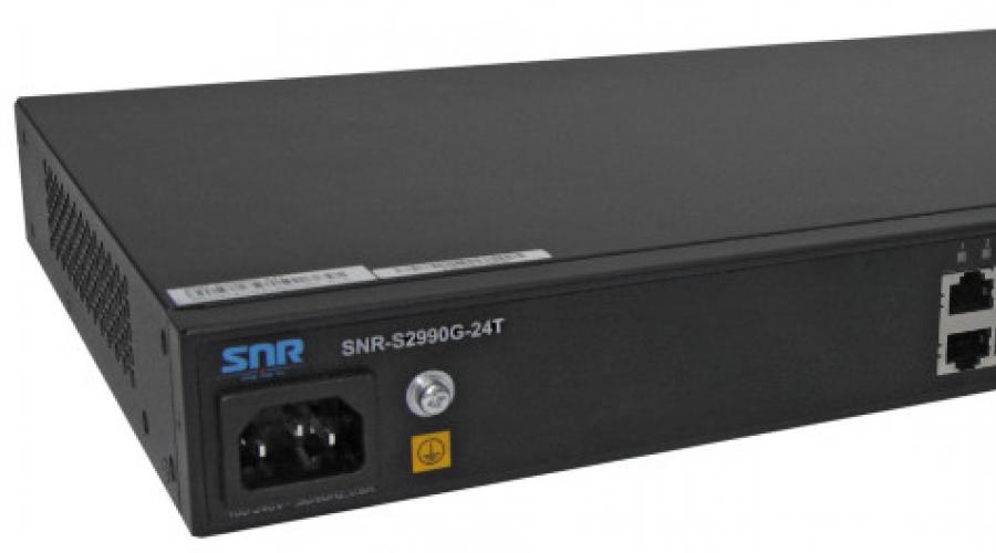
D-link is more compact: its depth is 14 cm, while that of SNR is 23 cm. The SNR power connector is located on the front, which undoubtedly facilitates installation.
Power supplies

D-link power supply

SNR power supply
Despite the fact that the power supplies are very similar, we still found differences. The D-link power supply is made economically, perhaps even too much - there is no lacquer coating on the board, the protection against interference at the input and output is minimal. As a result, according to Dlink, there are fears that these nuances will affect the switch's sensitivity to power surges, and operation in variable humidity, and in dusty conditions.
Switch board


Both boards are made neatly, there are no complaints about the installation, however, SNR has a better textolite, and the board is made using lead-free soldering technology. This, of course, is not about the fact that SNR contains less lead (than you can't scare anyone in Russia), but that these switches are produced on a more modern line.
In addition, again, as in the case of power supplies, D-link saved on varnish. SNR has a varnish coating on the board.
Apparently, it is implied that the working conditions of D-link access switches should be a priori excellent - clean, dry, cool .. well, like everyone else. ;)
Cooling
Both switches have a passive cooling system. D-link has larger radiators, and this is a definite plus. However, SNR has free space between the board and the back wall, which has a positive effect on heat dissipation. An additional nuance is the presence of heat-removing plates located under the chip, which remove heat to the switch case.
We conducted a small test - we measured the temperature of the heatsink on the chip under normal conditions:
- The switch is placed on a table at room temperature 22C,
- 2 SFP modules installed,
- We are waiting for 8-10 minutes.
The test results were surprising - D-link heated up to 72C, while SNR only reached 63C. What will happen to D-link in a tightly packed box in the summer heat, it's better not to think.

Temperature on D-link 72 degrees

On SNR 61 C, flight is normal
lightning protection
The switches are equipped with various lightning protection systems. D-link uses gas arresters. SNR has varistors. Each of them has its pros and cons. However, the response time of varistors is better, and this provides better protection for the switch itself and subscriber devices connected to it.
Summary
From D-link there is a feeling of economy on all components - on the power supply, board, case. Therefore, in this case, it gives the impression of a more preferable product for us.
Any System Administrator sooner or later faces the task of building or upgrading the local network of the enterprise. This issue should be approached very seriously and thoroughly, because. further carefree work depends on this.
How to choose a switch for their tasks, so as not to buy a new one?
Switch or in common switch is a network device that connects several computers into one single local area network. Modern switches have a very large number of functions that can greatly facilitate further work admin. The functioning of the entire local network and the operation of the enterprise as a whole depend on the correct choice of switches.
When choosing network equipment a novice system administrator is faced with a large number of obscure designations and supported protocols. This guide is written to fill this knowledge gap for beginners.
Introductory information
Many still do not see the difference between a switch and a hub. Realizing that the topic has already been discussed many times, I still wanted to start with it.
For switches, this rule is no longer relevant, because. modern switches even entry level in the course of work, a switching table is formed by typing a list of MAC addresses, and according to it, data is transferred. Each switch, after a short time of operation, "knows" on which port each computer on the network is located.
When you first turn on, the switching table is empty and the switch starts to work in learning mode. In the learning mode, the operation of the switch is identical to the operation of the hub: the switch, receiving data incoming on one port, forwards them to all other ports. At this time, the switch analyzes all passing ports and, as a result, compiles a switching table.
Features to Consider When Choosing a Switch
To make the right choice when buying a switch, you need to understand all the designations that are indicated by the manufacturer. Buying even the cheapest device, you can notice a large list of supported standards and functions. Each manufacturer of network equipment tries to indicate in the characteristics as possible more features to thereby distinguish your product from competitors and increase the final cost.
Common features of switches:
- Number of ports. The total number of ports to which various network devices can be connected.
The number of ports ranges from 5 to 48.
- Basic baud rate. This is the speed at which each switch port operates. Usually several speeds are indicated, for example, 10/100/1000 Mbps. This indicates that the port can operate at all specified speeds. In most cases, the switch supports the IEEE 802.3 Nway auto-sensing port speed.
When choosing a switch, consider the nature of the users connected to it.
- Internal Bandwidth. This parameter in itself does not play a big role. To choose the right switch, you should pay attention to it only in a pair with the total maximum speed of all ports of the switch (this value can be calculated independently by multiplying the number of ports by the base speed of the port). By comparing these two values, you can evaluate the performance of the switch at times of peak load, when all connected users are maximizing network connectivity.
For example, you are using a 16-port switch at 100 Mb/s with a throughput of 1 Gb/s. At peak times, 16 ports will be able to transmit the amount of information equal to:
16x100=1b00(Mb/s)=1.6(Gb/s)
The resulting value is less than the bandwidth of the switch itself. Such a switch is suitable in most cases of a small organization, where in practice the above situation can be encountered extremely rarely, but will not be suitable for an organization where large amounts of information are transmitted.
To choose the right switch, keep in mind that in reality, the internal throughput does not always correspond to the value declared by the manufacturer.
- Autonegotiation between Full-duplex or Half-duplex modes. In Full-duplex mode, data is transmitted in two directions at the same time. In Half-duplex mode, data can only be transmitted in one direction at a time. The auto-negotiation between modes feature avoids problems with using different modes on different devices.
- Auto MDI/MDI-X cable type detection. This function will automatically determine which standard the twisted pair cable was "crimped" to, allowing these 2 standards to work on the same LAN.
- Uplink port available. The Uplink port is designed for cascading switches, i.e. connecting two switches together. A crossover cable was used to connect them. Now such ports can only be found on older switches or on specific equipment. Roughly speaking, in modern switches, all ports work as Uplink.
- Stacking. Switch stacking refers to the combination of multiple switches into a single logical device. Stacking is advisable when you end up with a switch with a large number of ports (more than 48 ports). Different switch manufacturers use their proprietary stacking technologies, for example, Cisco uses StackWise stacking technology (32 Gbps bus between switches) and StackWise Plus (64 Gbps bus between switches).
When choosing a switch, you should give preference to devices that support stacking, because. this feature may be useful in the future.
- Rack Mountable. This means that the switch can be installed in a rack or in a wiring closet. The most widespread are 19-inch cabinets and racks, which have become an unwritten standard for modern network equipment.
Majority modern devices have such support, so when choosing a switch, you should not focus on this much attention.
- Number of expansion slots. Some switches have multiple expansion slots to accommodate additional interfaces. Gigabit modules using twisted pair and optical interfaces capable of transmitting data over fiber optic cable act as additional interfaces.
- MAC address table size. This is the size of the switching table that maps encountered MAC addresses to a particular switch port. If there is not enough space in the switching table, MAC addresses that have not been used for a long time are overwritten. If the number of computers in the network is much larger than the size of the table, then there is a noticeable decrease in the performance of the switch, because with each new MAC address, a computer is searched and a mark is entered in the table.
When choosing a switch, consider the approximate number of computers and the size of the switch's MAC address table.
- flow control(Flow control). IEEE 802.3x flow control provides protection against packet loss as it travels over the network. For example, a switch during peak loads, unable to cope with the data flow, sends a buffer overflow signal to the sending device and suspends receiving data. The sending device, receiving such a signal, stops data transmission until a positive response from the switch to resume the process follows. Thus, the two devices, as it were, "agree" among themselves when to transfer data, and when not.
Since this feature is present in almost all modern switches, it should not be emphasized when choosing a switch.
- jumbo frame. The presence of this feature allows the switch to operate with a larger packet size than specified in the Ethernet standard.
After each packet is received, some time is spent processing it. When using an increased packet size using Jumbo Frame technology, you can significantly save on packet processing time in networks where data transfer rates of 1 Gb / s and higher are used. With a lower speed, you should not expect a big win.
Jumbo Frame technology only works between two devices that both support it.
When choosing a switch, you should not focus on this function, because. it is present in almost all devices.
- Power over Ethernet (PoE). This technology transmits electrical current to power the switch over unused twisted-pair wires. IEEE 802.af standard.
- Built-in lightning protection. Some manufacturers build lightning protection technology into their switches. Such a switch must be grounded, otherwise the meaning of this additional function disappears.
Standard MDI:
Standard MDI-X:
Read about new hardware, news from computer companies and stay up to date with the latest achievements.
What kind of switches are there?
In addition to the fact that all existing switches differ in the number of ports (5, 8, 16, 24 and 48 ports, etc.) and data transfer rate (100Mb/s, 1Gb/s and 10Gb/s, etc.), Switches can also be divided into:
- Unmanaged switches are simple stand-alone devices that manage the data transfer on their own and do not have manual control tools. Some models of unmanaged switches have built-in monitoring tools (for example, some Compex switches).
Such switches are most widely used in "home" LANs and small businesses, the main advantage of which can be called a low price and offline work without human intervention.
The disadvantages of unmanaged switches are the lack of management tools and low internal performance. Therefore, it is not reasonable to use unmanaged switches in large enterprise networks, since the administration of such a network requires huge human efforts and imposes a number of significant restrictions.
- Managed switches- these are more advanced devices that also work in automatic mode, but in addition have manual control. Manual control allows you to very flexibly configure the operation of the switch and make life easier for the system administrator.
The main disadvantage of managed switches is the price, which depends on the capabilities of the switch itself and its performance.
Absolutely all switches can be divided into levels. The higher the level, the more complex the device, and therefore more expensive. The level of the switch is determined by the layer on which it operates. network model OSI.
To choose the right switch, you will need to decide at what network level you need to administer the LAN.
Separation of switches by levels:
- Layer 1 switch (Layer 1). This includes all devices that operate at layer 1 of the OSI networking model - physical level. Such devices include repeaters, hubs and other devices that do not work with data at all, but work with signals. These devices transmit information as if pouring water. If there is water, then they pour it further, if there is no water, then they wait. Such devices have not been produced for a long time and it is quite difficult to find them.
- Layer 2 switch (Layer 2). This includes all devices that operate at layer 2 of the OSI network model - link layer. These devices include all unmanaged switches and part of managed ones.
Layer 2 switches work with data not as a continuous flow of information (layer 1 switches), but as with separate pieces of information - frames ( frame or jarg. frames). They are able to analyze the received frames and work with the MAC addresses of the devices of the senders and recipients of the frame. Such switches "do not understand" the IP addresses of computers, for them all devices are named in the form of MAC addresses.
Layer 2 switches compile switching tables that map the MAC addresses of the network devices they encounter to specific switch ports.
Layer 2 switches support protocols:

- Layer 3 switch (Layer 3). This includes all devices that operate at layer 3 of the OSI networking model - network layer. These devices include all routers, part of managed switches, as well as all devices that can work with various network protocols: IPv4, IPv6, IPX, IPsec, etc. It is more expedient to attribute Layer 3 switches not to the category of switches, but to the category of routers, since these devices can already fully route passing traffic between different networks. Layer 3 switches fully support all the features and standards of Layer 2 switches. They can work with network devices by IP addresses. Layer 3 switch supports various connections: pptp, pppoe, vpn, etc.
- Layer 4 switch (Layer 4). This includes all devices that operate at layer 4 of the OSI network model - transport layer. These devices include more advanced routers that can already work with applications. Layer 4 switches use information that is contained in packet headers and refers to layers 3 and 4 of the protocol stack, such as source and destination IP addresses, SYN/FIN bits that mark the beginning and end of application sessions, and TCP/UDP port numbers for identification of traffic belonging to different applications. Based on this information, Layer 4 switches can make intelligent decisions about which session traffic to forward.
To choose the right switch, you need to imagine the entire topology of the future network, calculate the approximate number of users, select the data transfer rate for each section of the network, and start selecting equipment for a specific task.
Switch management
Smart Switches can be managed in a variety of ways:
- through SSH access. Connection to the managed switch is carried out via the secure SSH protocol using various clients (putty, gSTP, etc.). The configuration is done through the command line of the switch.
- through Telnet access to the switch console port. Connection to the managed switch is carried out using the Telnet protocol. As a result, we get access to the command line of the switch. The use of such access is justified only during the initial setup, since Telnet is an unsecured data transmission channel.
- through Web interface. The configuration is done via a web browser. In most cases, configuration via the Web interface does not allow you to use all the functions of network equipment that are fully available only in command line mode.
- via protocol SNMP. SNMP is a simple network management protocol.
A network administrator can control and configure several network devices at once from his computer. Thanks to the unification and standardization of this protocol, it becomes possible to centrally check and configure all the main components of the network.
To choose the right managed switch, you should pay attention to devices that have SSH access and the SNMP protocol. Undoubtedly, the Web interface facilitates the initial configuration of the switch, but almost always has fewer functions than the command line, so its presence is welcome, but not required.
Random 7 articles.
After the switching technology has attracted general attention and received high marks from specialists, many companies have begun to implement this technology in their devices, using various technical solutions for this. Many first-generation switches were similar to routers, that is, they were based on a general-purpose central processing unit connected to interface ports via an internal high-speed bus. However, these were rather trial devices intended for the development of the company's own switching technology, and not for conquering the market.
The main disadvantage of such switches was their low speed. A general-purpose processor could not cope with a large volume of specialized operations for sending frames between interface modules.
To speed up switching operations, specialized processors with specialized communication facilities were needed, as in the first Kalpana switch, and they soon appeared. Switches now use custom-designed LSIs that are optimized for basic switching operations. Often, several specialized LSIs are used in one switch, each of which performs a functionally complete part of the operations.
Currently, switches use one of three schemes for the interaction of their blocks or modules as a base:
♦ switching matrix;
♦ shared multi-input memory;
♦ common bus.
Often these three modes of interaction are combined in one switch.
Switch Fabric Switches
The switching matrix is the main and fastest way for the interaction of port processors, it was it that was implemented in the first industrial switch local networks. However, the implementation of the matrix is possible only for a certain number of ports, and the complexity of the circuit increases in proportion to the square of the number of switch ports.
The matrix consists of three levels of binary switches that connect their input to one of two outputs depending on the value of the tag bit. The first level switches are controlled by the first bit of the tag, the second by the second, and the third by the third.
The matrix can be implemented in another way, based on combinational circuits of a different type, but its feature is still the technology of switching physical channels. A well-known disadvantage of this technology is the lack of data buffering inside the switching matrix - if a composite channel cannot be built due to the busyness of the output port or intermediate switching element, then the data must be accumulated in their source, in this case, in the input block of the port that received the frame.
Common Bus Switches
Shared bus switches use a high-speed, time-sharing bus to communicate with the port processors. This switch architecture is based on a universal processor, but differs in that the bus is passive here, and specialized port processors play an active role.
In order for the bus not to be the bottleneck of the switch, its performance must be at least N/2 times higher than the rate of data entering the input blocks of the port processors. In addition, the frame must be transmitted over the bus in small parts, several bytes each, so that the transmission of frames between several ports occurs in pseudo-parallel mode, without introducing delays into the transmission of the frame as a whole. The size of such a data cell is determined by the switch manufacturer. Some vendors, such as LANNET (now a division of Madge Networks), have chosen the ATM cell, with its 48-byte data field, as the piece of data carried in a single bus operation. This approach facilitates the translation of LAN protocols into the ATM protocol if the switch supports these technologies.
The input block of the processor places a tag in a cell carried over the bus, which indicates the number of the destination port. Each port processor output block contains a tag filter that selects the tags destined for that port.
The bus, like the switching matrix, cannot perform intermediate buffering, but since the frame data is divided into small cells, there are no delays with the initial waiting for the availability of the output port in such a scheme.
Shared memory switches
The third basic port communication architecture is two-input shared memory.
The input blocks of the port processors are connected to the switched input of the shared memory, and the output blocks of the same processors are connected to the switched output of this memory. Switching input and output of shared memory is controlled by the output port queue manager. In shared memory, the manager organizes several data queues, one for each output port. The input processor blocks send requests to the port manager to write data to the queue of the port that corresponds to the destination address of the packet. The manager in turn connects the memory input to one of the input blocks of the processors and it rewrites part of the frame data to the queue of a certain output port. As the queues fill up, the manager also alternately connects the output of the shared memory to the output blocks of the port processors, and the data from the queue is rewritten to the output buffer of the processor.
The memory must be fast enough to support the data census rate between the N ports of the switch. The use of a shared buffer memory, flexibly distributed by the manager between individual ports, reduces the requirements for the size of the buffer memory of the port processor.
Combined Switches
Each of the described architectures has its own advantages and disadvantages, so these architectures are often used in combination with each other in complex switches.
The switch consists of modules with a fixed number of ports (2-8), made on the basis of a specialized LSI (ASIC), which implements the architecture of the switching matrix. If the ports between which the data frame must be transmitted belong to the same module, then the frame is transmitted by the module's processors based on the switching matrix available in the module. If the ports belong to different modules, then the processors communicate on a common bus. With this architecture, intra-module frame transfers will most often be faster than inter-module transfers, since the switch fabric is the fastest, albeit the least scalable, way for ports to communicate. The internal bus speed of the switches can reach several Gb / s, and for the most powerful models - up to 10-14 Gb / s.
It is possible to imagine other ways of combining architectures, for example, using shared memory modules for interaction.
Modular and Stack Switches
Structurally, switches are divided into:
♦ autonomous switches with a fixed number of ports;
♦ modular chassis-based switches;
♦ switches with a fixed number of ports, stacked.
The first type of switches is usually designed for organizing small workgroups.
Chassis-based modular switches are most often designed for network backbone applications. Therefore, they are performed on the basis of some combined scheme in which the interaction of modules is organized over a high-speed bus or on the basis of a fast shared memory of a large size. The modules of such a switch are based on the “hot swap” technology, that is, they can be replaced on the go, without switching off the switch, since the central communication device of the network should not have interruptions in operation. The chassis is usually equipped with redundant power supplies and redundant fans for the same purpose. In general, such switches resemble high-end routers or corporate multifunctional hubs, so sometimes they include, in addition to switching modules, repeater or router modules.
From a technical point of view, stack switches are of particular interest. These devices are switches that can work autonomously, as they are made in a separate case, but have special interfaces that allow them to be combined into common system which works as a single switch. In this case, the individual switches are said to form a stack.
Typically, this special interface is a high-speed bus that allows individual chassis to be combined like modules in a chassis-based switch. Since the distances between the cases are greater than between the modules on the chassis, the bus exchange rate is usually lower than that of modular switches: 200-400 Mb / s. Not very high exchange rates between stack switches are also due to the fact that stack switches usually occupy an intermediate position between switches with a fixed number of ports and chassis-based switches. Stack switches are used to create networks of workgroups and departments, so they do not really need ultra-high speed exchange buses and do not match their price range.
Cisco has come up with a different approach to stack organization. Its Catalyst 3000 switch (previously called the EtherSwitch Pro Stack) also has a dedicated 280 Mb/s high-speed stacking interface, but it connects the switches not to each other, but to a separate device containing an 8x8 switching matrix that organizes a higher-performance exchange between any pair of switches.
Switch Performance Specifications
The main characteristics of a switch that measure its performance are:
♦ filtering speed;
♦ routing speed (forwarding);
♦ throughput;
♦ frame transmission delay.
In addition, there are several switch characteristics that have the greatest impact on these performance characteristics. These include:
♦ the size of the frame buffer(s);
♦ internal bus performance;
♦ performance of the processor or processors;
♦ the size of the internal address table.
Filtering speed and promotion speed
The rate of filtering and frame advancement are the two main performance characteristics of the switch. These characteristics are integral indicators, they do not depend on how the switch is technically implemented.
The filter rate determines the rate at which the switch performs the following frame processing steps:
♦ receiving a frame in its own buffer,
♦ destroying a frame because its destination port is the same as its source port.
The forward rate determines the rate at which the switch performs the following frame processing steps:
♦ receiving a frame in its own buffer,
♦ lookup the address table to find the port for the frame's destination address,
♦ frame transmission to the network through the destination port found in the address table.
Both filtration rate and advance rate are usually measured in frames per second. If the characteristics of the switch do not specify for which protocol and for which frame size the values of filtering and forwarding rates are given, then by default it is considered that these indicators are given for the Ethernet protocol and frames of the minimum size, that is, frames with a length of 64 bytes (without a preamble), with a data field of 46 bytes. If the rates are given for a particular protocol, such as Token Ring or FDDI, then they are also given for the minimum length frames of that protocol (for example, 29-byte frames for the FDDI protocol). The use of minimum length frames as the main indicator of the speed of the switch is explained by the fact that such frames always create the most difficult operating mode for the switch compared to frames of another format with equal throughput of the transferred user data. Therefore, when testing a switch, the minimum frame length mode is used as the most difficult test, which should check the ability of the switch to work with the worst combination of traffic parameters for it. In addition, for packets of a minimum length, the filtering and forwarding speeds have a maximum value, which is of no small importance when advertising a switch.
The throughput of a switch is measured by the amount of user data transmitted per unit of time through its ports. Since the switch operates at the link layer, the user data for it is the data that is carried in the data field of the frames of the link layer protocols - Ethernet, Token Ring, FDDI, etc. The maximum value of the switch throughput is always achieved on frames of the maximum length, since in this case the share of overhead costs for frame overhead information is much lower than for frames of the minimum length, and the time for the switch to perform frame processing operations per one byte of user information is significant. less.
The dependence of the switch throughput on the size of transmitted frames is well illustrated by the example of the Ethernet protocol, for which, when transmitting frames of the minimum length, a transmission rate of 14880 frames per second and a throughput of 5.48 Mb / s is achieved, and when transmitting frames of the maximum length, a transmission rate of 812 frames per second is achieved. second and throughput of 9.74 Mb/s. Throughput drops by almost half when switching to frames of the minimum length, and this is without taking into account the time lost on processing frames by the switch.
Frame transmission delay is measured as the time elapsed from the moment the first byte of the frame arrives at the input port of the switch until the moment this byte arrives at the output port of the switch. Latency is the sum of the time spent buffering the frame's bytes, as well as the time spent processing the frame by the switch - looking up the address table, deciding whether to filter or forward, and accessing the egress port media.
The amount of delay introduced by the switch depends on the mode of its operation. If switching is carried out "on the fly", then the delays are usually small and range from 10 µs to 40 µs, and with full frame buffering - from 50 µs to 200 µs (for frames of the minimum length).
The switch is a multiport device, therefore, it is customary for it to give all the above characteristics (except for the frame transmission delay) in two versions. The first option is the total performance of the switch with simultaneous transmission of traffic through all its ports, the second option is the performance per one port.
Since with simultaneous transmission of traffic by several ports, there is a huge number of traffic options that differ in the size of frames in the stream, the distribution of the average intensity of frame streams between destination ports, the coefficients of variation in the intensity of frame streams, etc. etc., then when comparing switches in terms of performance, it is necessary to take into account for which traffic variant the published performance data were obtained. Unfortunately, for switches (as well as for routers) there are no generally accepted traffic test patterns that could be used to obtain comparable performance characteristics, as is done to obtain such performance characteristics of computing systems as TPC-A or SPECint92. Some labs that routinely test communications equipment have developed detailed descriptions conditions for testing switches and use them in their practice, however, these tests have not yet become general industrial.
Estimating the required overall switch performance
Ideally, a switch installed in a network transmits frames between nodes connected to its ports at the rate at which nodes generate these frames, without introducing additional delays and without losing a single frame. In real practice, the switch always introduces some delays in the transmission of frames, and may also lose some frames, that is, not deliver them to their destinations. Due to differences in internal organization different models switches, it is difficult to predict how a particular switch will transmit frames of a particular traffic pattern. The best criterion is still the practice when the switch is placed in a real network and the delays introduced by it and the number of lost frames are measured. However, there are simple calculations that can give you an idea of how the switch will behave in a real situation.
The basis for assessing how the switch will cope with the communication of nodes or segments connected to its ports is data on the average traffic intensity between network nodes. This means that you need to somehow estimate how many frames per second, on average, a node connected to port P2 generates a node connected to port P4 (traffic P24), a node connected to port P3 (traffic P23), and so on. , to the node connected to port P6. This procedure must then be repeated for the traffic generated by the nodes connected to ports 3, 4, 5 and 6. In general, the intensity of traffic generated from one node to another does not match the intensity of traffic generated in the opposite direction.
The result of traffic research will be the construction of a traffic matrix. Traffic can be measured in both frames per second and bits per second. Since then the required traffic values will be compared with the performance indicators of the switch, you need to have them in the same units. For definiteness, we will assume that in this example, the traffic and performance of the switch are measured in bits per second.
A similar matrix is built by the RMON MIB agents (Traffic Matrix variable) built into network adapters or other communication equipment.
In order for the switch to be able to support the required traffic matrix, several conditions must be met.
1. The overall performance of the switch should be greater
or equal to the total intensity of the transmitted traffic.
If this inequality is not met, then the switch will obviously not be able to cope with the flow of frames entering it, and they will be lost due to overflow of internal buffers. Since the average values of traffic intensities appear in the formula, no amount, even a very large size of the internal buffer or switch buffers, can compensate for too slow frame processing.
The overall performance of the switch is ensured by the sufficiently high performance of each of its individual elements - the port processor, switching matrix, common bus connecting modules, etc. Regardless of the internal organization of the switch and how its operations are pipelined, it is possible to determine fairly simple performance requirements for its elements that are necessary to support a given traffic matrix. Let's list some of them.
2. Nominal maximum protocol throughput
of each port of the switch must be at least the average intensity
of the total traffic passing through the port.
3. The processor performance of each port must be at least equal to the average intensity of the total traffic passing through the port. The condition is similar to the previous one, but instead of the nominal throughput of the supported protocol, it must use the throughput of the port's processor.
4. The performance of the internal bus of the switch must be no less than the average intensity of the total traffic transmitted between ports belonging to different switch modules.
This check should obviously be performed only for those switches that have an internal architecture of a modular type using a common bus for inter-module communication. For switches with a different internal organization, for example, with shared memory, it is easy to propose similar formulas to check the sufficient performance of their internal elements.
The above conditions are necessary for the switch to cope with the task on average and not lose frames constantly. If at least one of the above conditions is not met, then frame loss becomes not an episodic phenomenon at peak traffic values, but a permanent phenomenon, since even average traffic values exceed the capabilities of the switch.
Conditions 1 and 2 apply to switches with any internal organization, and conditions 3 and 4 are given as an example of the need to consider the performance of individual ports.
Because switch manufacturers try to make their devices as fast as possible, the overall internal throughput of a switch often exceeds by some margin the average of any traffic that can be routed to the switch ports according to their protocols. Such switches are called non-blocking, which emphasizes the fact that any variant of traffic is transmitted without reducing its intensity.
However, no matter what the overall performance of the switch, you can always specify for it such a distribution of traffic between ports that the switch cannot cope with and will inevitably begin to lose frames. To do this, it is enough that the total traffic transmitted through the switch for some of its output ports exceeds the maximum protocol throughput of this port. For example, if ports P4, P5, and P6 each send 5 Mbps to P2, then P2 will not be able to send traffic at an average rate of 15 Mbps to the network, even if the processor of this port has such a performance. The buffer of port P2 will fill up at a rate
15 Mb / s, and empty at a maximum rate of 10 Mb / s, so the amount of raw data will grow at a rate of 5 Mb / s, inevitably leading to overflow of any finite size buffer, and therefore to frame loss.
From the above example, it can be seen that switches can fully utilize their high internal performance only in the case of well-balanced traffic, when the probabilities of transmitting frames from one port to another are approximately equal. In case of traffic “skews”, when several ports send their traffic mainly to one port, the switch may not be able to cope with the task, not even due to insufficient performance of its port processors, but due to port protocol limitations.
The switch can also lose a large percentage of frames in cases where all of the above conditions are met, since they are necessary, but not sufficient for the timely promotion of frames received at the receiver ports. These conditions are not sufficient because they greatly simplify the process of passing frames through the switch. Orientation only to average values of flow rates does not take into account collisions that occur between the transmitters of the port and the network adapter of the computer, losses during the waiting time for access to the medium, and other phenomena that are caused by random moments frame generation, random frame sizes, and other random factors that significantly reduce the actual performance of the switch. Nevertheless, the use of the above estimates is useful, since it allows you to identify cases where the use of a particular switch model for a particular network is obviously unacceptable.
Since it is far from always possible to estimate the intensities of frame flows between network nodes, in conclusion of this section we present a relation that allows us to say that the switch has sufficient internal performance to support frame flows if they pass through all its ports with maximum intensity. In other words, we obtain the condition that for a given set of ports, the switch is non-blocking.
Obviously, a switch will be non-blocking if the overall internal throughput of the switch is equal to the sum of the maximum protocol throughputs of all its ports.
That is, if the switch has, for example, 12 Ethernet ports and 2 Fast Ethernet ports, then an internal capacity of 320 Mb / s will be enough to handle any distribution of traffic that enters the switch through its ports. However, this internal performance is redundant, since the switch is designed not only to receive frames, but also to forward them to the destination port. Therefore, all ports of the switch cannot constantly receive information from the outside at maximum speed - the average intensity of information leaving through all ports of the switch must be equal to the average intensity of information received. Therefore, the maximum rate of information transmitted through the switch in stable mode is equal to half the total throughput of all ports - each input frame is an output frame for some port. According to this statement, for the switch to function properly, it is sufficient that its internal overall performance is equal to half the sum of the maximum protocol bandwidths of all its ports.
Therefore, for a switch with 12 Ethernet ports and 2 Fast Ethernet ports, it is quite enough to have an average overall performance of 160 Mb / s, for normal operation on the transmission of any traffic distribution options that can be transmitted by its ports for a sufficiently long period of time.
Once again, it must be emphasized that this condition only guarantees that the internal elements of the switch - port processors, inter-module bus, central processor, etc. - deal with the processing of incoming traffic. An asymmetry in the distribution of this traffic across egress ports can always result in the inability to send traffic to the network in a timely manner due to port protocol limitations. To prevent frame loss, many switch manufacturers use proprietary solutions that allow “slowing down” the transmitters of nodes connected to the switch, that is, they introduce flow control elements without modifying the end node port protocols. These methods will be discussed below when considering the additional features of the switches.
In addition to the throughput of individual switch elements, such as port processors or a common bus, switch performance is affected by such parameters as the size of the address table and the size of the common buffer or individual port buffers.
Address table size
The maximum address table capacity determines the maximum number of MAC addresses that the switch can handle at the same time. Since switches most often use a dedicated processor unit with its own memory to store an instance of the address table to perform the operations of each port, the size of the address table for switches is usually given per port. Instances of the address table of different processor modules do not necessarily contain the same address information - most likely there will be not so many duplicate addresses, unless the traffic distribution of each port is completely equally probable among the other ports. Each port only stores the sets of addresses it has recently used.
The value of the maximum number of MAC addresses that the port processor can remember depends on the application of the switch. Workgroup switches typically only support a few addresses per port, as they are designed to form microsegments. Departmental switches must support several hundred addresses, and network backbone switches up to several thousand, typically 4K-8K addresses.
Insufficient address table capacity can slow down the switch and flood the network with excess traffic. If the port processor's address table is full, and it encounters a new source address in an incoming packet, it must evict any old address from the table and place a new one in its place. This operation itself will take some time from the processor, but the main performance loss will be observed when a frame arrives with a destination address that had to be removed from the address table. Since the frame's destination address is unknown, the switch must forward the frame to all other ports. This operation will create unnecessary work for many port processors, in addition, copies of this frame will also fall on those network segments where they are completely optional.
Some switch manufacturers solve this problem by changing the algorithm for handling frames with an unknown destination address. One of the switch ports is configured as a trunk port, to which all frames with an unknown address are sent by default. In routers, this technique has been used for a long time, allowing you to reduce the size of address tables in networks organized according to a hierarchical principle.
The transmission of a frame to the trunk port is based on the fact that this port is connected to the upstream switch, which has sufficient address table capacity and knows where to send any frame. An example of a successful frame transmission when using a trunk port is that the top-level switch has information about all network nodes, so the frame with the destination MAZ address transmitted to it through the trunk port is transmitted through port 2 to the switch to which the node with the MAZ address is connected .
Although the trunk port method will work effectively in many cases, it is possible to imagine situations where frames will simply be lost. One such situation is the following: the lower layer switch has removed from its address table the MAC8 address that is connected to its port 4 in order to make room for the new MAC3 address. When a frame arrives with a MAC8 destination address, the switch forwards it to trunk port 5, through which the frame enters the upper-level switch. This switch sees from its address table that the MAC8 address belongs to its port 1, through which it entered the switch. Therefore, the frame is not processed further and is simply filtered out, and, therefore, does not reach the destination. Therefore, it is more reliable to use switches with a sufficient number of address tables for each port, as well as support for a common address table by the switch management module.
Buffer volume
The switch's internal buffer memory is needed to temporarily store data frames in cases where they cannot be immediately transferred to the output port. The buffer is designed to smooth out short-term traffic ripples. After all, even if the traffic is well balanced and the performance of the port processors, as well as other processing elements of the switch, is sufficient to transfer average traffic values, this does not guarantee that their performance will be enough for very high peak load values. For example, traffic can arrive simultaneously at all switch inputs for several tens of milliseconds, preventing it from transmitting received frames to output ports.
To prevent frame losses when the average traffic intensity exceeds the average for a short time (and for local networks, traffic ripple values in the range of 50-100 are often found), the only remedy is a large buffer. As in the case of address tables, each port processor module usually has its own buffer memory for storing frames. The larger the amount of this memory, the less likely it is to lose frames during congestion, although if the traffic averages are unbalanced, the buffer will still overflow sooner or later.
Typically, switches designed to operate in critical parts of the network have a buffer memory of several tens or hundreds of kilobytes per port. It's good that this buffer memory can be reallocated between multiple ports, since simultaneous overloads on multiple ports are unlikely. An additional security feature can be a common buffer for all ports in the switch management module. Such a buffer is usually several megabytes in size.
Additional features of switches
Since the switch is a complex computing device with several processor modules, it is natural to load it in addition to performing the basic function of transmitting frames from port to port using the bridge algorithm and some additional functions that are useful in building reliable and flexible networks. The following describes the most common optional switch features that are supported by most communications equipment manufacturers.
Translation of link layer protocols
Switches can translate one link layer protocol to another, such as Ethernet to FDDI, Fast Ethernet to Token Ring, and so on. At the same time, they work according to the same algorithms as broadcasting bridges, that is, in accordance with the RFC 1042 and 802.1H specifications, which define the rules for converting frame fields of different protocols.
The translation of local area network protocols is facilitated by the fact that the most difficult work that routers and gateways often perform when connecting heterogeneous networks, namely the work of translating address information, does not need to be performed in this case. All LAN endpoints have unique addresses of the same format, regardless of the supported protocol. Therefore, the Ethernet NIC address is understood by the FDDI network adapter, and they can use these addresses in the fields of their frames without thinking that the node they are communicating with belongs to a network operating on a different technology.
Therefore, when negotiating local area network protocols, switches do not build host address mapping tables, but transfer destination and source addresses from a frame of one protocol to a frame of another protocol. The only conversion that may need to be performed is a bit-to-byte conversion if the Ethernet network conforms to a Token Ring or FDDI network. This is due to the fact that Ethernet networks have adopted the so-called canonical form of address transmission over the network, when the least significant bit of the most significant byte of the address is transmitted first. In FDDI and Token Ring networks, the most significant bit of the most significant byte of the address is always transmitted first. Since the lOOVG-AnyLAN technology uses either Ethernet or Token Ring frames, its translation into other technologies depends on which protocol frames are used in this segment of the lOOVG-AnyLAN network.
In addition to changing the order of bits when transferring address bytes, translation of the Ethernet protocol (and Fast Ethernet, which uses the Ethernet frame format) into the FDDI and Token Ring protocols includes the following (maybe not all) operations:
♦ Calculate the length of the data field of the frame and place this value in the Length field when transferring a frame from an FDDI or Token Ring network to an 802.3 Ethernet network (there is no length field in FDDI and Token Ring frames).
♦ Filling in frame status fields when transferring frames from FDDI or Token Ring network to Ethernet network. FDDI and Token Ring frames have two bits that must be set by the station to which the frame was intended - the Address A bit and the Frame Copy C bit. who generated it, brought the data feedback. When a switch transmits a frame to another network, there are no standard rules for setting the A and C bits in the frame that loops back to the source station. Therefore, switch manufacturers solve this problem at their own discretion.
♦ Drop frames from FDDI or Token Ring networks to Ethernet with a data field size greater than 1500 bytes, as this is the maximum data field size for Ethernet networks. In the future, it is possible to truncate the maximum size of the data field of FDDI or Token Ring networks by means of upper-level protocols, for example, TCP. Another solution to this problem is to support IP fragmentation by the switch, but this requires, firstly, the implementation of the network layer protocol in the switch, and secondly, the support of the IP protocol by the interacting nodes of the translated networks.
♦ Filling in the Type field (type of protocol in the data field) of the Ethernet II frame when frames arrive from networks
supporting FDDI or Token Ring frames that do not have this field. To store the Type field information, RFC 1042 suggests using the Type field of the LLC/SNAP frame header embedded in the data field of the MAC frame of the FDDI or Token Ring protocols. When reversed, the value in the Type field of the LLC/SNAP header is transferred to the Type field of the Ethernet II frame.
♦ Recalculation of the frame checksum in accordance with the generated values of the service fields of the frame.
Spanning Tree Algorithm Support
The Spanning Tree Algorithm (STA) allows switches to automatically determine the tree configuration of links in the network when ports are randomly connected to each other. As already noted, the normal operation of the switch requires the absence of closed routes in the network. These routes can be created by the administrator specifically to create redundant links, or they can occur randomly, which is quite possible if the network has multiple links and the cabling system is poorly structured or documented.
Switches supporting the STA algorithm automatically create an active tree link configuration (ie, a link configuration without loops) on the set of all network links. This configuration is called a spanning tree (sometimes referred to as a spanning or main tree), and its name gives the whole algorithm its name.
Switches find the spanning tree adaptively by exchanging service packets. The implementation of the STA algorithm in the switch is very important for working in large networks - if the switch does not support this algorithm, then the administrator must independently determine which ports need to be put in a blocked state in order to eliminate loops. In addition, if any connection, port or switch fails, the administrator must, firstly, detect the fact of the failure, and, secondly, eliminate the consequences of the failure by switching the backup connection to the operating mode by activating some ports.
Basic definitions
The network defines the root switch (root switch), from which the tree is built. The root switch can be selected automatically or assigned by the administrator. With automatic selection
The switch with the lower value of the MAC address of its control unit becomes invalid.
For each switch, a root port (root port) is defined - this is the port that has the shortest distance over the network to the root switch (more precisely, to any of the ports of the root switch). Then, for each network segment, a so-called designated port is selected - this is the port that has the shortest distance from this segment to the root switch.
The concept of distance plays an important role in spanning tree construction. It is by this criterion that a single port is selected that connects each switch to the root switch, and a single port that connects each network segment to the root switch. All other ports are placed in a standby state, that is, one in which they do not transmit normal data frames. It can be proved that with such a choice of active ports in the network, loops are eliminated and the remaining links form a spanning tree.
The distance to the root is defined as the total conditional time for data transfer from the port of this switch to the port of the root switch. In this case, it is considered that the time of internal data transfers (from port to port) by the switch is negligible, and only the time for data transfer over the network segments connecting the switches is taken into account. Segment conditional time is calculated as the time it takes to transfer one bit of information in 10-ns units between ports directly connected on a network segment. So, for an Ethernet segment, this time is equal to 10 conventional units, and for a 16 Mb/s Token Ring segment - 6.25. (The STA algorithm is not associated with any particular link layer standard; it can be applied to switches connecting networks of different technologies.)
To automatically determine the initial active configuration of the tree, all network switches after their initialization begin to periodically exchange special packets called Bridge Protocol Data Units (BPDUs), which reflects the fact that the STA algorithm for bridges was originally developed.
BPDUs are placed in the data field of link layer frames, such as Ethernet or FDDI frames. It is desirable that all switches support a common multicast address, through which frames containing BPDUs can be transmitted simultaneously to all switches in the network. Otherwise, BPDUs are broadcast.
The BPDU packet has the following fields:
♦ STA protocol version identifier - 2 bytes. Switches must support the same version of the STA protocol, otherwise an active loopback configuration may be established.
♦ BPDU type - 1 byte. There are two types of BPDU - a configuration BPDU, i.e. a request to become a root switch, based on which the active configuration is determined, and a reconfiguration notification BPDU, which is sent by a switch that detects an event requiring reconfiguration - link failure, port failure, change switch or port priorities.
♦ Flags - 1 byte. One bit contains the configuration change flag, the second bit contains the configuration change confirmation flag.
♦ Root switch ID - 8 bytes.
♦ Distance to root - 2 bytes.
♦ Switch ID - 8 bytes.
♦ Port ID - 2 bytes.
♦ Message lifetime - 2 bytes. Measured in units of 0.5 s, serves to detect stale messages. When a BPDU passes through a switch, the switch adds to the packet's lifetime the time it is delayed by that switch.
♦ The maximum message lifetime is 2 bytes. If a BPDU packet has a time to live greater than the maximum, then it is ignored by the switches.
♦ The hello interval at which BPDUs are sent.
♦ State change delay - 2 bytes. Minimum time for switch ports to become active. Such a delay is necessary to exclude the possibility of temporary occurrence of alternative routes due to non-simultaneous port state changes during reconfiguration.
The Reconfiguration Notification BPDU packet is missing all but the first two fields.
After initialization, each switch first considers itself the root. Therefore, it starts generating BPDU messages of the configuration type through all its ports every hello interval. In them, he specifies his identifier as the identifier of the root switch (and as this switch also), the distance to the root is set to 0, and the identifier of the port through which the BPDU is transmitted is indicated as the port identifier. Once a switch receives a BPDU that has a root switch ID less than its own, it stops generating its own BPDU frames and starts relaying only the frames of the new candidate root switch. When relaying frames, it increases the distance to the root, specified in the incoming BPDU, by the conditional time of the segment on which the given frame was received.
When relaying frames, each switch for each of its ports remembers the minimum distance to the root encountered in all BPDU frames received on that port. When the spanning tree configuration procedure is completed (in time), each switch finds its root port - this is the port that is closest to the other ports in relation to the root of the tree. In addition, switches select a designated port for each network segment in a distributed manner. To do this, they exclude their root port from consideration, and for all their remaining ports they compare the minimum distances to the root accepted for them with the distance to the root of their root port. If this distance is less than the accepted ones for a home port, it means that it is a designated port. All ports, except for the designated ports, are put into the blocked state, and the spanning tree is completed.
During normal operation, the root switch continues to generate service frames, and the remaining switches continue to receive them on their root ports and relay them to the designated ones. If the switch does not have assigned ports, then it still receives service frames on the root port. If the root port does not receive a service frame after the timeout expires, then it initializes a new spanning tree procedure.
Frame flow control methods
Some manufacturers use frame flow control techniques in their switches that are not found in LAN protocol standards to prevent frame drops due to congestion.
Since the loss of even a small fraction of frames usually greatly reduces the useful performance of the network, when the switch is overloaded, it would be rational to slow down the frame rate from the end nodes to the receivers of the switch in order to allow transmitters to unload their buffers at a faster rate. The algorithm for interleaving transmitted and received frames (frame interleave) should be flexible and allow the computer to transmit several of its own in critical situations for each received frame, and not necessarily reducing the reception intensity to zero, but simply reducing it to the required level.
To implement such an algorithm, the switch must have a mechanism to reduce the traffic intensity of the nodes connected to its ports. Some LAN protocols, such as FDDI, Token Ring, or lOOVG-AnyLAN, have the ability to change port priority and thus give priority to a switch port over a computer port. The Ethernet and Fast Ethernet protocols do not have this capability, so switch manufacturers for these very popular technologies use two methods of influencing end nodes.
These techniques are based on the fact that the end nodes strictly comply with all parameters of the medium access algorithm, but the switch ports do not.
The first method of "braking" the end node is based on the so-called aggressive behavior of the switch port when capturing the medium after the end of the transmission of the next packet or after a collision.
The switch can use this mechanism adaptively, increasing its aggressiveness as needed.
The second technique used by switch developers is the transfer of dummy frames to the computer in the case when the switch does not have frames in the buffer for transmission on this port. In this case, the switch may not violate the parameters of the access algorithm, honestly competing with the end node for the right to transmit its frame. Since in this case the medium will be equally likely to be at the disposal of either the switch or the end node, the intensity of frame transmission to the switch will, on average, be halved. This method is called the backpressure method. It can be combined with the aggressive media capture method to further suppress end node activity.
The backpressure method is not used to unload the processor buffer of the port directly connected to the suppressed node, but to unload either the shared buffer of the switch (if a shared shared memory architecture is used), or to unload the processor buffer of another port to which this port transmits its frames . In addition, the backpressure method can be used in cases where the port processor is not designed to support the maximum possible traffic for the protocol. One of the first examples of the application of the back pressure method is just related to such a case - the method was applied by LANNET in the LSE-1 and LSE-2 modules, designed for switching Ethernet traffic with a maximum intensity of 1 Mb / s and 2 Mb / s, respectively.
Traffic Filtering Capabilities of Switches
Many switches allow administrators to specify additional frame filtering conditions along with the standard frame filtering conditions according to address table information. User filters are designed to create additional barriers on the path of frames that restrict the access of certain user groups to certain network services.
If the switch does not support network and transport layer protocols that have fields indicating which service the transmitted packets belong to, then the administrator has to define the field by the value of which filtering should be performed in the form of an offset-size pair relative to the beginning of the data field of the data link layer frame. Therefore, for example, in order to prohibit a certain user from printing their documents on a certain NetWare print server, the administrator needs to know the position of the "socket number" field in the IPX packet and the value of this field for the print service, as well as know the MAC address user's computer and print server.
Typically, filtering conditions are written as Boolean expressions formed using the logical AND and OR operations.
Imposing additional filter conditions can degrade the performance of the switch because the evaluation of boolean expressions requires additional computation by the port processors.
In addition to general conditions, switches can support special filtering conditions. One of the very popular types of special filters are filters that create virtual segments.
The filter used by many manufacturers to protect a network built on the basis of switches is also special.
On-the-fly or buffered switching
The possibility of implementing additional functions is significantly affected by the method of transmitting packets - "on the fly" or with buffering. As the following table shows, most of the switch's advanced features require frames to be fully buffered before they are passed through the destination port to the network.
The average latency of on-the-fly switches under high load is explained by the fact that in this case the output port is often busy receiving another packet, so the newly arrived packet for this port still has to be buffered.
An on-the-fly switch can perform frame invalidity checks, but it cannot remove a bad frame from the network, since some of its bytes (and usually most) have already been transferred to the network. At the same time, with a small load, an on-the-fly switch significantly reduces the frame transmission delay, and this can be important for traffic that is sensitive to delays. Therefore, some manufacturers, such as Cisco, use an adaptive switch mode change mechanism. The main mode of such a switch is on-the-fly switching, but the switch constantly monitors traffic and, if the intensity of the appearance of bad frames exceeds a certain threshold, switches to full buffering mode.
Using different classes of service
This feature allows the administrator to assign different processing priorities to different types of frames. In this case, the switch maintains multiple queues of raw frames and can be configured, for example, so that it transmits one low priority packet for every 10 high priority packets. This feature can be especially useful on low speed lines and applications that have different requirements for acceptable delays.
Since not all link-layer protocols support a frame priority field, for example, Ethernet frames do not have one, the switch must use some additional mechanism to associate a frame with its priority. The most common way is to assign priority to switch ports. With this method, the switch puts the frame in the frame queue of the appropriate priority, depending on which port the frame entered the switch through. The method is simple, but not flexible enough - if not a separate node, but a segment is connected to the switch port, then all nodes of the segment receive the same priority. An example of a port-based class of service approach is 3Com's PACE technology.
It is more flexible to prioritize host MAC addresses, but this method requires a lot of manual work by the administrator.
Support for virtual networks
In addition to its main purpose - increasing the throughput of communications in the network - the switch allows you to localize information flows in the network, as well as control and manage these flows using custom filters. However, a custom filter can restrict frame transmissions only to specific addresses, and it transmits broadcast traffic to all network segments. This is required by the bridge algorithm, which is implemented in the switch, so networks created on the basis of bridges and switches are sometimes called flat - due to the absence of barriers to broadcast traffic.
The technology of virtual networks (Virtual LAN, VLAN) allows you to overcome this limitation.
A virtual network is a group of network nodes whose traffic, including broadcast traffic, is completely isolated from other network nodes at the link level. This means that it is not possible to send frames between different virtual segments based on the link layer address, regardless of whether the address is unique, multicast, or broadcast. At the same time, within the virtual network, frames are transmitted using switching technology, that is, only to the port that is associated with the frame's destination address.
It is said that the virtual network forms a broadcast traffic domain (broadcast domain), by analogy with the collision domain, which is formed by repeaters of Ethernet networks.
The purpose of virtual network technology is to facilitate the creation of independent networks, which must then communicate using network layer protocols. To solve this problem, before the advent of virtual network technology, separate repeaters were used, each of which formed an independent network. Then these networks were connected by routers into a single Internet.
When changing the composition of the segments (user transition to another network, splitting large segments), with this approach, it is necessary to physically reconnect the connectors on the front panels of repeaters or in cross panels, which is not very convenient in large networks - a lot of physical work, and there is also a high probability of error .
Therefore, to eliminate the need for physical re-switching, multi-segment repeaters began to be used. In the most advanced models of such repeaters, assigning a separate port to any of the internal segments is done programmatically, usually using a convenient graphical interface. Examples of such repeaters include Bay Networks' Distributed 5000 hub and 3Com's PortSwitch hub. Software assignment of a port to a segment is often referred to as static or configuration switching.
However, solving the problem of changing the composition of segments using repeaters imposes some restrictions on the network structure - the number of segments of such a repeater is usually small, so it is unrealistic to allocate a segment to each node, as can be done using a switch. Therefore, networks built on the basis of configuration switched repeaters are still based on the division of the data transmission medium between a large number of nodes, and therefore have much lower performance compared to networks built on the basis of switches.
When using virtual network technology in switches, two tasks are simultaneously solved:
♦ performance improvement in each of the virtual networks, since the switch forwards frames in such a network only to the destination node;
♦ Isolate networks from each other to manage user access rights and create protective barriers to broadcast storms.
Linking virtual networks to the internet requires network layer involvement. It can be implemented in a separate router, or it can also work as part of the switch software.
The technology for the formation and operation of virtual networks using switches has not yet been standardized, although it is implemented in a very wide range of switch models different manufacturers. The situation may soon change if the 802.1Q standard, which is being developed within the framework of the WEEE institute, is adopted.
In view of the lack of a standard, each manufacturer has its own virtual network technology, which, as a rule, is incompatible with the technology of other manufacturers. Therefore, virtual networks can be created so far on the equipment of one manufacturer. The only exceptions are virtual networks built on the basis of the LANE (LAN Emulation) specification, designed to ensure the interaction of ATM switches with traditional LAN equipment.
When creating virtual networks based on a single switch, the switch port grouping mechanism is usually used.
This is logical, since virtual networks built on the basis of one switch cannot have more than ports. If a segment built on the basis of a repeater is connected to one port, then it makes no sense to include the nodes of such a segment in different virtual networks - all the same, the traffic of these nodes will be common.
Creating virtual networks based on port grouping does not require a lot of manual work from the administrator - it is enough to assign each port to several pre-named virtual networks. Typically, this operation is performed by dragging the port icons onto the network icons.
The second method, which is used to form virtual networks, is based on the grouping of MAC addresses. When there are a large number of nodes in the network, this method requires a large number of manual operations from the administrator. However, it turns out to be more flexible when building virtual networks based on several switches than the port grouping method.
The problem that arises when creating virtual networks based on several switches that support the port grouping technique is as follows: if the nodes of a virtual network are connected to different switches, then a pair of ports must be allocated to connect the switches of each such network. Otherwise, if the switches are connected by only one pair of ports, information about the frame belonging to a particular virtual network will be lost during transmission from switch to switch. Thus, port trunking switches require as many ports for their connection as they support VLANs. Ports and cables are used in this way is very wasteful. In addition, when connecting virtual networks through a router, a separate cable is allocated for each virtual network in this case, which makes vertical wiring difficult, especially if the virtual network hosts are located on several floors.
Grouping MAC addresses into a network on each switch eliminates the need to link them across multiple ports, but requires a lot of manual tagging of MAC addresses on each switch in the network.
The two approaches described are based only on adding additional information to the address tables of the bridge and do not use the possibility of embedding information about the frame belonging to a virtual network in the transmitted frame. The remaining approaches use the existing or additional fields of the frame to save information and frame ownership when it moves between network switches. At the same time, there is no need to remember in each switch that all the MAC addresses of the internet belong to virtual networks.
If an additional field marked with a virtual network number is used, then it is used only when the frame is transmitted from switch to switch, and is removed when the frame is transmitted to the end node. At the same time, the “switch-switch” interaction protocol is modified, while the software and hardware of the end nodes remain unchanged. There are many examples of such proprietary protocols, but general disadvantage they have one - they are not supported by other manufacturers. Cisco has proposed using the 802.10 protocol header as a standard frame supplement for all LAN protocols to support security features. computer networks. The company itself uses this method in cases where switches are interconnected using the FDDI protocol. However, this initiative was not supported by other leading switch manufacturers, so until the adoption of the 802.1Q standard, proprietary virtual network tagging protocols will prevail.
There are two ways to build virtual networks that use the already existing fields to mark ownership of a virtual network frame, however, these fields do not belong to data link protocol frames, but to network layer packets or cells of ATM technology.
In the first case, virtual networks are formed based on network addresses, that is, the same information that is used when building internets in the traditional way - using physically separate networks connected to different ports of the router.
When a virtual network is formed based on network numbers, each switch port is assigned one or more network numbers, such as IP network numbers. Each IP network number corresponds to one virtual network. The end nodes must also support the IP protocol in this case. When transmitting frames between nodes belonging to the same virtual network, end nodes send data directly to the MAC address of the destination node, and indicate the IP address of their virtual network in the network layer packet. The switch in this case transmits frames based on the destination MAC address in the address table, while checking the validity of transmissions by matching the network IP number of the packet contained in the frame and the IP address of the destination port found in the address table. When a frame is transferred from one switch to another, its IP address is transferred along with the frame, which means that switches can be connected with only one pair of ports to support virtual networks distributed among several switches.
In the case when it is necessary to exchange information between nodes belonging to different virtual networks, the end node works in the same way as if it were in networks separated by a regular router. The end node forwards the frame to the default router by specifying its MAC address in the frame and the destination host's IP address in the network layer packet. The default router should be the indoor unit of the switch, which has a specific MAC address and IP address, just like a traditional router. In addition, it must have a routing table that specifies the egress port for all network numbers that exist on the common internet.
Unlike traditional routers, which have a different network number for each port, switches that support a network protocol to form virtual networks assign the same network number to multiple ports. In addition, the same port can be associated with several network numbers if switches communicate through it.
Often, switches do not support the automatic routing table building features that are supported by routing protocols such as RIP or OSPF. These switches are called Layer 3 switches to distinguish them from traditional routers. When using Layer 3 switches, routing tables are either manually created by the administrator (this is also often acceptable with a small number of virtual networks and the default route to a full-fledged router) or loaded from the router. According to the last scheme, a Catalist 5000 switch from Cisco interacts with routers from the same company.
If the switch does not support network layer functions, then its virtual networks can only be combined using an external router. Some companies make special routers for use with switches. An example of such a router is RND's Vgate router.
This router has one physical port to communicate with the switch port, but this port can support up to 64 MAC addresses, allowing the router to span up to 64 virtual networks.
The last way to organize virtual networks is associated with the use of ATM switches in the network. This method is based on using a separate virtual connection to send frames to each virtual network through ATM switches.
Switched network management
Switches are complex multifunction devices, which play a crucial role in modern networks. Therefore, support for centralized control and management functions implemented by the SNMP protocol and the corresponding agents is practically mandatory for all classes of switches (except, perhaps, desktop switches designed to work in very small networks).
To support SNMP management, the switches have a management module that contains an agent that maintains a database of management information. This module is often run on a separate powerful processor so as not to slow down the basic operations of the switch.
Traffic monitoring
Since overloads of port processors and other processing elements of the switch can lead to frame drops, the function of monitoring the distribution of traffic in a network built on the basis of switches is very important.
However, if the switch itself does not have a separate agent for each of its ports, then the task of monitoring traffic, traditionally solved in networks with shared environments by installing an external protocol analyzer in the network, becomes very complicated.
Traditionally, in traditional networks, a protocol analyzer (such as Network General's Sniffer) connected to a free port on the hub and saw all the traffic passing between any nodes on the network.
If the protocol analyzer is connected to a free port of the switch, then it will see almost nothing, since no one will send frames to it, and no other people's frames will be sent to its port either. The only type of traffic that the analyzer will see is the traffic of broadcast packets, which will be transmitted to all network nodes. In the case where the network is divided into virtual networks, the protocol analyzer will only see the broadcast traffic of its virtual network.
To ensure that protocol analyzers can still be used on switched networks, switch manufacturers equip their devices with the ability to mirror traffic from any port to a special port. A protocol analyzer is connected to a special port, and then a command is sent to the switch through its SNMP management module to map the traffic of any port to a special port.
The presence of the port mirroring function partially removes the problem, but leaves some questions. For example, how to view traffic on two ports at the same time, or how to view traffic on a full duplex port.
A more reliable way to monitor traffic passing through switch ports is to replace the protocol analyzer with RMON MIB agents for each switch port.
The RMON agent performs all the functions of a good protocol analyzer for the Ethernet and Token Ring protocols, collecting detailed information about traffic intensity, various types of bad frames, and lost frames, and independently building a time series for each captured parameter. In addition, the RMON agent can independently build cross-traffic matrices between network nodes, which are very necessary for analyzing the effectiveness of the switch.
Since an RMON agent that implements all 9 Ethernet object groups is very expensive, vendors often implement only the first few RMON MIB object groups to reduce the cost of the switch.
Virtual network management
Virtual networks create problems for traditional SNMP-based management systems, both in their creation and in monitoring their operation.
Typically, creating virtual networks requires special software manufacturer that runs on a control system platform such as HP Open View. The platforms of management systems themselves cannot support this process, mainly due to the lack of a standard for virtual networks. It is hoped that the advent of 802.1Q will change the situation in this area.
Monitoring virtual networks also creates challenges for traditional management systems. When creating a network map that includes virtual networks, you need to display both the physical structure of the network and its logical structure, corresponding to the connections of individual virtual network nodes. At the same time, at the request of the administrator, the management system should be able to display the correspondence of logical and physical links in the network, that is, all or individual paths of virtual networks should be displayed on one physical channel.
Unfortunately, many management systems either do not display virtual networks at all, or do so in a very inconvenient way for the user.
Typical Switch Applications
Switch or hub?
When building small networks that make up the lower level of the corporate network hierarchy, the question of using one or another communication device is reduced to the question of choosing between a hub or a switch.
In answering this question, several factors must be taken into account. Of course, the cost for the port, which must be paid when choosing a device, is of no small importance. From technical considerations, first of all, it is necessary to take into account the existence
traffic distribution between network nodes. In addition, it is necessary to take into account the prospects for the development of the network: whether multimedia applications will be used in the near future, whether the computer base will be modernized. If yes, then today it is necessary to provide reserves for the bandwidth of the communication equipment used. The use of intranet technology also leads to an increase in the volume of traffic circulating in the network, and this must also be taken into account when choosing a device.
When choosing a device type - hub or switch - you also need to determine the type of protocol that its ports will support (or protocols, if in question about the switch since each port can support a different protocol).
Today, the choice is made between protocols of two speeds - 10 Mb / s and 100 Mb / s. Therefore, when comparing the applicability of a hub or switch, you should consider a hub option with 10 Mbps ports, a hub option with 100 Mbps ports, and several switch options with different combinations of speeds on its ports.
By using the cross-traffic matrix technique to analyze the performance of a switch, it is possible to evaluate whether a switch with known port capacities and overall throughput will be able to support network traffic given as a matrix of average traffic rates.
Let's now consider this technique to answer the question of the applicability of the switch in a network with one server and several workstations interacting only with the server. This network configuration is often found in networks of scale working group, especially on NetWare networks where standard client shells cannot communicate with each other.
The cross-traffic matrix for such a network has a degenerate form. If the server is connected, for example, to port 4, then only the 4th row of the matrix and the 4th column of the matrix will have non-zero values. These values correspond to the outgoing and incoming traffic of the port to which the server is connected. Therefore, the conditions for the applicability of a switch for a given network are reduced to the possibility of transmitting all network traffic by the port of the switch to which the server is connected.
If the switch has all ports with the same bandwidth, for example, 10 Mb / s, then in this case the port bandwidth of 10 Mb / s will be distributed among all computers on the network. The ability of the switch to increase the overall network throughput is not in demand for such a configuration. Despite the micro-segmentation of the network, its bandwidth is limited by the bandwidth of the protocol of one port, as in the case of a hub with 10 Mbps ports. A small gain when using a switch will be achieved only by reducing the number of collisions - instead of collisions, frames will simply enter the queue to the transmitter of the switch port to which the server is connected.
In order for the switch to work more efficiently in networks with a dedicated server, switch manufacturers produce models with one high-speed 100 Mb / s port for connecting a server and several low-speed 10 Mb / s ports for connecting workstations. In this case, 100 Mb/s is already distributed between workstations, which makes it possible to serve 10 - 30 stations in a non-blocking mode, depending on the intensity of the traffic they generate.
However, a hub that supports a 100 Mbps protocol such as Fast Ethernet can compete with such a switch. Its cost per port will be slightly lower than the cost per port of a switch with one high-speed port, and the network performance is about the same.
It is obvious that the choice of a communication device for a network with a dedicated server is rather complicated. To make a final decision, one must take into account the prospects for the development of the network in relation to the movement towards balanced traffic. If the network may soon have interaction between workstations, or a second server, then the choice must be made in favor of a switch that can support additional traffic without prejudice to the main one.
The distance factor can also play in favor of the switch - the use of switches does not limit the maximum network diameter to 2500 m or 210 m, which determine the size of the collision domain when using Ethernet and Fast Ethernet hubs.
Switch or router?
When constructing the upper, backbone levels of the corporate network hierarchy, the problem of choice is formulated differently - a switch or a router?
The switch makes the transfer of traffic between network nodes faster and cheaper, but the router more intelligently filters traffic when connecting networks, not passing unnecessary or bad packets, and also reliably protecting networks from broadcast storms.
Due to the fact that enterprise-class switches can support some network-layer functions, the choice is increasingly made in favor of the switch. In this case, the router is also used, but it often remains in the local network in a single copy. This router usually serves both to connect the local network with the global ones, and to combine virtual networks built using switches.
In the center of networks of buildings and floors, switches are increasingly being used, since only with their use it is possible to transfer several gigabits of information per second at an affordable price.
Line drawn to a point on a switch
With all the variety of block diagrams of networks built on switches, they all use two basic structures - a backbone drawn to a point and a distributed backbone. Based on these basic structures, various structures of specific networks are then built.
A collapsed backbone is a structure in which nodes, segments, or networks are joined together on the internal backbone of a switch.
The advantage of this structure is the high performance of the line. Since for the switch, the performance of the internal bus or circuit shared memory, combining port modules of several Gb / s is not uncommon, then the network backbone can be very fast, and its speed does not depend on the protocols used in the network and can be increased by replacing one switch model with another.
A positive feature of such a scheme is not only the high speed of the backbone, but also its protocol independence. On the internal backbone of the switch, data of various protocols, such as Ethernet, FDDI, and Fast Ethernet, can be transmitted simultaneously in an independent format. Connecting a new node with a new protocol often does not require replacing a switch, but simply adding an appropriate interface module that supports this protocol.
If only one node is connected to each switch port in such a scheme, then such a scheme will correspond to a micro-segmented network.
Distributed backbone on switches
In networks of large buildings or campuses, the use of a collapsed backbone structure is not always rational or even possible. This structure leads to extended cable systems that connect the end nodes or switches of workgroup networks with a central switch, the bus of which is the backbone of the network. The high density of cables and their high cost limit the use of a point-to-point backbone in such networks. Sometimes, especially in campus networks, it is simply not possible to bundle all the cables into one room due to link length restrictions imposed by the technology (for example, all implementations of twisted-pair LAN technologies limit cable lengths to 100 m).
Therefore, in local networks covering large areas, another option for building a network is often used - with a distributed backbone.
A distributed backbone is a shared network segment that supports a specific protocol, to which workgroup and department network switches are connected. In the example, a distributed backbone is built on the basis of a double FDDI ring, to which floor switches are connected. Floor switches have a large number of Ethernet ports whose traffic is translated into FDDI protocol traffic as it travels across the backbone from floor to floor.
The distributed backbone simplifies communications between floors, reduces cabling costs, and overcomes distance limitations.
However, the trunk speed in this case will be significantly less than the trunk speed on the switch's internal bus. Moreover, this speed is fixed and does not currently exceed 100 Mb / s. Therefore, a distributed backbone can only be used when there is low traffic intensity between floors or buildings.
Switch Models
The market for switches today is very extensive, so in this summary we will dwell only on some popular models of switches of various classes. Typically, switches are primarily divided into classes according to their areas of application - desktop switches, workgroup switches, departmental switches, and backbone (corporate switches). Each class of switches has its own distinctive features.
Desktop switches
♦ Fixed number of ports;
♦ All ports operate at the same speed;
♦ Are used for the organization of peer-to-peer connections of high-speed workstations;
♦ Switching mode - "on the fly";
♦ Most often do not contain an SNMP management module, and also do not support the Spanning Tree algorithm.
Example: 3Com LinkSwitch 500.
Workgroup switches
♦ Have at least 1 high speed port (FDDI, Fast Ethernet, ATM);
♦ Broadcast protocols;
♦ Typically managed by SNMP, support Spanning Tree algorithm;
♦ Switching mode - with buffering.
Examples: 3Com LinkSwitch family (except Model 500), SMC TigerSwitch XE, Bay Networks Ethernet Workgroup Switch.
Departmental and data center switches
♦ Modular design;
♦ Support for multiple protocols;
♦ Built-in fault tolerance:
♦ redundant power supplies;
♦ hot-swap modules.
♦ Custom filters;
♦ Support for virtual segments;
Examples: 3Com LANplex 2500, SMC ES/1, Bay Networks Lattis-Switch System 28115.
Building/Campus Backbone Switches
♦ Same features as department switches;
♦ Chassis with a large number of slots (10 - 14);
♦ Internal bandwidth 1 - 10 Gb/s;
♦ Support for 1-2 routing protocols (local interfaces) to form virtual networks.
Examples: 3Com LANplex 6000, Cabletron MMAC Plus, LANNET LET-36, Cisco Catalist 5000, Bay Networks System 5000.
Cisco Systems Catalyst Switches
The Catalyst 5000 switch is the top model of the Catalyst family. It is a modular, multi-layer switching platform that provides a high level of performance, providing the ability to create dedicated connections on Ethernet networks at speeds of 10 and 100 Mbps, as well as to organize interaction with FDDI and ATM networks.
The Catalyst 5000 chassis has 5 slots. One slot installs a Supervisor Engine that controls access to a switchable fabric that can switch more than 1 million packets per second. The module supports local and remote management functions and has two Fast Ethernet ports that can be used to connect network servers or cascade Catalyst 5000 devices. The remaining connectors can be used to install the following modules:
♦ 24 10Base-T ports;
♦ 12 10Base-FL ports;
♦ 12 100Base-TX ports;
♦ 12 100Base-FX ports;
♦ 1 DAS CDDI/FDDI port (no more than 3 modules per chassis);
♦ 1 port 155 Mb/s ATM (no more than 3 modules per chassis).
A single Catalyst 5000 appliance can support up to 96 switched Ethernet ports and up to 50 switched Fast Ethernet ports.
Virtual networking is supported both within a single Catalyst 5000 appliance and across multiple appliances based on port trunking. You can create up to 1000 virtual networks for multiple Catalyst 5000 devices connected by Fast Ethernet, CDDI/FDDI, or ATM interfaces. Any Fast Ethernet interface can be configured as an InterSwitch Link (ISL) interface to support multiple virtual networks. The ISL interface is Cisco's proprietary solution for passing information between switches about virtual networks.
All virtual networks support the IEEE 802.Id Spanning Tree protocol to provide fault-tolerant connections. When using the ATM interface to connect switches, virtual networking is supported based on the LANE specification through virtual connections. The FDDI interface supports virtual networks using the 802.10 specification.
A distinctive feature of the Catalyst switches is the implementation of switching at the 3rd layer of the OSI model, which allows you to combine virtual networks within the device (this requires additional software).
The switching control module maintains three levels of frame queues with different priorities, with priorities assigned to each port separately. This allows you to efficiently serve multimedia traffic.
A large buffer (192 KB per port) ensures the storage and transmission of information during peak loads.
The Catalyst 3000 system is the original implementation of a stacking architecture for switches. This architecture is supported by two types of devices:
♦ Catalyst 3000 switch with 16 10Base-T ports, one AUI port, and two expansion slots. Expansion modules can have either 1 100Base-TX port or 3 10Base-FL ports or 4 10Base-T ports or 1 ATM port. The monitoring port mirrors any data port to an external port.
♦ Catalyst Matrix - An 8-port switching matrix that can be used to stack up to 8 Catalyst 3000 switches to create a single switching center.
Catalyst 3000 switches connect to the Catalyst Matrix through dedicated 280 Mbps ports. The bus performance of the Catalyst Matryx is 3.84 Gb/s.
The switch runs IOS and uses two switching algorithms - cut-throw and store-and-forward.
The Catalyst 3000 stack supports up to 64 virtual networks and allows you to filter traffic by source and destination address. The maximum number of MAC addresses is up to 10K per device.
Spanning Tree algorithm and SNMP management are supported.
SMC EliteSwitch ES/1 Switch
SMC Corporation (now part of Cabletron's Switch Division) designed the EliteSwitch ES/l as an effective tool for building a medium-sized backbone network. The ES/1 switch combines the functions of a high-performance Ethernet/Token Ring/FDDI switch and a local router to create IP and IPX virtual networks based on virtual switched workgroups. Thus, in one device, the switching and internetworking functions necessary to build a structured local area network based on an internal high-speed bus are combined. The switch also supports global connections with a point-to-point topology via T1 / E1 lines, allowing you to connect several local networks built on its basis with each other.
The ES/1 switch uses buffered switching technology, which allows it to translate link-layer protocols, perform custom filtering, statistics collection, and local routing.
ES/1 switch organization
The SMC Modular Hub ES/1 is a chassis-type device with a rear communication board, on which an internal bus with a throughput of 800 Mb/s is made. The Packet Processing Engine includes two processor modules equipped with high-performance AMD 29000 RISC processors. One of the processors is designed to transmit packets (that is, it performs switching functions), and the other performs administration - filtering on the ports of the hub in accordance with masks entered by the administrator and controls all the logic of the hub. Both processors have access to a shared 4 MB of memory.
As already noted, the packet processing module of the ES/1 switch is built on a dual processor architecture, with each of the processors responsible for its own functions. However, if one of them fails, the second processor will take over all the functions of the first. In this case, the switch as a whole will continue to operate normally, its performance may only slightly decrease.
The address table of the hub can store up to 8192 MAC addresses.
The software that controls the operation of the ES/1 hub is duplicated in two banks of Flash memory. Firstly, this allows you to upgrade new software versions without stopping the concentrator from performing its main packet switching functions, and secondly, a failure when loading new software from the Flash memory bank will not lead to the concentrator failure, since the software from the first memory bank will remain operational and the hub will automatically reboot it.
Network communication modules are inserted into the slots of the hub, while plug-and-play automatic self-configuration technology is implemented. Each module is equipped with its own RISC processor, which converts incoming packets into a protocol-independent form (this means that only the data block, the destination and source addresses, and network protocol information are stored) and passes them further along the internal bus to the packet processing unit .
The fault tolerance of the modules is ensured by the presence in each of them of a special sensor that sends a warning to the operator's console when the temperature approaches a critical level. This can happen, for example, due to dust in the air filters. If the temperature continues to rise and exceeds the second threshold value, the module is automatically turned off from the power supply to prevent failure of the element base. When the temperature drops, the module will automatically continue to work.
An important feature of the ES/1 concentrator is the built-in protection system against "storms" of broadcast packets (broadcast storm). The ES/1 concentrator software allows you to set a limit on the frequency of arrival of such packets on each concentrator port, if it is exceeded, broadcast packets are no longer transmitted to other network segments, which keeps them operational.
Filtering and virtual workgroups
Using the port masking mechanism, the administrator can create virtual workgroups to protect against unauthorized access and improve LAN performance by redistributing information flows.
Filtering can be enabled for incoming and / or outgoing packets, by MAC address or by the entire segment, and so on. In total, the mask can contain up to 20 conditions, combined by boolean operands "AND" and "OR". It is clear that each packet arriving at the switch port must be additionally checked for compliance with filtering conditions, which requires additional computing resources and can lead to performance degradation. The fact that in ES/1 one of the two processors is dedicated to checking filtering conditions ensures that the switch maintains high performance with masks entered by the administrator.
Along with equipment failures, operating personnel errors can disrupt the correct operation of the LAN. Therefore, we especially note one more interesting virtual filtering mode of the ES/1 switch. In this mode, filtering is not physically enabled, but statistics are collected on packets that satisfy the filtering conditions. This allows the LAN administrator to predict his actions in advance before the filters are physically turned on.
ES/1 hub communication modules
ES/1 supports up to five modules. You can choose any combination of modules for Ethernet, Token Ring, and FDDI, as well as high-speed T1/E1 and T3/E3 lines. All modules, including power supplies, can be replaced without disconnecting the mains and powering off the central unit. Each module maintains a set of configurable parameters to improve manageability and collect statistics.
♦ QEIOM (Quad Ethernet I/O Module)
Up to four independent Ethernet segments can be connected to this module. Each segment can transmit and receive information at a typical Ethernet throughput of 14880 packets per second. ES/1 provides connectivity between these four segments as bridges and routers, as well as with the rest of the network. These modules come with different types of connectors: AUI, BNC, RJ-45 (twisted pair) and ST (fiber optic cable).
♦ QTIOM (Token Ring I/O Module)
Up to four 4 or 16 Mbps Token Ring networks are connected through the QTIOM module. The module supports all major Token Ring network protocols - IBM Source Routing, Transparent Bridging and Source Routing Transparent - and provides "transparent" interaction of Token Ring networks with networks of other types, such as Ethernet or FDDI. The module is available in shielded and unshielded twisted pair versions.
♦ IFIOM (Intelligent Dual Attached FDDI I/O Module)
The IFIOM module connects the fiber optic segment of the FDDI network to the ES/1 and provides transparent communication between different types networks. It supports all the functions of a Dual Attached Station FDDI station. This module also supports an external optical bypass switch, which provides increased network resiliency in the event of an ES/1 failover. It is supplied in various modifications: for single-mode and multimode fibers and in their combinations.
♦ CEIOM24 (24-Port Concentrator Ethernet I/O Module)
This module includes a 24-port twisted-pair Ethernet hub. It increases network performance at a cost less than that of a comparable external device. Its ports are grouped into a single independent Ethernet segment and interact with other modules through the ES/1 switch/router.
♦ SHOM (High-Speed Serial Interface I/O Module)
NUM allows you to connect networks to remote LANs via high-speed communication lines using the HSSI protocol at speeds up to 52 Mb / s. The PPP protocol is supported.
SNMP manageability
The ES/1 Modular Hub can be controlled from any standard system management based on HaSNMP-npo-tocol, including: HP OpenView, IBM NetView/6000, Sun NetManager, etc. For a graphical representation of the front panel of the hub, special software modules from SMC of the EliteView family are added to the listed management consoles. In addition, there is a Windows version of monitoring and control software: EliteView for Windows.
Typical ES/1 Concentrator Usage Patterns
♦ Creating a degenerate backbone (Collapsed Backbone)
The degenerate backbone inside the switch is used in large corporate networks. Several large segments of the local network are connected to the ports of the hub, the bus of which in this case acts as the main backbone with a throughput of hundreds of Mb / s. This approach makes it possible to increase network bandwidth by several times compared to the traditional use of bridges on each network segment. At the same time, the possibilities of centralized management of all elements of the corporate network are significantly increased.
♦ Dedicated Ethernet channel
This scheme for connecting devices to the ports of switched hubs is most often used to create a high-speed backbone (with a guaranteed throughput of 10 Mb / s) between the hub and a local network server (usually a file server or database server). Modular hubs allow organizing, if necessary, connecting the server via a high-speed FDDI or Fast Ethernet channel.
♦ Broadcast switching
Switching in ES/1 is based on Synchronous Protocol Independent technology, which supports the basic technologies of local area networks, allowing translation between frames of various formats. Therefore, the ES/1 switch can be used to connect networks of various types - Ethernet, Token Ring, FDDI, and the translation occurs at the speed of switching and does not create traffic congestion during inter-network transmissions.
♦ Formation of virtual groups
By default, the switch works in bridge mode, studying the traffic passing through its ports and building a table of segment addresses. With the help of EliteView software, the administrator can define in a convenient graphical form the composition of virtual workgroups, which will include either local segments, if a hub or Ethernet segment on a coaxial cable is connected to the ES / 1 port, or individual workstations, if they are connected to the port individually dedicated channel. Virtual workgroups can include different ports on one or more ES/1 switches.
♦ Virtual networks
Along with the formation of virtual isolated workgroups that protect data and localize traffic, a very useful feature of the switch is the ability to combine these groups into an Internet using internal routing of packets between virtual segments, which are declared virtual networks (IP or IPX). In this case, the transmission of packets between ports belonging to the same network is fast based on packet switching, while packets destined for another network are routed. Thus, interaction between virtual working groups is ensured, and at the same time, all the functions of protecting networks from each other provided by routers are performed.
3Com LAN Switches
3Com has a strong position in the switch market with a wide range of switches for all applications.
The desktop and workgroup switch sector is represented by the Link Switch family. Switches for departmental networks and backbone switches are represented by the LANplex family. For ATM networks, the company produces switches of the CELLplex family.
Switching technology is inefficient without relying on specialized LSIs - ASICs, which are optimized for fast execution of special operations. 3Com builds its switches around several ASICs designed to switch specific protocols.
♦ ASIC ISE (Intelligent Switching Engine) is designed to perform Ethernet and FDDI switching operations, as well as support routing and management functions. Used in LANplex 2500, LANplex 6000 and LinkSwitch 2200 switches.
♦ ASIC TRSE (Token Ri lg Switching Engine) performs switching of Token Ring networks. Used in LinkSwitch 2000 TR and LANplex 6000 switches.
♦ ASIC BRASICA performs Ethernet/Fast Ethernet switching. Supports virtual network technology and the RMON specification. Used in LinkSwitch 1000 and LinkSwitch 3000 switches.
♦ The ZipChip ASIC supports ATM switching as well as Ethernet frame-to-ATM cell conversion used in the CELLplex 7000 and LinkSwitch 2700 switches.
The LANplex 6012 switch is a top-of-the-line LAN switch designed to operate at the corporate network backbone level.
The structure of the switch still betrays the orientation of its early versions towards FDDI/Ethernet switching. Prior to the advent of modules facing the high-speed, protocol-independent HSI bus, the switch used FDDI buses for inter-module communication.
Key features of the LANplex 6012 switch:
♦ Management device (separate module) supports SNMP, RMON and FDDI SMT;
♦ Virtual networks are created based on:
♦ grouping of ports;
♦ MAC address grouping.
♦ Supports IP and IPX routing (RIP):
♦ multiple subnets per port;
♦ multiple ports per subnet.
♦ IP fragmentation;
♦ ASIC+RISC processors;
♦ Roving Analysis Port feature allows you to monitor the traffic of any switch port;
♦ Support for Spanning Tree algorithm;
♦ Broadcast storm filtering.
Examples of LAN ATM Switches 3Com CELLplex Switches
The CELLplex 7000 switch is a modular chassis-based switch that switches up to 16 ATM ports (4 modules of 4 ports). It is designed to form a high-speed ATM network backbone by connecting to other ATM switches or to connect high-speed ATM nodes.
to a point-to-point backbone network based on a data center with an ATM port.
The switching center provides 16x16 communication using non-blocking on-the-fly switching technology with a total bandwidth of 2.56 Gb/s and supports up to 4096 virtual circuits per port.
The switch's passive internal bus provides data transfer rates up to 20.48 Gb/s, enabling future transitions to interface modules with more or faster ports.
A fully redundant chassis with a dual power supply, dual switching center, and modular design make the CELLplex 7000 switch a fault-tolerant device suitable for building a network backbone and meeting the requirements of the most critical applications.
There are two types of interface modules:
♦ module with 4 ports OC-3s 155 Mbps for multimode fiber optic cable, designed for local connections;
♦ module with 4 ports DS-3 45 Mbps - for global communications.
The switch supports the main specifications of ATM technology: the establishment of switched virtual circuits (SVC) according to the UNI 3.0 and 3.1 specifications, the support of permanent virtual circuits (PVC) using the management system, Interim Interswitch Signaling Protocol (IISP), LAN emulation, management congestion management.
Switch management is implemented for standards: SNMP, ILMI, MIB 2, ATM MIB, SONET MIB. Transcend control system is used.
The CELLplex 7200 switch combines the functions of an ATM switch and an Ethernet switch, while eliminating bottlenecks on the network backbone and in departmental networks.
The CELLplex 7200 provides full-speed Ethernet links for shared LAN segments, servers, and individual workstations requiring increased performance.
In addition, the switch can be configured with ATM ports to connect to workgroup switches, ATM servers and workstations, and to connect to the ATM backbone of the network.
The ATM switching center (8x8) is combined with the Ethernet/ATM switching processor on a ZipChip chip. ZipChip converts Ethernet data packets to standard ATM cells and then switches them at up to 780,000 cells per second.
Unlike the CELLplex 7000 model, the CELLplex 7200 model has not two, but four types of interface modules:
♦ module with two ATM ports OS-3s;
♦ module with two DS-3 ports;
♦ module with 12 Ethernet ports and one OS-3s ATM port;
♦ module with 12 Ethernet ports and one ATM DS-3 port.
The remaining characteristics of the CELLplex 7200 and CELLplex 7000 switches are almost the same.
Bay Networks LattisCell and EtherCell ATM Technology Switches
The product family developed by Bay Networks for ATM technology consists of LattisCell switches (ATM switching only), EtherCell switch (Ethernet-ATM switching), ATM Connection software management system and ATM Network Management Application software.
Several models of ATM switches are available, each providing a specific combination of physical layers, media, and power redundancy capabilities.
The EtherCell Switch is designed to eliminate bottlenecks in LAN workgroups using the traditional Ethernet shared media. With this switch, you can offload communication lines with servers and routers. Model 10328 EtherCell has 12 10Base-T ports and direct access to the ATM network. The Ethernet ports can provide 10 Mb/s dedicated bandwidth through their switching.
The ATM Connection Management System (CMS) software resides on the SunSPARCStation and performs the functions of coordinating and managing the switch's connections. CMS automatically learns the network topology and establishes virtual ATM connections between interacting stations.
The ATM Network Management Application software, working in conjunction with the CMS, manages the ATM network at a central management station.
The LattisCell 10114A ATM switch model is designed for use in campus networks (the distance between switches is up to 2 km) and is a device made in the form of a stand-alone case with a fixed number of ports, the number of which is 16. Each port provides a throughput of 155 Mb / s over multimode fiber optic cable. Functions physical layer implemented in accordance with SONET / SDH 155 Mb / s, as well as UNI 3.0
The FastMatrix architecture provides a total internal data rate of 5 Gb/s allowing all ports to be switched without blocking. Broadcast and multicast functions are supported.
A connection request can be made for different Quality of Service (QoS) levels:
♦ QoS 1 - used for CBR service (constant bit rate);
♦ QoS 2 - used for VBR RT (Variable Bit Rate Real Time Applications) service;
♦ QoS 3/4 - used for the VBR service intended for data transmission of local networks in connection-oriented and connectionless procedures;
♦ QoS 0 - used for UBR service.
The device is also managed using the CMS software system, which requires: SunSPARCStation 2 or higher, Sun OS 4.1.3 or higher for a non-dedicated Ethernet connection, or Solaris 2.4 for a direct ATM connection.
Other models of LattisCell switches (10114R, 10114A-SM, 10114R-SM, 10114R-SM, 10114-DS3, 10114-ЕЗ, 10115A, 10115R) differ in the presence of a backup power supply, as well as the type of ports (the total number of ports in any model is 16 ). In addition to multi-mode ports, the switches can have single-mode fiber optic ports (for networks to mpuses with a distance of up to 25 km), as well as ports for coaxial cable with DS-3 (45 Mb / s) and E3 (34 Mb / s) interfaces for connections to global networks through TK/EZ lines.
The EtherCell switch models (10328-F and 10328-SM) provide Ethernet-Ethernet and Ethernet-ATM switching. These models have 12 10Base-T RJ-45 ports and one 10 Mbps direct ATM port. The 10Base-T ports can be used to provide a full 10 Mb/s leased line for high-speed servers or split it between a workgroup station segment.
The EtherCell 10328-F supports multi-mode fiber optic cable to reach an ATM network up to 2 km.
The EtherCell 10328-SM supports single-mode fiber optic cable to reach an ATM network up to 20 km.
The switches support the LAN emulation standard, which defines the interaction of local networks with ATM networks at the level of link layer protocols. In addition, the UNI, M1B-P, EtherCell-MIB specifications, and the standard MIB format from Bay Networks are supported.
Through the ATM port, EtherCell switches can connect to the SONET/SDH port of the LattisCell switch.
EtherCell switches include an HSA (Host Signaling Agent) that acts as a proxy for Ethernet hosts.
EtherCell switches support the formation of virtual groups distributed along the ATM backbone of the network formed by LattisCell switches.
Cisco LightStream 1010 Switch
The LightStream 1010 switch is an ATM switch for backbone departmental or campus networks.
The switch has a total performance of 5 Gb / s and is based on a 5-slot chassis.
The center slot houses the ATM Switch Processor (ASP), which has 5 Gb/s shared memory, a fully non-blocking switch fabric, and a high-performance MIPS R4600 100 MHz RISC processor. The ASP module runs under the control of the gateway operating system. iOS systems, as well as routers and switches of older models from Cisco. The ASP module software can be replaced "on the fly", that is, without shutting down the switch, which is important in the face of frequently changing ATM Forum specifications.
The remaining 4 slots are used to install CAM interface modules, each of which can install up to 2 RAM port adapter modules. Thus, the switch can have up to 8 RAM modules in the maximum configuration from the following set:
♦ 1 ATM 622 Mb/s (OS12) (single mode);
♦ 1 ATM 622 Mbps (OS 12) (multimode);
♦ 4 x ATM 155 Mbps (OSZs) (single mode);
♦ 4 ATM 155 Mbps (OSZs) ports (multimode);
♦ 4 ATM ports 155 Mb/s (OSZs) (over unshielded twisted pair UTP Cat 5);
♦ 2 x DS3/T3 45 Mbps;
♦ 2 E3 ports 34 Mb/s.
The LightStream 1010 switch is one of the industry's first switches to support the PNNI Phase 1 routing specification required for routing switched connections (SVCs) across heterogeneous ATM networks based on the required quality of service.
All types of traffic defined by the ATM Forum are supported, including ABR.
User-to-switch connections use the UNI 3.0 protocol (UNI 3.1 support is also expected soon).
The LightStream 1010 switch can act as a central switch in a campus network.
Switch Tests
Since the switches are constantly expanding their field of activity, the interest shown in them from various test laboratories does not decrease. Mainly tested various characteristics performance for typical network configurations.
The ongoing tests are interesting in two respects. Firstly, the test results themselves are interesting, although they cannot be absolutized in any case. If one commutator outperformed another in a certain indicator under certain conditions by 10% or 20%, then this does not mean at all that under other conditions the second commutator will not show itself better by 15%. At the same time, a significant lag behind the total mass of models of any switch should alert its potential buyers.
Secondly, the test conditions created are interesting, since they are usually selected based on the operating experience of the switches and correspond to the most difficult modes of their operation.
The following describes the conditions and test results of the switches, conducted jointly by the Data Communication test lab and European Network Labs. Upon receipt of the first test results, they were discussed with representatives of manufacturing companies, as a result of which changes were made to the software of some models that improved their performance in the specific conditions of the tests.
The switches were tested in a distributed backbone configuration where a large number of 10 Mbps Ethernet ports communicate over a Fast Ethernet or FDDI backbone.
The network load was created by two Smartbits Advanced SMB100 traffic generators, which sent traffic to 20 Ethernet ports on each of the two tested samples of the switch. Traffic sent to each input port was routed through that port to the other 39 switch ports with equal probability in all tests, except for the insertion delay test, where traffic was simply passed in one direction through the backbone. Frames of the minimum size of 64 bytes each were used.
Traffic generators counted the number of frames that reached the destination port, and based on this data, quantitative estimates of the quality of traffic transmission by switches were calculated.
The first test tested the switch's ability to transmit short bursts of traffic without loss.
Experimental conditions: a burst of 24 frames per port, a pause of 1 second, a burst of 62 frames per port, a pause of 1 second, and so on while increasing the burst size to 744 frames. Each pack generated 100% load on each of the 40 Ethernet ports tested.
Test results
During the first tests, the LANplex switch lost a fairly large percentage of frames, after which 3Com specialists made adjustments to its software and increased the degree of aggressiveness of the switch ports. As a result, the switch stopped losing frames.
The second test tested the maximum switching throughput per port at 100% intermittent port loading.
Experimental conditions: a burst of 24 frames was generated for each port and the maximum rate of frame delivery to the destination port was measured.
Test results
The Catalist 5000 switch showed the best results, transmitting almost 5000 frames per second at the maximum theoretically possible throughput of 7440 frames per second (only frames received later were taken into account). The significant reduction in real throughput compared to the maximum possible reflects the difficulty that the switch experiences in half-duplex operation, simultaneously transmitting and receiving frames. The LANplex switch lagged behind the leader somewhat, which the testers attributed to the too high level of aggressiveness set to prevent frame drops. This level "slows down" the end node too much, preventing it from developing a higher rate of issuing frames to the network.
The third test evaluated the delay introduced by the switch when transmitting a frame through the backbone
Experimental conditions: A constant unidirectional flow of frames through the backbone. The time between the arrival of the first bit of a frame at the input Ethernet port of the first switch and the appearance of the first bit of the same frame at the output Ethernet port of the second switch was measured.
Test results
Switches that used an FDDI ring as a backbone introduced higher latency compared to switches connected over a Fast Ethernet backbone. This is not surprising, as no frames were translated in the latter case.
Although all switches have much in common, it makes sense to divide them into two classes designed to solve different problems.Workgroup switches
Workgroup switches provide dedicated bandwidth when connecting any pair of nodes connected to the switch ports. If the ports have the same speed, the recipient of the packet must be free to avoid blocking.
By supporting at least as many addresses per port as can be present in a segment, the switch provides 10 Mbps dedicated bandwidth per port. Each switch port is associated with a unique address of the Ethernet device connected to that port.
The physical point-to-point connection between workgroup switches and 10Base-T nodes is typically made with unshielded twisted-pair cable, and 10Base-T compliant equipment is installed at the network nodes.
Workgroup switches can operate at 10 or 100 Mbps for different ports. This feature reduces the level of blocking when attempting to establish multiple 10 Mbps client connections on the same high-speed port. In client-server workgroups, multiple 10 Mbps clients can access a server connected to a 100 Mbps port. In the example shown in Figure 8, three 10 Mbps nodes access the server at the same time on a 100 Mbps port. Of the 100 Mbps bandwidth available for server access, 30 Mbps is used, and 70 Mbps is available for simultaneous connection of seven more 10 Mbps devices to the server via virtual circuits.

Multi-rate support is also useful for grouping Ethernet switches using 100 Mbps Fast Ethernet (100Base-T) hubs as local backbones. In the configuration shown in Figure 9, 10 Mbps and 100 Mbps switches are connected to a 100 Mbps hub. Local traffic remains within the workgroup, and the rest of the traffic is sent to the network through a 100 Mbps Ethernet hub.

To connect to a 10 or 100 Mbps repeater, the switch must have a port capable of handling a large number of Ethernet addresses.
The main advantage of workgroup switches is high network performance at the workgroup level by providing each user with a dedicated channel bandwidth (10 Mbps). In addition, switches reduce (up to zero) the number of collisions - unlike the backbone switches described below, workgroup switches will not transmit collision fragments to recipients. Workgroup switches allow you to completely save the network infrastructure from the client side, including programs, network adapters, cables. Workgroup switches cost per port today comparable to managed hub ports.
Backbone switches
Backbone switches provide a medium speed connection between a pair of idle Ethernet segments. If the port speeds for the sender and receiver are the same, the destination segment must be free to avoid blocking.

At the workgroup level, each node shares a 10 Mbps bandwidth with other nodes on the same segment. A packet destined outside of this group will be forwarded by the backbone switch as shown in Figure 10. The backbone switch provides simultaneous transmission of packets at the media rate between any pair of its ports. Like workgroup switches, backbone switches can support different speeds for their ports. Backbone switches can work with 10Base-T segments and segments based on coaxial cable. In most cases, backbone switches provide an easier and more efficient way to improve network performance than routers and bridges.

The main disadvantage when working with backbone switches is that at the workgroup level, users work with a shared environment if they are connected to segments organized on the basis of repeaters or coaxial cable. Moreover, the response time at the workgroup level can be quite long. Unlike hosts connected to switch ports, hosts on 10Base-T or coax segments are not guaranteed 10 Mbps bandwidth and often have to wait until other hosts have finished transmitting their packets. At the workgroup level, collisions are still preserved, and fragments of packets with errors will be forwarded to all networks connected to the backbone. These shortcomings can be avoided if switches are used at the workgroup level instead of 10Base-T hubs. In most resource-intensive applications, a 100 Mbps switch can act as a high-speed backbone for workgroup switches with 10 and 100 Mbps ports, 100 Mbps hubs, and servers hosting ethernet adapters 100 Mbps.
Feature Comparison
The main properties of Ethernet switches are shown in the table:

Benefits of Ethernet Switches
The main advantages of using Ethernet switches are listed below:
Increase productivity with high-speed connections between Ethernet segments (backbone switches) or network nodes (workgroup switches). In contrast to a shared Ethernet environment, switches enable integrated performance to grow as users or segments are added to the network.
Reduced collisions, especially when each user is connected to a different switch port.
Minimize the cost of migrating from a shared to a switched environment by retaining the existing 10 Mbps Ethernet infrastructure (cables, adapters, software).
Increase security by forwarding packets only to the port to which the destination is connected.
Low and predictable latency due to the fact that the band is shared by a small number of users (ideally one).
Comparison of network devices
Repeaters
Ethernet repeaters, in the context of 10Base-T networks often referred to as hubs or hubs, operate in accordance with the IEEE 802.3 standard. The repeater simply forwards received packets to all of its ports, regardless of the destination.
Although all devices connected to the Ethernet repeater (including other repeaters) "see" all network traffic, only the node to which it is addressed should receive the packet. All other nodes should ignore this packet. some network devices (for example, protocol analyzers) operate on the basis that the network medium (such as Ethernet) is public and analyze all network traffic. For some environments, however, the ability of each node to see all packets is unacceptable for security reasons.
From a performance point of view, repeaters simply transmit packets using the entire bandwidth of the link. The delay introduced by the repeater is very small (in accordance with IEEE 802.3 - less than 3 microseconds). Networks containing repeaters have 10 Mbps bandwidth like a coaxial cable segment and are transparent to most network protocols such as TCP/IP and IPX.
Bridges
Bridges operate in accordance with the IEEE 802.1d standard. Like Ethernet switches, bridges are protocol independent and forward packets to the port to which the destination is connected. However, unlike most Ethernet switches, bridges do not forward packet fragments on collisions or error packets because all packets are buffered before they are forwarded to the destination port. Packet buffering (store-and-forward) introduces latency compared to on-the-fly switching. Bridges can provide performance equal to the throughput of the medium, but internal blocking slows them down somewhat.
Routers
The operation of routers depends on network protocols and is determined by the protocol-related information carried in the packet. Like bridges, routers do not forward fragments of packets to the destination when collisions occur. Routers store the entire packet in their memory before forwarding it to the destination, therefore, when using routers, packets are transmitted with a delay. Routers can provide bandwidth equal to the bandwidth of the link, but they are characterized by the presence of internal blocking. Unlike repeaters, bridges, and switches, routers modify all transmitted packets.
Summary
The main differences between network devices are shown in Table 2.