EMF secondary winding of the transformer formula. Cheat sheet on general electronics and electrical engineering
Read also
Let us determine the EMF induced in the primary winding of the transformer by the main magnetic flux.
The main magnetic flux changes according to a sinusoidal law
where Фm is the maximum or amplitude value of the main magnetic flux;
πf - angular frequency;
f is the frequency of the alternating voltage.
Instantaneous EMF value
Maximum value

The effective value of the emf in the primary winding
For the secondary winding, you can get a similar formula
The electromotive forces E1 and E2 induced in the transformer windings by the main magnetic flux are called transformer EMF. Transformer EMFs are out of phase with the main magnetic flux by 90°.
The leakage magnetic flux induces in the primary winding the leakage EMF
where L1s is the leakage inductance in the primary winding.
We write the equation according to the second Kirchhoff law for the primary winding
AAAAAAAAAAAAAAAAAAAAAAAAAAA
The voltage on the primary coil has three terms: the voltage drop, the voltage that balances the transformer EMF, the voltage that balances the leakage EMF.
We write equation (10.1) in complex form
where is the leakage inductance of the primary winding.
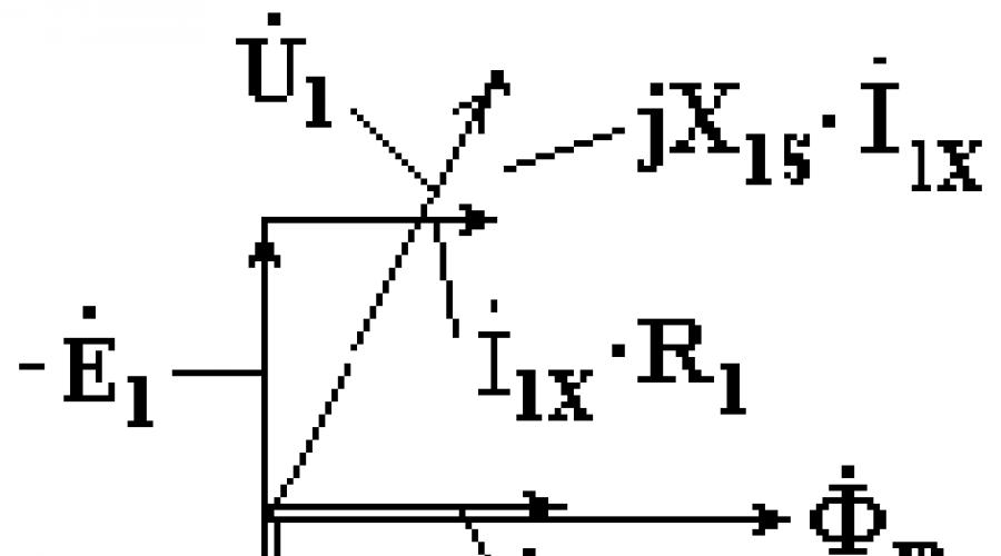
On fig. 10.4 shows a vector diagram of a transformer operating in idle mode.
Transformer EMF vectors and lag behind the main magnetic flux vector by 90°. The voltage vector is parallel to the current vector and the vector leads the current vector by 90°. The voltage vector at the terminals of the primary winding of the transformer is equal to the geometric sum of the vectors - , , Fig. 10.4.

On fig. 10.5 shows the equivalent circuit of a transformer corresponding to equation (10.2).
XE - inductive resistance proportional to the reactive power spent on the creation of the main magnetic flux.
In idle mode.
Transformation ratio ![]() .
.
The transformation ratio is experimentally determined from the experience of idling.
Transformer operation under load
If the voltage U1 is connected to the primary winding of the transformer, and the secondary winding is connected to the load, currents I1 and I2 will appear in the windings. These currents will create magnetic fluxes F1 and F2 directed towards each other. The total magnetic flux in the magnetic circuit decreases. As a result, the EMF E1 and E2 induced by the total flow decrease. The effective value of the voltage U1 remains unchanged. A decrease in E1, according to (10.2), causes an increase in the current I1. With an increase in current I1, the flux F1 increases just enough to compensate for the demagnetizing effect of the flux F2. Equilibrium is restored again at practically the same value of the total flow.
In a loaded transformer, in addition to the main magnetic flux, there are leakage fluxes F1S and F2S, partially closed in air. These flows are induced in the primary and secondary windings of the stray EMF.
where X2S is the leakage inductance of the secondary winding.
For the primary winding, we can write the equation
For secondary winding
where R2 is the active resistance of the secondary winding;
ZН - load resistance.
The main magnetic flux of the transformer is the result of the combined action of the magnetomotive forces of the primary and secondary windings.
Transformer EMF E1, proportional to the main magnetic flux, is approximately equal to the voltage on the primary coil U1. The effective value of the voltage is constant. Therefore, the main magnetic flux of the transformer remains unchanged when the load resistance changes from zero to infinity.
If , then the sum of the magnetomotive forces of the transformer
Equation (10.5) is called the equation of equilibrium of magnetomotive forces.
Equations (10.3), (10.4), (10.5) are called basic transformer equations.
Let's take a coil with a ferromagnetic core and take out the ohmic resistance of the winding as a separate element as shown in Fig. 2.8.
Figure 2.8 - To the derivation of the transformer EMF formula
When an alternating voltage e c is turned on in the coil, according to the law of electromagnetic induction, an EMF of self-induction e L arises.
![]() (2.8)
(2.8)
where ψ is the flux linkage,
W is the number of turns in the winding,
Ф is the main magnetic flux.
We neglect the scattering flux. The voltage applied to the coil and the induced EMF are balanced. According to the second Kirchhoff law for the input circuit, we can write:
e c + e L = i * R exchange, (2.9)
where R obm is the active resistance of the winding.
Since e L >> i * R exchange, we neglect the voltage drop across the ohmic resistance, then e c ≈ – . If the mains voltage is harmonic е с = E m cos ωt, then E m cos ωt = , whence ![]() . Let's find the magnetic flux. To do this, we take the indefinite integral of the right and left sides. We get
. Let's find the magnetic flux. To do this, we take the indefinite integral of the right and left sides. We get
![]() , (2.10)
, (2.10)
but since we consider the magnetic circuit to be linear, only harmonic current flows in the circuit and there is no permanent magnet or constant component, then the integration constant c \u003d 0. Then the fraction in front of the harmonic factor is the amplitude of the magnetic flux, from which we express E m \u003d Ф m * W * ω. Its effective value is
Or we get
where s is the cross section of the magnetic circuit (core, steel).
Expression (2.11) is called the basic formula of the transformer EMF, which is valid only for harmonic voltage. Usually it is modified and the so-called shape factor is introduced, equal to the ratio of the effective value to the average:
 . (2.12)
Let's find it for a harmonic signal, but we find the average value on the interval

Then the form factor is ![]() and the basic formula of the transformer EMF takes the final form:
and the basic formula of the transformer EMF takes the final form:
![]() (2.13)
(2.13)
If the signal is a meander, then the amplitude, effective and average values for half the period are equal to each other and its. You can find the form factor for other signals. The basic formula for transformer EMF will be valid.
Let's build a vector diagram of a coil with a ferromagnetic core. With a sinusoidal voltage at the coil terminals, its magnetic flux is also sinusoidal and lags behind the voltage in phase by an angle π / 2, as shown in Fig. 2.9a.

Figure 2.9 - Vector diagram of a coil with a ferromagnetic
core a) no loss; b) with losses
In a lossless coil, the magnetizing current - reactive current (I p) coincides in phase with the magnetic flux Ф m. If there are losses in the core (), then the angle is the angle of losses for remagnetization of the core. The active component of the current I a characterizes the losses in the magnetic circuit.
LR 5. Study of operating modes of a single-phase transformer
Name the main structural elements of a single-phase transformer.
A single-phase transformer consists of a magnetic circuit (core) and two windings laid on it. The winding connected to the network is called primary, and the winding to which the power receiver is connected is called secondary. The magnetic circuit is made of a ferromagnetic material and serves to amplify the magnetic field and the magnetic flux is closed along it.
Features of the execution of the magnetic circuit of the transformer.
The magnetic circuit of the transformer is in a magnetic field alternating current, and, therefore, in the process of operation, its continuous magnetization reversal occurs and eddy currents are induced in it, for which energy is expended, which goes to heat the magnetic circuit. To reduce energy losses for magnetization reversal, the magnetic circuit is made of a magnetically soft ferromagnet, which has a low residual induction and is easily remagnetized, and to reduce eddy currents, and, consequently, the degree of heating of the magnetic circuit, the magnetic circuit is recruited from separate plates of electrical steel isolated relative to each other.
3. How are determined EMF of windings transformer, what do they depend on?
The EMF of the transformer windings is determined by the formulas: E 1 \u003d 4.44 * Fm * f * N 1 And E 2 \u003d 4.44 * Fm * f * N 2
Where fm- the maximum value of the magnetic flux,
f- AC frequency,
N 1 And N 2- respectively, the number of turns of the primary and secondary windings.
Thus, the EMF of the transformer windings depends on the magnetic flux, the frequency of the alternating current and the number of turns of the windings, and the ratio between the EMF depends on the ratio of the number of turns of the windings.
4. Name the types of energy losses in a transformer, what do they depend on?
During the operation of the transformer, two types of energy losses occur in it:
1. Magnetic losses are energy losses that occur in the magnetic circuit. These losses are proportional to the mains voltage. The energy in this case is expended on the remagnetization of the magnetic circuit and on the creation of eddy currents and is converted into thermal energy released in the magnetic circuit.
2. Electrical losses are the energy losses that occur in the transformer windings. These losses are caused by currents flowing in the windings, and are determined: Re \u003d I 2 1 R 1 + I 2 2 R 2.
That. electrical losses are proportional to the squares of the currents flowing in the transformer windings. In this case, energy is spent on heating the windings.
5. How are magnetic losses in a transformer determined, what do they depend on?
To determine the magnetic losses in the transformer, an experiment XX is carried out, in which the current in the secondary winding is zero, and in the primary winding the current does not exceed 10% of I nom. Because when carrying out this experiment, the electrical receiver is turned off, then all the power measured by the wattmeter included in the circuit of the primary winding of the transformer is the power of electrical and magnetic losses. Magnetic losses are proportional to the voltage applied to the primary winding. Because during the experiment XX, the primary winding is supplied U nom , then the magnetic losses will be the same as in the nominal mode. Electrical losses depend on the currents in the windings, and since the current in the secondary winding is zero, and in the primary winding the current does not exceed 10% of the rated current, and the electrical losses are negligible. Thus, neglecting minor electrical losses, we believe that the entire power measured during the XX experiment is the power of magnetic losses.
6. How are electrical losses in a transformer determined, what do they depend on?
To determine the electrical losses in the transformer, a short circuit test is carried out. To do this, it is necessary to reduce the voltage on the secondary winding to zero, close the secondary clamps to each other and increase the voltage until the rated currents are established in the windings. The voltage at which the rated currents are set in the windings is called the short circuit voltage. As a rule, the short circuit voltage is insignificant and does not exceed 10% of the nominal voltage.
Electrical losses in the transformer during the short circuit experience will be determined :Re= I 2 1nom R 1 + I 2 2nom R 2.
Because when conducting a short circuit test in the transformer windings, rated currents are set, then the electrical losses in them will be the same as in the rated mode. Magnetic losses are proportional to the voltage on the primary winding, and since In the short circuit experiment, an insignificant voltage is applied to the primary winding, then the magnetic losses are insignificant. Thus, neglecting minor magnetic losses, we can assume that the entire power measured in the short circuit test is the power of electrical losses.
E1=4,44fw1Фm.....U1= -E1+r1*I1+X1*I1...
U1 is the voltage complex on the primary winding;
E1 - EMF complex of the primary winding;
I1 is the current complex of the primary winding;
r1 is the resistive resistance of the primary winding;
X1 is the leakage inductive reactance of the primary winding.
EMF induced in the primary winding of the transformer, voltage equations for the primary winding of the transformer.
E1=4.44fw2Фm.....U1= E2+r2*I2+X2*I2...
U2 - voltage complex on the secondary winding;
E2 - EMF complex of the secondary winding;
I2 - current complex of the secondary winding;
r2 is the resistive resistance of the secondary winding;
X2 - leakage inductive reactance of the secondary winding.
6. Experience of idling, parameters determined during the experiment. The idling experience (Fig. 11.4, a) is used to determine the transformation ratio. In this case, the low voltage winding is connected to a device (potential - regulator), which allows changing the voltage supplied to the transformer over a wide range, and the winding higher voltage open. In order to determine the transformation ratio, it is sufficient to supply a voltage of 0.1 UH for low power transformers and (0.33 ... 0.5) UH for high power transformers to the low voltage winding. The voltage drop in the primary winding is very small. With acceptable accuracy, we can assume that E1 \u003d U1 and E2 \u003d U2, since the current in the secondary winding is practically zero. From the experience of idling the transformer, the dependences of the idling current Ix, power consumption Px and power factor cosφ on the value of the input voltage U1 are also determined, with the secondary winding open, that is, at I2 = 0. Idle current power transformers ranges from 10 (for low-power transformers) to 2% (for high-power transformers) of the nominal value. When taking the characteristics of idling, the input voltage is changed in the range from 0.6 to 1.2 UH in such a way as to obtain 6 ... 7 readings. Figure 11.4.6 shows an approximate view of the idling characteristics. The no-load power characterizes the electrical energy consumed in the transformer itself, since no energy is consumed from the secondary winding. The energy in the transformer is spent on heating the windings by the current passing through them and heating the core steel (eddy currents and hysteresis). The heating losses of the windings (losses in the windings) during idling are negligible. In practice, we can assume that all idle losses are concentrated in the steel of the core and go to heat it.
7.Experience short circuit transformer, ODA parameters during the experiment. The short circuit test is carried out according to the scheme shown in Figure 11.5, a. A voltage is applied to the low voltage winding, at which a current flows in the short-circuited high voltage winding. rated current. This voltage is called the short-circuit voltage ek%; its value is given in the transformer passport as a percentage of the nominal. Since in this experiment, due to the low voltage supplied to the low voltage winding, the magnetic flux in the core is very small and the core does not heat up, it is believed that all the power consumed by the transformer during the short circuit test is spent on electrical losses in the winding conductors. The short-circuit characteristics (Fig. 11.5,6) are the dependences of the consumed current Ik, power Pk and power factor cosφ, on the applied voltage with the secondary winding closed.
10. Schemes for connecting the windings of 3-phase transformers. utilization rate. The windings of three-phase transformers are connected in star (Y) or delta (D). Usually, the primary windings are connected to a star, and the secondary windings are connected to a triangle, or both windings are connected to a star. A three-phase transformer has two three-phase windings - high (HV) and low (LV) voltage, each of which includes three phase windings, or phase. Thus, a three-phase transformer has six independent phase windings and 12 outputs with corresponding clamps, and the initial outputs of the phases of the higher voltage winding are denoted by the letters A, B, C, the final outputs are X, Y, Z, and for similar outputs of the phases of the low voltage winding, such designations: a, b, c, x, y, z ...... In most cases, the windings of three-phase transformers are connected either in a star -Y or in a triangle - Δ ... Phase factor transformations of a three-phase transformer are found as the ratio of phase voltages at idle: nf = Ufinh / Ufnh.... linear transformation ratio, depending on the phase transformation ratio and the type of connection of the phase windings of the higher and low voltage transformer, according to the formula: nl \u003d Ulvnh / Ulnh.
11. Groups for connecting windings of 3-phase transformers. for what purpose is determined. The group of connections of the transformer windings characterizes the mutual orientation of the voltages of the primary and secondary windings
12. Conditions for switching on transformers for parallel operation. provided that none of the windings is loaded with a current exceeding the allowable current for this winding ..... Parallel operation of transformers is allowed under the following conditions: the winding connection groups are the same, the power ratio of the transformers is not more than 1:3, the transformation ratios do not differ by more than ±0.5%, short-circuit voltages differ by no more than ±10%, transformers are phased.
14. Autotransformer. The main difference between an autotransformer and a conventional transformer is that its two windings necessarily have electrical connection, they are wound on one rod, power is transferred between the windings in a combined way - by electromagnetic induction and electrical connection. This reduces the size and cost of the machine.
15. The principle of operation of an asynchronous motor. The device of the stator of an asynchronous machine. applied to the stator winding AC voltage, under the action of which a current flows through these windings and creates a rotating magnetic field. The magnetic field acts on the rotor winding and, according to the law of electromagnetic induction, induces an EMF in them. In the rotor winding, under the action of the induced EMF, a current arises. The current in the rotor winding creates its own magnetic field, which interacts with the rotating magnetic field of the stator. As a result, a force acts on each tooth of the rotor magnetic circuit, which, adding up around the circumference, creates a rotating electromagnetic moment that causes the rotor to rotate............ The stationary part of the machine is called the stator. The stator core is recruited from sheet electrical steel and pressed into the frame. On the inner surface of the sheets from which the stator core is made, there are grooves into which a three-phase winding (3) is laid. The stator winding is made mainly from insulated copper wire round or rectangular section, less often - from aluminum.
16. The device of an asynchronous machine with a short circuit. rotor, the design of the main assembly units. consists of copper or aluminum rods, short-circuited at the ends with two rings. The rods of this winding are inserted into the grooves of the rotor core. Rotor and stator cores have a gear structure. In machines of small and medium power, the winding is usually made by pouring molten aluminum alloy into the grooves of the rotor core.
17 .The device of an asynchronous machine with a phase rotor, the design of the main assembly units. The phase rotor has a three-phase (in the general case, a multi-phase) winding, usually connected according to the “star” scheme and brought out to slip rings that rotate with the machine shaft. With the help of graphite or metal-graphite brushes sliding along these rings, into the rotor winding circuit: include ballast rheostat, acting as an additional active resistance, the same for each phase. By reducing the starting current, the starting torque is increased to the maximum value (at the first moment of time). Such motors are used to drive mechanisms that are launched under heavy load or require smooth speed control. include inductances (chokes) in each phase of the rotor. The resistance of the chokes depends on the frequency of the flowing current, and, as you know, in the rotor at the first moment of start-up, the frequency of slip currents is the highest. As the rotor spins up, the frequency of the induced currents decreases, and with it the inductor resistance decreases. The inductive resistance in the phase rotor circuit allows you to automate the procedure for starting the engine, and, if necessary, to “catch” the engine, whose speed has dropped due to overload. The inductance keeps the rotor currents at a constant level. include source direct current , thus obtaining a synchronous machine. turn on inverter power, which allows you to control the speed and torque characteristics of the engine. This is a special mode of operation (double-feed machine). It is possible to turn on the mains voltage without an inverter, with a phasing opposite to that with which the stator is powered.
18. Analogy between an asynchronous machine and a transformer. EMF induced in the stator windings in xx mode. In a synchronous motor the role of the secondary winding of the transformer is played by the rotor winding, and the stator is the primary winding ..... It is necessary here, however, to pay attention to the following significant difference between the induction motor and the transformer ..... As you know, the transformer has both windings - primary and secondary, stationary, while in an asynchronous motor we have only a primary (stator) winding fixed, while the secondary (rotary) winding of an induction motor is movable; due to this, the frequency of the currents flowing in the secondary circuit (rotor) of an induction motor is a variable, which, as you know, is not observed in transformers.
20. Losses and efficiency of an induction motor.P The mothers are divided into mechanical, magnetic and electrical. Mechanical losses in an induction motor are caused by friction in the bearings and friction of the rotating parts against the air. Additional losses are caused by the presence of stray fields in the motor and field pulsation in the teeth of the rotor and stator. Efficiency of an asynchronous motor η = Р2/Р1 = 1 - ∑р/ Р1.
21. The principle of operation of a 3-phase asynchronous motor. When connected to the network, a circular rotating magnetic field arises in the stator, which penetrates the short-circuited rotor winding and induces an induction current in it. From here, following Ampère's law (emf acts on a current-carrying conductor placed in a magnetic field), the rotor begins to rotate. The rotor speed depends on the frequency of the supply voltage and on the number of pairs of magnetic poles. The difference between the frequency of rotation of the stator magnetic field and the frequency of rotation of the rotor is characterized by slip. The motor is called asynchronous because the frequency of rotation of the magnetic field of the stator does not coincide with the frequency of rotation of the rotor. The synchronous motor has a difference in the design of the rotor. The rotor is either a permanent magnet or an electromagnet, or it has a part of a squirrel cage (for starting) and permanent or electromagnets. In a synchronous motor, the rotational speed of the stator magnetic field and the rotational speed of the rotor are the same. To start, use auxiliary asynchronous electric motors, or a rotor with a squirrel-cage winding.
Similar information.
WORKSHOP
FOR ELECTRIC MACHINES
AND DEVICES
For full-time and part-time students
in the field of instrument making and optotechnics
as a teaching aid for students of higher education
institutions studying in the specialty 200101 (190100)
"Instrument making"
Kazan 2005
UDC 621.375+621.316.5
BBC 31.261+31.264
Prokhorov S.G., Khusnutdinov R.A. Workshop on electric machines
and devices: Textbook: For full-time and part-time students. Kazan: Kazan Publishing House. state tech. un-ta, 2005. 90 p.
ISBN 5-7579-0806-8
Designed for holding practical exercises and implementation independent work in the discipline "Electrical Machines and Apparatus" in the direction of training a certified specialist 653700 - "Instrument Engineering".
The manual may be useful for students studying disciplines
"Electrical engineering", "Electromechanical equipment in instrument making",
"Electrical machines in instrumentation", as well as students of all
engineering specialties, including the electrical profile.
Tab. Il. Bibliography: 11 titles.
Reviewers: Department of Electric Drive and Automation of Industrial Installations and Technological Complexes (Kazan State Power Engineering University); professor, cand. Phys.-Math. Sciences, Associate Professor V.A. Kirsanov (Kazan branch of the Chelyabinsk Tank Institute)
ISBN 5-7579-0806-8 © Kazan Publishing House. state tech. university, 2005
© Prokhorov S.G., Khusnutdinov R.A.,
The proposed tests in the discipline "Electrical Machines and Apparatus" are intended for practical training and independent work. The tests are compiled in the sections "Transformers", "Asynchronous machines", " Synchronous machines”, “DC collector machines”, “ Electrical apparatus". Answers in the form of a table are given at the end of the manual.
TRANSFORMERS
1. Why are air gaps in a transformer kept to a minimum?
1) To increase the mechanical strength of the core.
3) To reduce the magnetic noise of the transformer.
4) To increase the mass of the core.
2. Why is the transformer core made of electrical steel?
1) To reduce the no-load current.
2) To reduce the magnetizing component of the no-load current
3) To reduce the active component of the no-load current.
4) To improve corrosion resistance.
3. Why are the core plates of the transformer pulled together with studs?
1) To increase mechanical strength.
2) For attaching the transformer to the object.
3) To reduce moisture inside the core.
4) To reduce magnetic noise.
4. Why is the transformer core made of electrically insulated plates of electrical steel?
1) To reduce the mass of the core.
2) To increase the electrical strength of the core.
3) To reduce eddy currents.
4) To simplify the design of the transformer.
5. How are the beginnings of the primary winding of a three-phase transformer indicated?
1) a, b, c 2) x, y, z 3) A, B, C 4) X, Y, Z
6. How are the primary and secondary windings of a three-phase transformer connected if the transformer has 11 groups (Y - star, Δ - triangle)?
1) Y/Δ 2) Δ/Y 3) Y/Y 4) Δ/Δ
7. How do the magnetic core and the winding of a conventional transformer differ in mass from an autotransformer if the transformation ratios are the same TO=1.95? The power and rated voltages of the devices are the same.
1) Do not differ.
2) The masses of the magnetic circuit and the winding of the autotransformer are less than the masses
magnetic circuit and windings of a conventional transformer, respectively.
3) The mass of the magnetic circuit of an autotransformer is less than the mass of the magnetic circuit of a conventional transformer, and the masses of the windings are equal.
4) The masses of the magnetic circuit and windings of a conventional transformer are less than those of the corresponding values of an autotransformer.
5) The mass of the winding of an autotransformer is less than the mass of the windings of a conventional transformer, and the masses of the magnetic circuits are equal.
8. On what law of electrical engineering is the principle of operation of a transformer based?
1) On the law of electromagnetic forces.
2) On Ohm's law.
3) On the law of electromagnetic induction.
4) On the first law of Kirchhoff.
5) On the second law of Kirchhoff.
9. What will happen to the transformer if it is connected to a DC voltage network of the same magnitude?
1) Nothing will happen.
2) May burn out.
3) The main magnetic flux will decrease.
4) The leakage magnetic flux of the primary winding will decrease.
10. What does a transformer convert?
1) The magnitude of the current.
2) The magnitude of the voltage.
3) Frequency.
4) Current and voltage values.
11. How is electrical energy transferred from the primary winding of an autotransformer to the secondary?
1) Electrically.
2) Electromagnetically.
3) Electrical and electromagnetic way.
4) As in a conventional transformer.
12. What magnetic flux in a transformer is a carrier of electrical energy?
1) Magnetic leakage flux of the primary winding.
2) Magnetic leakage flux of the secondary winding.
3) The magnetic flux of the secondary winding.
4) Magnetic flux of the core.
13. What influences the EMF of self-induction of the primary winding of the transformer?
1) Increases the active resistance of the primary winding.
2) Reduces the active resistance of the primary winding.
3) Reduces the current of the primary winding of the transformer.
4) Increases the current of the secondary winding of the transformer.
5) Increases the current of the primary winding of the transformer.
14. What influences the EMF of self-induction of the secondary winding of the transformer?
1) Increases the active resistance of the secondary winding.
2) Reduces the active resistance of the secondary winding.
3) Reduces the current of the secondary winding of the transformer.
4) Increases the current of the primary winding of the transformer.
5) Reduces the inductive resistance of the secondary winding
transformer.
15. What is the role of the EMF of the mutual inductance of the secondary winding of the transformer?
1) Is the source of EMF for the secondary circuit.
2) Reduces the primary current.
3) Reduces the secondary current.
4) Increases the magnetic flux of the transformer.
16. Choose the formula for the law of electromagnetic induction:
Choose the correct spelling of the effective value of the EMF of the secondary winding of the transformer.
18. How are the magnitudes of the short circuit voltage U 1k and nominal U 1n in medium power transformers?
1) U 1k ≈ 0.05. U 1n 2) U 1k ≈ 0.5. U 1n 3) U 1k ≈ 0.6. U 1n
4) U 1k ≈ 0.75. U 1n 5) U 1k ≈ U 1n
19. What parameters of the T-shaped equivalent circuit of the transformer are determined from the experience of idling?
1) r 0 , r 1 2) X 0 , r 1 3) r' 2 , X' 2