Knowledge of switching equipment principles of building a LAN. Coursework: Designing a local area network Creating a local
Read also
Large companies have in circulation a large amount of data of a different nature:
- text files;
- graphic;
- Images;
- tables;
- scheme.
For management, it is important that all information has a convenient format, is easily converted and transmitted on any medium to the right hands. But paper documents have long begun to be replaced by digitized ones, since a computer can contain a lot of data that is much more convenient to work with using process automation. This is also facilitated by the transfer of information, reports and contracts to partners or inspection companies without long journeys.
So there was a need for the widespread supply of departments of firms with electronic computing devices. Along with this, the question arose of combining these devices into a single complex for the protection, safety and convenience of moving files.
In this article, we will tell you how to facilitate the design of a local computer (computer) network in an enterprise.
What is a LAN, its functions
This is a connecting connection of a number of computers in one closed space. Often this method is used in large companies, in production. You can also independently create a small connection of 2 - 3 devices, even at home. The more inclusions in the structure, the more complex it becomes.
Types of networking
There are two types of connection, they differ in complexity and the presence of a leading, central link:
- Equal.
- Multilevel.
Equivalent, they are peer-to-peer, are characterized by similarity in technical characteristics. They have the same distribution of functions - each user can access all common documents, perform the same operations. Such a scheme is easy to manage, it does not require multiple efforts to create it. The downside is its limitedness - no more than 10 members can join this circle, otherwise the overall efficiency of work and speed are violated.
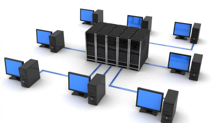
Server design of a company's local network is more laborious, however, such a system has a higher level of information protection, and there is also a clear distribution of responsibilities within the web. The best in terms of technical characteristics (powerful, reliable, with more RAM) computer is assigned as a server. This is the center of the entire LAN, all data is stored here, from the same point you can open or stop access to documents to other users.
Functions of computer networks
The main properties to consider when drafting a project:
- Ability to connect additional devices. Initially, there may be several machines in the grid, with the expansion of the company, additional inclusion may be required. When calculating the power, you should pay attention to this, otherwise you will need to redevelop and buy new ones. Consumables increased strength.
- Adaptation for different technologies. It is necessary to ensure the flexibility of the system and its adaptability to different network cables and different software.
- Availability of redundant lines. First, it refers to the exit points of ordinary computers. In case of failure, it should be possible to connect another cord. Secondly, you need to ensure the uninterrupted operation of the server with a multi-level connection. You can do this by ensuring automatic failover to the second hub.
- Reliability. Equipped with uninterruptible power supplies, autonomous energy reserves to minimize the possibility of communication interruption.
- Protection from outside influences and hacking. Stored data can be protected not just with a password, but with a whole bunch of devices: a hub, a switch, a router, and a remote access server.
- Automated and manual control. It is important to install a program that will analyze the state of the grid at every moment of time and notify you of malfunctions so that they can be quickly eliminated. An example of such software is RMON. At the same time, personal monitoring via Internet servers can also be used.

Drawing up technical requirements for the design and calculation of a local area network (LAN) in an enterprise
From the properties come the conditions that must be taken into account when drawing up a project. The entire design process begins with the preparation of technical specifications (TOR). It contains:
- Data security standards.
- Providing all connected computers with access to information.
- Performance parameters: response time from a user request to opening the desired page, throughput, that is, the amount of data in operation and transmission delay.
- Reliability conditions, that is, readiness for long-term, even permanent work without interruption.
- Replacement of components - expansion of the grid, additional inclusions or installation of equipment of a different power.
- Support for different types of traffic: text, graphics, multimedia content.
- Providing centralized and remote control.
- Integration of various systems and software packages.
When the TOR is compiled in accordance with the needs of users, the type of inclusion of all points in one network is selected.
Basic LAN topologies
These are ways to physically connect devices. The most frequent are represented by three figures:
- tire;
- ring;
- star.
Busbar (linear)
When assembling, one lead cable is used; wires to user computers already depart from it. The main cord is directly connected to the server that stores the information. It also selects and filters data, provides or restricts access.

Advantages:
- Disabling or problems with one element does not break the rest of the grid.
- Designing an organization's LAN is fairly simple.
- Relatively low cost of installation and consumables.
Flaws:
- A failure or damage to the carrier cable brings the entire system to a halt.
- A small area can be connected in this way.
- Performance can suffer from this, especially if the connection passes between more than 10 devices.
"Ring" (ring)
All user computers are connected in series - from one device to another. This is often done in the case of peer-to-peer LANs. In general, this technology is used less and less.

Advantages:
- No hub, router or other network equipment costs.
- Multiple users can send information at once.
Flaws:
- The transfer rate in the whole mesh depends on the power of the slowest processor.
- If there is a problem in the cable or if any element is not connected, the general work stops.
- Setting up such a system is quite difficult.
- When connecting an additional workplace, it is necessary to interrupt the general activity.
"Star"
This is a parallel connection of devices to the network to a common source - the server. As a cent, a hub or concentrator is most often used. All data is transmitted through it. In this way, not only computers can work, but also printers, fax machines and other equipment. In modern enterprises, this is the most frequently used method of organizing activities.

Advantages:
- It is easy to connect another place.
- Performance does not depend on the speed of individual elements, so it remains at a stable high level.
- Just find the break.
Flaws:
- A malfunction of the central unit terminates the activity of all users.
- The number of connections is determined by the number of ports on the server device.
- The network consumes a lot of cable.
- Expensive equipment.
Stages of LAN software design
This is a multi-stage process that requires the competent participation of many specialists, since it is necessary to pre-calculate the required cable throughput, take into account the configuration of the premises, install and configure the equipment.
Organization space planning
The offices of workers and superiors should be arranged in accordance with the chosen topology. If the star shape suits you, then you should place the main technique in the room that is the main one and is located in the center. It could also be the management's office. In the case of bus distribution, the service may be located in the most remote room along the corridor.
Building a local network diagram

The drawing can be made in specialized computer-aided design programs. ZVSOFT products are ideal - they contain all the basic elements that will be required during construction.
The network should take into account:
- maximum voltage;
- sequence of occurrences;
- possible interruptions;
- cost-effectiveness of the installation;
- convenient power supply.
The characteristics of the LAN must be selected in accordance with the layout of the premises of the organization and the equipment used.
Computer and network device settings
When choosing and purchasing mesh elements, it is important to consider the following factors:
- Compatibility with different programs and new technologies.
- Data transfer rate and device performance.
- The quantity and quality of cables depends on the chosen topology.
- Method of managing exchanges in the network.
- Protection against interference and failures by winding wires.
- The cost and power of network adapters, transceivers, repeaters, hubs, switches.
Principles of designing a LAN using computer programs
When drawing up a project, it is important to take into account a large number of nuances. This will help software from ZWSOFT. The company develops and sells multifunctional software to automate the work of design engineers. Basic CAD is similar to the popular but expensive package from Autodesk - AutoCAD, but surpasses it in ease and convenience of licensing, as well as in a more loyal pricing policy.

Benefits of the program:
- intuitive, user-friendly interface in black.
- Wide selection of tools.
- Work in two-dimensional and three-dimensional space.
- 3D visualization.
- Integration with most popular file extensions.
- Organization of LAN elements in the form of blocks.
- Counting the lengths of cable lines.
- Visual arrangement of elements and nodes.
- Simultaneous work with graphics and text data.
- Ability to install additional applications.
For ZWCAD - a module that extends the functions of the basic CAD in the field of multimedia circuit design. All drawings are made with automated calculation of local cables computer network and their labeling.
Advantages:
- automation of selection of switching systems;
- wide library of elements;
- parallel filling of the cable magazine;
- automatic creation of specifications;
- adding equipment to the library;
- simultaneous work of several users with the database;
- schematic marks for the location of devices and pieces of furniture.
It will help to make a project in a three-dimensional form, create it in 3D. Intelligent tools allow you to quickly lay LAN routes to connection points, visualize the places where cables pass, organize line intersections, make cuts of connected equipment and technological furniture (including in dynamic mode). Using the component editor, you can create a library like cabinets, switching devices, cables, clamps, etc., as well as assign characteristics to them, on the basis of which it is possible to draw up specifications and calculations in the future. Thus, the functions of this software will help complete the master plan of the premises of the organization with the tracing of all LAN lines.
Create a local area network project in your enterprise together with programs from ZVSOFT.
In the modern world, local networks have become not just necessary - they are actually necessary to achieve good level labor productivity. However, before you start using such a network, you should create and configure it. Both of these processes are quite difficult and require maximum concentration, especially the first of them. A poorly designed and configured LAN will not work at all, or it will not function at all as it should, so creating a local network should be the focus of the person doing it.
What is a local network
As a rule, the creation of such communication systems is caused by the need to share data by users who work on remote computers. A LAN not only enables near-instantaneous exchange of information and simultaneous file sharing, but also allows remote use of network printers and other devices.
A local network is a complete set of software and hardware resources aimed at creating a single information space. In fact, this is a number of computers located at a distance from each other and connected by a communication line - a cable. The main difference between a LAN and other types of networks is short distance where the workstations are located.
Pre-project preparation and design
Before you create a local network, you must first design it, that is, plan the process of its creation. This stage is one of the most significant, since the LAN includes a huge number of components and nodes.
Initially, the terms of reference are drawn up on the basis of primary data, defining several points:
- Functions and tasks of the LAN.
- Selected topology.
- List of available equipment.
Once you have these points in mind, you can start designing. The project itself should contain LAN schemes, network equipment placement points, a list of required software and hardware.

A local area network is a complex mechanism, but if it is designed correctly and the equipment is selected in accordance with the requirements, then the likelihood of problems in the operation of the communication mechanism becomes minimal.
Required Hardware
There is a list of equipment without which no LAN can function. It includes:
- Data lines. The most commonly used coaxial cable and optical fiber. In this case, the length of the coaxial cannot exceed several hundred meters, however, if it is necessary to extend the network over long distances, special repeaters are used - signal repeaters that do not allow it to fade.
- Communication equipment: network cards (devices that perform duplex exchange of information between a computer and a data transmission medium), hubs (they break the network into separate segments, structuring the network physically), routers (take on the choice of the packet transmission route), switches (logically divide the LAN into segments, combining several physical circuits), repeaters (provide signal recovery, allowing you to increase the length of the transmission medium), transceivers (amplify the signal and convert it to other forms, allowing you to use different data transmission media).
List of software
No LAN is complete without software. Required Programs for local network include:
- Operating systems of work nodes. The most commonly used operating system remains Windows 7, although Windows XP is also not losing ground.
- Network operating systems installed on servers are the basis of the LAN, since it is impossible to set up a local network without them. Exactly these software take control of all data flows between the main and secondary nodes, providing the possibility of collective access to network resources. As a rule, the operating systems of Microsoft Corporation are used: Windows Server 2003 or 2008.

- Network services and applications that enable users to access deleted files, print documents on a network printer, view networked work nodes, and send electronic messages. The implementation of such services is carried out using software.
Creation and installation of a LAN
Installation and commissioning work takes the most time, since it is necessary to create a local network in several stages:
- Before starting the installation of communication lines and switching devices, you must first prepare the room.
- Next, you can lay the cable, as well as install the necessary equipment.
- Devices of the server and workstations should be connected to the cable communication line.
- After that, the software is installed and configured.
Installation of cable and equipment has a number of features, therefore, if there are difficulties with how to connect a local network, it is better to entrust this issue to specialists.
Joining two computers in a LAN
In some cases, it may be necessary to combine two computers into one network, for example, to create a common information space. This is not very difficult to do if you follow a certain algorithm of actions:
- If necessary, install network adapters in both computers, not forgetting the drivers.

- Purchase a crimped network cable for connection. If you have the necessary knowledge and skills, crimping can be done on your own - the local network of two computers will not become worse quality from this.
- Connect both workstations with a communication line.
- Set up the LAN in a specific order.
Algorithm for setting up a local network between two computers for Windows 7
- Select the Start menu, then press right click mouse on the "Computer" icon, enter the "Properties" submenu.
- You need to find in the list "Computer name and domain", and then select the item with the change in settings.
- The working name of the computer must be changed by clicking on the appropriate icons.
- The group name should remain unchanged - "Workgroup", but the computer names are changed to "pc1" and "pc2" for the first and second subscriber, respectively.
- You can now click OK and restart your computer.

In most cases, you may want to give each host a unique IP address:
- From the Start menu, select Settings and then Network Connections.
- Right-click to open the "Properties" submenu next to the "Local Area Connection" icon.
- In the "General" tab, select "Properties" of the item "Internet Protocol".
- Make the line "Use the following IP address" active and enter the value 192.168.0.100. After that, save the changes made.
Local network and internet
Work nodes connected in a LAN can be connected to the Internet. A local network, to which the Internet can be connected in two ways, will work at a speed divided in two.
The first way to connect is to use a router, which is assigned an identifying IP address. And in the second case, you can use a wireless connection.
In this case, the local network is the interaction of two computers, master and slave, so the IP address is written in the gateway of the main one, previously connected to the worldwide network.

If the LAN is based on the use of a server, each workstation must have an individual IP address, and a proxy server is specified in the browser settings through which the Internet is accessed.
Wireless LAN
A wireless local area network is a type of LAN that uses high-frequency radio waves to transmit information. WLAN is an excellent alternative to the conventional cable communication system, having a number of advantages:
- Improving labor productivity. WLAN makes it possible to use the Internet without being tied to one room. You can freely change your location without losing your internet connection.
- Easy installation and configuration, financial savings and reliability - all these factors are due to the absence of a cable communication line.
- Flexibility. Installing a wireless network is real where there is no way to stretch the cable.
- Possibility of expansion. Network scalability is greatly simplified with wireless network adapters that can be installed on any work node.
WLAN has a certain range, which depends on the characteristics of the network devices and the noise immunity of the building. As a rule, the range of radio waves reaches 160 m.
Necessary equipment for creating a wireless LAN
An access point is used to connect other workstations to the network. This device is equipped with a special antenna that controls duplex data transmission (sending and transmitting) using radio signals. Such a point can transmit a signal at a distance of up to 100 m indoors and up to 50 km in an open area.

Access points significantly expand the computing power of the entire communication system, allowing users to freely move between each of them without losing connection to the LAN or the Internet. In fact, these radio points act as hubs, providing a connection to the network.
Using access points allows you to scale up your entire wireless LAN by simply adding new devices. The number of subscribers that one radio point can withstand generally depends on the network load, since the traffic is divided equally between each of the users.
Wireless LAN: Windows 7 Setup Flow
First prepare the ADSL modem with WiFi technology, as well as client points with wireless adapters connected to them. After that, you can start building a wireless LAN:
- Connect the modem to the electrical network.
- Run the WLAN setup wizard on the client device.
- Select the SSID from the list of found wireless networks.
Access point setup:
- The first step is to configure the TCP/IP protocol properties by specifying the IP address and subnet mask.
- After that, specify the value of the DNS server, since it is not possible to fully configure the local network without this parameter. In most cases, it is enough to make the automatic assignment of the DNS address active.
- It is also mandatory to configure the parameters of the wireless network itself, in which security is important.
- At this stage, you need to configure the Internet connection and filtering for the Windows 7 firewall.
- And lastly, the wires are connected and the WLAN network is tested.
To create an optimal information space, you can combine types of networks - cable and wireless, allowing you to use the advantages of each of them for the benefit of the enterprise. However, it is important to remember that in our time, it is more and more used precisely wireless network WLAN, which has all the advantages of cable networks and is devoid of their disadvantages.
After completing the creation and configuration of the local network, it is important to provide for its administration and the ability to Maintenance. Even if the LAN installation is perfect, during its operation various hardware or software malfunctions are almost inevitable, which is why maintenance should be regular.
Send your good work in the knowledge base is simple. Use the form below
Students, graduate students, young scientists who use the knowledge base in their studies and work will be very grateful to you.
Hosted at http://www.allbest.ru/
1. INTRODUCTION
The purpose of the passage industrial practice in the profile of the specialty was to consolidate, deepen and systematize knowledge based on the activities of the company JSC "RadioZavod" in the direction of "Management in technical systems". During the period of industrial practice, the plan of theoretical and practical training of the student was completed in full.
During the period from July 1 to July 29, I reviewed and studied the following: the principles of building local area networks; structure and operation of the LAN; study of network protocols; basics of administration.
2. LOCAL NETWORKS
2.1 Topologies of local networks
LAN (eng. LAN - Lokal Area Network) is understood as the joint connection of several separate computer workstations (workstations) to a single data transmission channel.
The topology of a computer network is understood as the configuration of a graph, the vertices of which correspond to the computers of the network, and the edges to physical connections between them. Computers connected to a network are often referred to as stations or network nodes. Logical links are data transfer routes between network nodes and are formed by appropriately configuring the communication equipment.
Topology selection electrical connections significantly affects many characteristics of the network. For example, the presence of redundant links increases the reliability of the network and makes it possible to balance the load of individual channels. The ease of adding new nodes, inherent in some topologies, makes the network easily expandable. Economic considerations often lead to the choice of topologies, which are characterized by a minimum total length of communication lines.
A fully connected topology (Figure 2.1, a) corresponds to a network in which each computer on the network is connected to all the others. Despite the logical simplicity, this option turns out to be cumbersome and inefficient. Indeed, each computer on the network must have a large number of communication ports, sufficient to communicate with each of the other computers on the network. For each pair of computers, a separate electrical communication line must be allocated. Fully connected topologies are rarely used.
A mesh topology is obtained from a fully connected topology by removing some possible connections (Figure 2.1, b). In a network with a mesh topology, only those computers between which intensive data exchange takes place are directly connected, and for data exchange between computers that are not connected by direct connections, transit transmissions through intermediate nodes are used.
The common bus (Figure 2.1, c) is a very common topology for local networks. In this case, computers are connected to one coaxial cable. The transmitted information can be distributed in both directions. The use of a common bus reduces the cost of wiring, unifies the connection of various modules, provides the possibility of almost instantaneous broadcast access to all stations on the network. Thus, the main advantages of such a scheme are the low cost and ease of cabling around the premises. The most serious disadvantage of the common bus is its low reliability: any defect in the cable or connectors completely paralyzes the entire network. Another disadvantage of the shared bus is its low performance, since with this connection method, only one computer at a time can transmit data to the network. Therefore, the bandwidth of the communication channel is always divided here between all network nodes.
Star topology (Figure 2.1, d). In this case, each computer is connected by a separate cable to a common device, called a hub, which is located in the center of the network. The function of the hub is to direct the information transmitted by the computer to one or all other computers on the network. The main advantage of this topology is that any problems with the cable only affect the computer to which this cable is connected, and only a malfunction of the hub can disable the entire network. The disadvantages of a star topology include the higher cost of network equipment. In addition, the ability to increase the number of nodes in the network is limited by the number of hub ports. Sometimes it makes sense to build a network using several hubs, hierarchically interconnected by star connections (Figure 2.1, e).
In networks with a ring configuration (Figure 2.1, e), data is transferred around the ring from one computer to another, usually in one direction. If the computer recognizes the data as "its own", then it copies it to itself in the internal buffer. In a network with a ring topology, special measures must be taken so that in the event of a failure or disconnection of a station, the communication channel between the other stations is not interrupted. The ring is a very convenient configuration for organizing feedback - the data, having made a full turn, returns to the source node. Therefore, this node can control the process of delivering data to the destination. Often this property of the ring is used to test network connectivity and find a node that is not working correctly.
Figure 2.1 Typical network topologies
2.2 Communication medium
The communication line (Figure 2.2) generally consists of a physical medium through which electrical information signals are transmitted, data transmission equipment and intermediate equipment.
Figure 2.2 Composition of the communication line
Physical environment data transmission can be a cable, that is, a set of wires, insulating and protective sheaths and connectors, as well as the earth's atmosphere or outer space through which electromagnetic waves propagate. Depending on the data transmission medium, communication lines are divided into:
Wired (overhead) communication lines are wires without any insulating or shielding braids, laid between poles and hanging in the air. Such communication lines traditionally carry telephone or telegraph signals, but in the absence of other possibilities, these lines are also used to transmit computer data.
Cable lines are a rather complex structure. The cable consists of conductors enclosed in several layers of insulation: electrical, electromagnetic, mechanical. In addition, the cable can be equipped with connectors that allow you to quickly connect various equipment to it. There are three main types of cable used in computer networks: twisted-pair cables copper wires, coaxial cables with a copper core, as well as fiber optic cables.
Terrestrial and satellite communications generated by a transmitter and receiver of radio waves. There is a large number various types radio channels other than those used frequency range, and the channel range.
The main characteristics of communication lines include:
amplitude-frequency characteristic;
· bandwidth;
attenuation
· noise immunity;
crosstalk at the near end of the line;
throughput;
Reliability of data transfer;
unit cost.
Factors affecting the physical performance of the network:
1) Serviceability of computers connected to the network.
2) Serviceability of network equipment (adapters, transceivers, connectors, etc.).
3) Network cable integrity.
4) Limitation of the cable length associated with the attenuation of the signal propagating through it.
2.3 Types of local networks
There are several types of computer networks:
global networks,
· Regional networks,
· Urban networks.
According to the speed of information transfer, computer networks are divided into:
low-speed (up to 10 Mbps),
medium-speed (up to 100 Mbps),
high-speed (over 100 Mbps);
The term baud is widely used to define the data transfer rate in a network. Baud is a unit of signal transmission rate, measured as the number of discrete transitions or events per second. If each event is one bit, the baud is equivalent, bps.
From the point of view of organizing the interaction of computers, networks are divided into peer-to-peer (Peer-to-Peer Network) and with a dedicated server (Dedicated Server Network).
peer-to-peer networks. All computers in a peer-to-peer network are equal. Any network user can access data stored on any computer. The advantage of peer-to-peer networks is that there is no need to copy all the files used by several users at once to the server. In principle, any network user has the ability to use all the data stored on other computers on the network and the devices connected to them. The main drawback of the peer-to-peer network is a significant increase in the time for solving applied problems. This is due to the fact that each computer on the network processes all requests coming to it from other users.
In a network with a dedicated server, one of the computers performs the functions of storing data intended for use by all workstations, managing interaction between workstations, and a number of service functions. Interaction between workstations in the network, as a rule, is carried out through the server. The logical organization of such a network can be represented by a star topology. The role of the central device is performed by the server. Advantages of a network with a dedicated server: a reliable information security system; high speed; no restrictions on the number of workstations; Ease of Management. Disadvantages of the network: high cost due to the allocation of one computer for the server; dependence of network speed and reliability on the server; less flexibility compared to a peer-to-peer network.
Modem connection. The most common and well-known method of connecting to the Internet in Russia is a modem connection using a telephone line.
A modem is connected to the computer - a device for receiving and transmitting data, which is connected to a regular telephone line. When a connection needs to be established, the modem dials telephone number, which is answered by another modem installed by the ISP. A connection is established between the modems and data is transmitted.
The main advantage of modem communication is its prevalence and low price. If a high-quality telephone line is available, modem communication is also available - there is no need to organize a special channel. The initial cost of connecting to a dial-up provider is low. However, modem communication also has major drawbacks, a significant part of which are associated with the deplorable state of the bulk of Russian telephone lines. A well-known problem with modem communication is low speed. Theoretically, modern modems are capable of transmitting data at speeds up to 56 Kbps in the direction from the provider to the user and up to 40 Kbps - from the user to the provider.
Technologyethernet
Ethernet is the most widely used local area network standard today. When they say Ethernet, it usually means any of the variants of this technology. In a narrower sense, Ethernet is a networking standard based on the experimental Ethernet Network.
Ethernet standards define wired connections and electrical signals at the physical layer, frame format and media access control protocols at the data link layer of the OSI model.
Depending on the type of physical medium, the IEEE 802.3 standard has various modifications - l0Base-5, l0Base-2, l0Base-T, l0Base-FL, l0Base-FB.
Ethernet networks use a media access method called carrier-sense-multiply-access with collision detection (CSMA/CD).
This method is used exclusively in networks with a logical common bus. All computers in such a network have direct access to a common bus, so it can be used to transfer data between any two network nodes. At the same time, all network computers have the opportunity to immediately (taking into account the signal propagation delay through the physical medium) receive data that any of the computers began to transmit to the common bus.
All data transmitted over the network is placed in frames of a certain structure and provided with a unique address of the destination station. The frame is then transmitted over the cable. All stations connected to the cable can recognize the fact of a frame transmission, and the station that recognizes its own address in the frame headers writes its contents to its internal buffer, processes the received data, and sends a response frame over the cable. The address of the source station is also included in the original frame, so the destination station knows to whom to send the response.
With the described approach, it is possible that two stations simultaneously try to transmit a data frame over a common cable. To reduce the likelihood of this situation, immediately before sending a frame, the transmitting station analyzes the occurrence of electrical signals on it in order to detect if a data frame from another station is already transmitted over the cable. If the carrier is recognized (carrier-sense, CS), then the station postpones the transmission of its frame until the end of someone else's transmission, and only then tries to transmit it again.
In order to correctly handle a collision, all stations simultaneously monitor the signals that appear on the cable. If the transmitted and observed signals differ, then a collision detection (CD) is detected.
Token Ring is a local area network (LAN) technology of a "token access" ring.
Token Ring technology is a more sophisticated technology than Ethernet. It has fault tolerance properties. The Token Ring network defines network control procedures that use feedback ring-shaped structure - the sent frame always returns to the station - the sender. In some cases, detected network errors are fixed automatically, for example, a lost token can be restored.
In a Token Ring network, a ring is formed by cable segments connecting neighboring stations. Thus, each station is connected to its predecessor and successor and can only communicate directly with them. To provide stations with access to the physical medium, a frame of a special format and purpose - a marker - circulates around the ring.
Having received the token, the station analyzes it and, in the absence of data for transmission, ensures its progress to the next station. A station that has data to transmit, upon receiving a token, removes it from the ring, which gives it the right to access the physical medium and transmit its data. Then this station issues a data frame of the specified format into the ring bit by bit. The transmitted data travels along the ring always in one direction from one station to another. The frame is provided with a destination address and a source address.
All stations in the ring retransmit the frame bit by bit as repeaters. If the frame passes through the destination station, then, recognizing its address, this station copies the frame to its internal buffer and inserts an acknowledgment flag into the frame. The station that sent the data frame to the ring, upon receiving it back with an acknowledgment, removes this frame from the ring and sends a new token to the network to enable other stations in the network to transmit data.
2.4 High-speed fiber optic networks
By virtue of the fact that fiber optic cable uses light (photons) instead of electricity, almost all the problems inherent in copper cable, such as electromagnetic interference, crosstalk (crosstalk), and the need for grounding, are completely eliminated. It also provides increased secrecy of transmitted data compared to copper, since it does not emit electromagnetic radiation, and it is almost impossible to connect to it without destroying the integrity.
The disadvantages of optical fiber are mainly associated with the cost of its installation and operation, which are usually much higher than for a copper transmission medium.
Today, fiber is positioned as a high-speed network technology, and virtually all link-layer protocols in use use it in one form or another. Here are some of them:
Fast Ethernet (100BaseFX);
Gigabit Ethernet (1000BaseFX);
Fiber Distributed Data Interface (FDDI);
asynchronous transfer mode;
This method provides the highest speeds to date, which gives a good reason for the development of data transmission technologies over fiber optics. Throughput can reach the order of Terabits (1000 gigabits) per second. When compared with other methods of information transmission, then the order of magnitude of Tbit / s is simply unattainable.
2.5 Wireless network technologies
Wireless technologies - a subclass of information technologies, are used to transmit information over a distance between two or more points, without requiring their connection with wires. To transmit information, infrared radiation, radio waves, optical or laser radiation can be used.
There are currently many wireless technologies, most commonly known to users by their marketing names such as Wi-Fi, WiMAX, Bluetooth. Each technology has certain characteristics that determine its scope.
WiFi. Usually scheme WiFi networks contains at least one access point and at least one client. It is also possible to connect two clients in point-to-point mode, when the access point is not used, and the clients are connected via network adapters "directly". The access point transmits its network identifier (SSID) using special signaling packets at a rate of 0.1 Mbps every 100 ms. Therefore, 0.1 Mbps is the lowest data rate for Wi-Fi. Knowing the SSID of the network, the client can find out if the connection to this access point is possible. When two access points with identical SSIDs enter the coverage area, the receiver can choose between them based on signal strength data.
WiMAX is a telecommunications technology designed to provide a universal wireless communication over long distances for a wide range of devices.
In general, WiMAX networks consist of the following main parts: base and subscriber stations, as well as equipment that connects the base stations to each other, to the service provider and to the Internet.
To connect the base station with the subscriber, a high-frequency radio wave range from 1.5 to 11 GHz is used. Under ideal conditions, data transfer rates can reach 70 Mbps, without the need for line-of-sight between the base station and the receiver. Connections (line of sight) are established between base stations using the frequency range from 10 to 66 GHz, the data exchange rate can reach 140 Mbps. At the same time, at least one base station is connected to the provider's network using classic wired connections.
Bluetooth is a low power radio transmission technology designed to replace existing office and household appliances with a wide range of portable devices ( mobile phones, digital cameras, players, etc.).
The technology uses small short-range transceivers, either directly built into the device or connected via a free port or PC card. Adapters work within a radius of up to 10 m.
Devices using bluetooth standard, operate in the 2.4 GHz ISM (Industrial, Scientific, Medical - industrial, scientific and medical band) and are capable of transmitting data at speeds up to 720 Kbps. These performances are achieved using a transmission power of 1 MW and an active frequency switching mechanism that prevents interference.
3. NETWORK PROTOCOLS
3.1 MAC addresses
The MAC address (Media Access Control - media access control) is a unique identifier assigned to each piece of computer network equipment.
In broadcast networks (such as Ethernet-based networks), a MAC address uniquely identifies each node in the network and delivers data only to that node. Thus, MAC addresses form the backbone of link layer networks that higher layer protocols use. Special protocols (such as ARP and RARP in TCP/IP networks) are used to convert MAC addresses to and from network layer addresses.
MAC address structure
· The first bit of the destination MAC address is called the I/G (broadcast) bit. In the source address, this is called the Source Route Indicator.
The second bit determines how the address is assigned
The top three bytes of the address are called the Burned In Address (BIA) or Organizationally Unique Identifier (OUI)
· The manufacturer is responsible for the uniqueness of the lower three bytes of the address.
Figure 3.1 MAC address structure
3.2 OSI model
Just because a protocol is an agreement between two interacting entities, in this case two computers running on a network, it doesn't necessarily follow that it is standard. But in practice, when implementing networks, standard protocols are usually used. These can be company, national or international standards.
In the early 1980s, a number of international standards organizations -- ISO, ITU-T, and a few others -- developed a model that played a significant role in the development of networks. This model is called the ISO/OSI model.
Interaction model open systems(Open System Interconnection, OSI) defines the various levels of interaction between systems in packet-switched networks, gives them standard names, and specifies what functions each layer should perform.
The OSI model (Figure 3.2) divides communications into seven layers: application, presentation, session, transport, network, link, and physical. Each layer deals with a specific aspect of the interaction of network devices.
Figure 3.2 OSI Model
The physical layer receives data packets from the overlying link layer and converts them into optical or electrical signals corresponding to 0 and 1 of the binary stream. These signals are sent through the transmission medium to the receiving node. The mechanical and electrical/optical properties of the transmission medium are determined at the physical layer and include: type of cables and connectors, pinouts in connectors, signal coding scheme for values 0 and 1.
Physical layer protocols: IRDA, USB, EIA RS-232, RS-485, Ethernet , 802.11Wi-Fi, DSL, ISDN, IEEE 802.15, Firewire.
The link layer ensures the transmission of data packets coming from the upper layer protocols to the destination node, the address of which is also indicated by the upper layer protocol. One of the tasks of the link layer is to check the availability of the transmission medium. Another task of the link layer is the implementation of error detection and correction mechanisms.
The IEEE 802.x specifications divide the link layer into two sublayers: logical link control (LLC) and medium access control (MAC). The LLC provides network layer service, while the MAC sublayer regulates access to the shared physical medium.
Protocols: ATM, Fiber Distributed Data Interface (FDDI), IEEE 802.11 wireless LAN, Link Access Procedures, Point-to-Point Protocol (PPP), Serial Line Internet Protocol (SLIP) (obsolete), Unidirectional Link Detection (UDLD), x .25.
The network layer is designed to determine the path of data transmission. Responsible for translating logical addresses and names into physical ones, determining the shortest routes, switching and routing, and monitoring network problems.
Example: IP/IPv4/IPv6 (Internet Protocol), IPX (Internetwork Packet Exchange), X.25 (partially implemented in Layer 2) CLNP (Connectionless Network Protocol), IPsec (Internet Protocol Security) , ICMP (Internet Control Message Protocol), RIP (Routing Information Protocol), ARP (Address Resolution Protocol).
The transport layer is designed to deliver data without error, loss or duplication in the order in which it was transmitted. At the same time, it does not matter what data is transferred, from where and where, that is, it provides the transmission mechanism itself. It divides data blocks into fragments (UDP-datagram, TCP-segment), the size of which depends on the protocol, combines short ones into one, and splits long ones.
Example: ATP (AppleTalk Transaction Protocol), FCP (Fiber Channel Protocol), NBF (NetBIOS Frames protocol), NCP (NetWare Core Protocol), SPX (Sequenced Packet Exchange), TCP (Transmission Control Protocol), UDP (User Datagram Protocol) .
The session layer of the model is responsible for maintaining a communication session, allowing applications to interact with each other for a long time. The layer manages session creation/termination, information exchange, task synchronization, determination of the right to transfer data, and session maintenance during periods of application inactivity.
Example: ISO-SP (OSI Session Layer Protocol (X.225, ISO 8327)), L2F (Layer 2 Forwarding Protocol), NetBIOS (Network Basic Input Output System), PPTP (Point-to-Point Tunneling Protocol), RPC ( Remote Procedure Call Protocol), SMPP (Short Message Peer-to-Peer), ZIP (Zone Information Protocol), SDP (Sockets Direct Protocol).
The representative level deals with the form of presentation of information transmitted over the network, without changing its content. Presentation layer -- coordinates the representation (syntax) of data when two application processes interact: transforming data from external format to the inner. At this level, encryption and decryption of data can be performed, thanks to which the secrecy of data exchange is ensured immediately for all application services.
The application layer is really just a set of various protocols that allow network users to access shared resources such as files, printers, or hypertext Web pages, and to collaborate, such as through the email protocol.
Example: HTTP, POP3, SMTP, FTP, XMPP, OSCAR, Modbus, SIP, TELNET.
The IPX protocol is designed for datagram transmission in connectionless systems, it provides communication between NetWare servers and end stations. IPX packets can be broadcast.
The SPX protocol is a serial packet exchange protocol. It is a transport layer protocol with a connection. Works on top of the IPX network protocol. It is assumed that a connection is established between workstations before a message is sent. At the SPX protocol level, the reliability (reliability) of information transmission increases dramatically. If the packet is not transmitted correctly, it is retransmitted.
The NetBEUI protocol, due to its primitiveness, requires the least resources and provides top speed work, but due to a number of inherent disadvantages, such as the impossibility of routing and strong noise in big network, NetBEUI can only be effectively used in small LANs (IBM developed the NetBEUI protocol for LANs containing about 20 to 200 workstations).
TCP is a connection-oriented protocol located at the transport layer of the TCP/IP stack, between the IP protocol and the native application. The IP protocol is concerned with sending datagrams over the network without guaranteeing the delivery, integrity, order of arrival of information and the readiness of the recipient to receive data, all these tasks are assigned to the TCP protocol.
SMTP is a network protocol for transmitting email over TCP/IP networks. Work with SMTP takes place directly on the recipient's server. Supports functions: connection establishment, authentication, data transfer. Currently, SMTP is the standard for email and is used by all clients and servers.
POP3 (Post Office Protocol Version 3) is used email client to receive email messages from the server. Usually used in conjunction with the SMTP protocol. Mail messages are accepted mail server and remain there until workstation client, the POP3 application will not be launched. This application establishes a connection to the server and fetches messages from there.
IMAP is an application layer protocol for accessing email. Similar to POP3, it is used to work with incoming letters, however, it provides additional functions in particular, the ability to search by keyword without storing mail in local memory.
SMB/CIFS is an application layer network protocol for remote access to files, printers and other network resources, as well as for inter-process communication.
HTTP is "hypertext transfer protocol", an application layer data transfer protocol. HTTP is now ubiquitous on the World Wide Web for retrieving information from websites.
HTTPS is an extension of the HTTP protocol that supports encryption. It provides protection against attacks based on listening to a network connection.
FTP is a protocol for transferring files over computer networks. FTP allows you to connect to FTP servers, view the contents of directories, and upload files from or to a server. The FTP protocol belongs to the application layer protocols and uses the TCP transport protocol to transfer data.
4. ROUTING BASICS
4.1 Network equipment
Network cards are controllers plugged into expansion slots motherboard computers designed to transmit signals to the network and receive signals from the network.
Hubs are the central devices of a cable system or a network of physical topology "star", which, when a packet is received on one of its ports, forwards it to all the others. The result is a network with the logical structure of a common bus.
Repeaters (Repeater) - network devices that amplify and reshape the shape of the incoming analog network signal to the distance of another segment. The repeater acts on an electrical level to connect two segments. Repeaters do not recognize network addresses and therefore cannot be used to reduce traffic.
Switches are software-controlled cabling central devices that reduce network traffic due to the fact that the incoming packet is analyzed to find out the address of its recipient and, accordingly, is transmitted only to him.
Routers are standard network devices that operate at the network level and allow you to forward and route packets from one network to another, as well as filter broadcast messages.
4.2 Routing
topology network communication routing
Routing is the process of determining the route of information in communication networks.
Routes can be set administratively (static routes) or calculated using routing algorithms based on information about the topology and network state obtained using routing protocols (dynamic routes).
A routing table is a spreadsheet or database stored on a router that describes the mapping between destination addresses and interfaces through which a data packet should be sent to the next router.
The routing table usually contains: the address of the destination network or host; destination network mask; gateway, indicating the address of the router in the network to which it is necessary to send a packet following to the specified destination address; metric - a numerical indicator that specifies the preference of the route. The lower the number, the more preferable the route (intuitively represented as a distance).
Static routing is a type of routing in which routes are explicitly specified when configuring the router. All routing in this case occurs without the participation of any routing protocols.
Dynamic routing -- when entries in a table are updated automatically using one or more routing protocols.
An IP address is a unique network address of a node in a computer network built using the IP protocol. The address consists of two parts - the network number and the node number in the network
Automatic distribution. With this method, each computer is allocated an arbitrary free IP address from the range defined by the administrator for permanent use.
dynamic distribution. This method is similar to automatic distribution, except that the address is issued to the computer not for permanent use, but for a certain period.
Figure 4.1 Routing in TCP/IP networks
DNS is a distributed computer system for obtaining information about domains. Most commonly used to get an IP address from a host name (computer or device), get mail routing information, serve hosts for protocols in a domain.
ARP is a low-level protocol used in computer networks to determine a link-layer address from a known network-layer address.
A host that needs to map an IP address to a local address generates an ARP request, attaches it to a link-layer protocol frame, indicating a well-known IP address in it, and broadcasts the request. All nodes on the local network receive an ARP request and compare the IP address specified there with their own. If they match, the node generates an ARP response, in which it indicates its IP address and its local address, and sends it already directed, since the sender specifies his local address in the ARP request.
Address translation is done by looking up the table. This table, called the ARP table, is stored in memory and contains rows for each host on the network. The two columns contain the IP and Ethernet addresses. If an IP address needs to be converted to an Ethernet address, then the entry with the corresponding IP address is looked up.
Figure 4.2. ARP table
The ARP table is needed because IP addresses and Ethernet addresses are chosen independently, and there is no algorithm to convert one to the other. The IP address is selected by the network manager based on the position of the machine on the internet. If the machine is moved to another part of the internet, then its IP address must be changed. The Ethernet address is selected by the manufacturer of the network interface equipment from the address space allocated for it under the license. When the machine has a board replacement network adapter, then its Ethernet address also changes.
5. CONCLUSION
During the period of industrial practice in the specialty profile, the following were considered:
1) principles of building a LAN;
2) factors affecting network performance;
3) OSI network model;
Hosted on Allbest.ru
Similar Documents
The main typical topologies of computer networks, their study, analysis, evaluation. Conclusion about the operation of networks with different topologies (chain, fully connected, mesh, combined). Advantages and disadvantages of topologies that affect network performance.
thesis, added 03/02/2009
General principles of organizing local networks, their typology and construction technology. Development of a project for combining two computer networks, configuration comparison. Selection of a media converter, radio relay equipment, justification and configuration of the router.
thesis, added 03/18/2015
Characteristics of the main devices for combining networks. The main functions of the repeater. Physical structuring of computer networks. Rules for the correct construction of Fast Ethernet network segments. Features of using 100Base-T equipment in local networks.
abstract, added 01/30/2012
Theoretical foundations of the organization of local computer networks: definition of LAN, topology, used data exchange protocols for communication between workstations and computers; software. Network environment; identifying a computer using an IP address.
term paper, added 05/15/2014
The composition of the local area network, its main elements and their purpose. The Role of Cables in a Build local connections computer networks, the advantages of their use. Varieties and configurations of cables, their design features and applications.
thesis, added 06/08/2009
The purpose of the switch, its tasks, functions, specifications. Advantages and disadvantages in comparison with the router. Fundamentals of the technology of organization of cable systems of the network and the architecture of local computer networks. OSI reference model.
practice report, added 06/14/2010
The study of local networks. Features of various types of local area network topologies: bus, star, ring. OSI reference model. The essence of the structural approach to creating structured information systems. Transfer of information in the network. Packet addressing.
abstract, added 12/17/2010
Development of an option for integrating local area networks of MIET and the MIET campus that satisfies both parties. Analysis of the feasibility of implementing communication between the MIET LAN and the MIET Campus via a radio channel. Overview of radio network equipment technologies.
thesis, added 09/10/2010
Classification of telecommunication networks. Channel schemes based on the telephone network. Varieties of unswitched networks. The emergence of global networks. Problems of the distributed enterprise. The role and types of global networks. Option to combine local networks.
presentation, added 10/20/2014
Classification of networks and methods of switching. Types of communication and modes of operation of messaging networks. Unification and standardization of protocols. Reference model of interconnection of open systems. Feature of data preparation. Interaction of information systems.
Moscow State Mining University
Department of Automated Control Systems
course project
in the discipline "Computer networks and telecommunications"
on the topic: "Designing a local area network"
Completed:
Art. gr. AS-1-06
Yurieva Ya.G.
Checked:
prof., d.t.s. Shek V.M.
Moscow 2009
Introduction
1 Assignment for design
2 Description of the local area network
3 Network topology
4 Local network diagram
5 OSI reference model
6 Rationale for the choice of technology for deploying a local network
7 Network protocols
8 Hardware and software
9 Calculation of network characteristics
Bibliography
A local area network (LAN) is a communication system that connects computers and peripheral equipment in a limited area, usually no more than a few buildings or a single enterprise. Currently, the LAN has become an essential attribute in any computing systems with more than 1 computer.
The main advantages provided by the local area network are the ability to joint work and rapid data exchange, centralized data storage, shared access to shared resources such as printers, Internet and others.
Another important function of the local network is the creation of fault-tolerant systems that continue to function (albeit not in full) when some of their constituent elements fail. In a LAN, fault tolerance is provided by redundancy, duplication; as well as the flexibility of the individual parts of the network (computers).
The ultimate goal of creating a local network in an enterprise or organization is to increase the efficiency of the computer system as a whole.
Building a reliable LAN that meets the performance requirements and has the lowest cost must begin with a plan. In the plan, the network is divided into segments, suitable topology and hardware are selected.
The "bus" topology is often referred to as "linear bus" (linear bus). This topology is one of the simplest and most widely used topologies. It uses a single cable, called a backbone or segment, along which all the computers on the network are connected.
In a network with a "bus" topology (Fig. 1.), computers address data to a specific computer, transmitting it over a cable in the form of electrical signals.

Fig.1. Topology "Bus"
Data in the form of electrical signals is transmitted to all computers on the network; however, information is received only by the one whose address corresponds to the address of the recipient encrypted in these signals. Moreover, only one computer can transmit at a time.
Since data is transmitted to the network by only one computer, its performance depends on the number of computers connected to the bus. The more of them, i.e. how more computers waiting for data transmission, the slower the network.
However, it is impossible to derive a direct relationship between network bandwidth and the number of computers in it. Since, in addition to the number of computers, many factors affect network performance, including:
· characteristics hardware computers on the network;
the frequency with which computers transmit data;
the type of workers network applications;
· type network cable;
distance between computers on the network.
The bus is a passive topology. This means that computers only "listen" to data transmitted over the network, but do not move it from sender to receiver. Therefore, if one of the computers fails, it will not affect the operation of the others. In active topologies, computers regenerate signals and transmit them over the network.
signal reflection
Data, or electrical signals, propagate throughout the network - from one end of the cable to the other. If no special action is taken, the signal will be reflected when it reaches the end of the cable and prevent other computers from transmitting. Therefore, after the data reaches the destination, the electrical signals must be extinguished.
Terminator
To prevent the reflection of electrical signals, terminators are installed at each end of the cable to absorb these signals. All ends of the network cable must be connected to something, such as a computer or barrel connector - to increase the length of the cable. A terminator must be connected to any free - not connected - end of the cable to prevent reflection of electrical signals.
Network Integrity Violation
A network cable break occurs when it is physically broken or one of its ends is disconnected. It is also possible that there are no terminators at one or more ends of the cable, which leads to the reflection of electrical signals in the cable and the termination of the network. The network is down.
By themselves, the computers on the network remain fully functional, but as long as the segment is broken, they cannot communicate with each other.
The concept of a star network topology (Fig. 2.) comes from the field of mainframe computers, in which the host receives and processes all data from peripheral devices as an active data processing node. This principle is applied in data transmission systems. All information between two peripheral workstations passes through the central node of the computer network.

Fig.2. Topology "Star"
Network throughput is determined by the computing power of the node and is guaranteed for each workstation. Collisions (collisions) of data do not occur. The cable connection is quite simple as each workstation is connected to a node. Cabling costs are high, especially when the central site is not geographically located in the center of the topology.
When expanding computer networks, previously made cable connections cannot be used: a separate cable must be laid from the center of the network to a new workplace.
The star topology is the fastest of all computer network topologies, since data transmission between workstations passes through the central node (if it performs well) on separate lines used only by these workstations. The frequency of requests for information transfer from one station to another is low compared to that achieved in other topologies.
The performance of a computer network primarily depends on the capacity of the central file server. It can be a bottleneck in a computer network. If the central node fails, the operation of the entire network is disrupted. The central control node - the file server implements the optimal protection mechanism against unauthorized access to information. The entire computer network can be controlled from its center.
Advantages
· The failure of one workstation does not affect the operation of the entire network as a whole;
· Good network scalability;
· Easy troubleshooting and breaks in the network;
· High network performance;
· Flexible administration options.
Flaws
Failure of the central hub will result in the inoperability of the network as a whole;
· Networking often requires more cable than most other topologies;
· A finite number of workstations, i.е. the number of workstations is limited by the number of ports in the central hub.
With a ring topology (Fig. 3.), the network workstations are connected to each other in a circle, i.e. workstation 1 with workstation 2, workstation 3 with workstation 4, etc. The last workstation is linked to the first. The communication link is closed in a ring.

Fig.3. Topology "Ring"
Laying cables from one workstation to another can be quite complex and expensive, especially if the geographic location of the workstations is far from a ring shape (for example, in a line). Messages circulate regularly around the circle. The workstation sends information to a certain end address, having previously received a request from the ring. Message forwarding is very efficient as most messages can be sent "on the road" over the cable system one after the other. It is very easy to make a ring request to all stations.
The duration of information transfer increases in proportion to the number of workstations included in the computer network.
The main problem with a ring topology is that each workstation must actively participate in the transfer of information, and if at least one of them fails, the entire network is paralyzed. Faults in cable connections are easily localized.
Connecting a new workstation requires a short-term shutdown of the network, since the ring must be open during installation. There is no limit on the extent of the computer network, since it is ultimately determined solely by the distance between two workstations. A special form of ring topology is the logical ring network. Physically, it is mounted as a connection of star topologies.
Individual stars are switched on with the help of special switches (eng. Hub - hub), which in Russian is also sometimes called a "hub".
When creating global (WAN) and regional (MAN) networks, the MESH mesh topology is most often used (Fig. 4.). Initially, such a topology was created for telephone networks. Each node in such a network performs the functions of receiving, routing and transmitting data. Such a topology is very reliable (if any segment fails, there is a route along which data can be transmitted to a given node) and highly resistant to network congestion (the route with the least data transfer can always be found).

Fig.4. Cell topology.
When developing the network, the star topology was chosen due to its simple implementation and high reliability (each computer has a separate cable).
1) FastEthernet using 2 switches. (Figure 5)
|
|

Rice. 6. FastEthernet topology using 1 router and 2 switches.
4Local network diagram
Below is a diagram of the location of computers and cable pulling on the floors (Fig. 7.8).

Rice. 7. Layout of computers and cable laying on the 1st floor.

Rice. 8. Layout of computers and cable laying on the 2nd floor.
This scheme has been developed taking into account characteristic features building. The cables will be located under artificial flooring, in channels specially designated for them. Cable pulling to the second floor will be carried out through a telecommunication cabinet, which is located in the utility room, which is used as a server room, where the server and router are located. The switches are located in the main rooms in cabinets.
Layers communicate top-down and bottom-up through interfaces and can still interact with the same layer in another system using protocols.
The protocols used at each layer of the OSI model are shown in Table 1.
Table 1.
Layer protocols of the OSI model
| OSI layer | Protocols |
| Applied | HTTP, gopher, Telnet, DNS, SMTP, SNMP, CMIP, FTP, TFTP, SSH, IRC, AIM, NFS, NNTP, NTP, SNTP, XMPP, FTAM, APPC, X.400, X.500, AFP, LDAP, SIP, ITMS, ModbusTCP, BACnetIP, IMAP, POP3, SMB, MFTP, BitTorrent, eD2k, PROFIBUS |
| Representation | HTTP, ASN.1, XML-RPC, TDI, XDR, SNMP, FTP, Telnet, SMTP, NCP, AFP |
| session | ASP, ADSP, DLC, Named Pipes, NBT, NetBIOS, NWLink, Printer Access Protocol, Zone Information Protocol, SSL, TLS, SOCKS |
| Transport | TCP, UDP, NetBEUI, AEP, ATP, IL, NBP, RTMP, SMB, SPX, SCTP, DCCP, RTP, TFTP |
| network | IP, IPv6, ICMP, IGMP, IPX, NWLink, NetBEUI, DDP, IPSec, ARP, RARP, DHCP, BootP, SKIP, RIP |
| ducted | STP, ARCnet, ATM, DTM, SLIP, SMDS, Ethernet, FDDI, Frame Relay, LocalTalk, Token ring, StarLan, L2F, L2TP, PPTP, PPP, PPPoE, PROFIBUS |
| Physical | RS-232, RS-422, RS-423, RS-449, RS-485, ITU-T, xDSL, ISDN, T-carrier (T1, E1), Ethernet versions: 10BASE-T, 10BASE2, 10BASE5, 100BASE- T (includes 100BASE-TX, 100BASE-T4, 100BASE-FX), 1000BASE-T, 1000BASE-TX, 1000BASE-SX |
It should be understood that the vast majority of modern networks, due to historical reasons, only in general terms, approximately, correspond to reference model ISO/OSI.
The actual OSI protocol stack developed as part of the project was seen by many as too complex and not actually feasible. He assumed the abolition of all existing protocols and their replacement with new ones at all levels of the stack. This made the stack very difficult to implement and caused many vendors and users to abandon it and make significant investments in other networking technologies. In addition, the OSI protocols have been developed by committees that have proposed different and sometimes conflicting features, leading to the declaration of many parameters and features as optional. Because too much was optional or left to the developer's choice, the implementations of the various vendors simply could not interoperate, thus rejecting the very idea of the OSI design.
As a result, OSI's attempt to agree on common standards for networking has been superseded by the Internet's TCP/IP protocol stack and its simpler, more pragmatic approach to computer networking. The Internet's approach has been to create simple protocols with two independent implementations required for a protocol to be considered a standard. This confirmed the practical feasibility of the standard. For example, the definitions of the X.400 e-mail standards consist of several large volumes, while the definition of Internet e-mail (SMTP) is only a few dozen pages in RFC 821. It is worth noting, however, that there are numerous RFCs that define SMTP extensions. Therefore, on this moment complete documentation on SMTP and extensions also takes up several large books.
Most of the protocols and specifications of the OSI stack are no longer in use, such as X.400 email. Only a few have survived, often in greatly simplified form. The X.500 directory structure is still in use today mainly due to the simplification of the original cumbersome DAP protocol, called LDAP and Internet standard status.
The winding down of the OSI project in 1996 dealt a serious blow to the reputation and legitimacy of the organizations involved, especially ISO. The biggest omission of the creators of OSI was the failure to see and acknowledge the superiority of the TCP/IP protocol stack.
To select a technology, consider a comparison table of FDDI, Ethernet and TokenRing technologies (Table 2).
Table 2. Characteristics of FDDI, Ethernet, TokenRing technologies
| Characteristic | FDDI | ethernet | token ring |
| Bit rate, Mbps | 100 | 10 | 16 |
| Topology | double ring of trees | Bus/star | star/ring |
| Communication medium | Optical fiber, Category 5 unshielded twisted pair | Thick coax, thin coax, |
Shielded or unshielded twisted pair, optical fiber |
| Maximum network length (without bridges) |
(100 km per ring) |
2500 m | 40000 m |
| Maximum distance between nodes | 2 km (no more than 11 dB loss between nodes) | 2500 m | 100 m |
| Maximum number of nodes |
(1000 connections) |
1024 | 260 for shielded twisted pair, 72 for UTP |
After analyzing the table of characteristics of FDDI, Ethernet, TokenRing technologies, the choice of Ethernet technology (or rather its FastEthernet modification) is obvious, which takes into account all the requirements of our local network. Since TokenRing technology provides a data transfer rate of up to 16 Mbps, we exclude it from further consideration, and due to the complexity of implementing FDDI technology, it would be most reasonable to use Ethernet.
7Network protocols
The seven-layer OSI model is theoretical, and contains a number of shortcomings. Real network protocols are forced to deviate from it, providing unintended features, so binding some of them to the OSI layers is somewhat arbitrary.
The main defect of OSI is ill-conceived transport layer. On it, OSI allows data exchange between applications (introducing the concept of a port - an application identifier), however, the possibility of exchanging simple datagrams in OSI is not provided - the transport layer must form connections, provide delivery, manage the flow, etc. Real protocols implement this possibility .
Network transport protocols provide the basic functions that computers need to communicate with a network. Such protocols implement complete efficient communication channels between computers.
The transport protocol can be thought of as a registered mail service. The transport protocol ensures that the transmitted data reaches the specified destination by checking the receipt received from it. It performs error checking and correction without higher level intervention.
Main network protocols are:
NWLink IPX/SPX/NetBIOS Compliant Transport Protocol (NWLink) is Novell's NDIS-compliant 32-bit implementation of the IPX/SPX protocol. The NWLink protocol supports two Application Programming Interfaces (APIs): NetBIOS and Windows Sockets. These interfaces allow computers to communicate under Windows control among themselves, as well as with NetWare servers.
The NWLink transport driver is an implementation of NetWare low-level protocols such as IPX, SPX, RIPX (Routing Information Protocol over IPX), and NBIPX (NetBIOS over IPX). The IPX protocol controls the addressing and routing of data packets within and between networks. The SPX protocol provides reliable data delivery by maintaining the correct sequence of data transmission and the acknowledgment mechanism. The NWLink protocol provides NetBIOS compatibility by providing a NetBIOS layer on top of the IPX protocol.
IPX/SPX (from English Internetwork Packet eXchange/Sequenced Packet eXchange) is a protocol stack used in Novell NetWare networks. The IPX protocol provides the network layer (packet delivery, analogue of IP), SPX - the transport and session layer (an analogue of TCP).
The IPX protocol is intended for transferring datagrams in connectionless systems (similar to IP or NETBIOS developed by IBM and emulated by Novell), it provides communication between NetWare servers and end stations.
SPX (Sequence Packet eXchange) and its enhanced modification SPX II are transport protocols of the 7-layer ISO model. This protocol guarantees the delivery of the packet and uses the sliding window technique (a remote analogue of the TCP protocol). In case of loss or error, the packet is resent, the number of repetitions is set programmatically.
NetBEUI is a protocol that complements the NetBIOS interface specification used by the network operating system. NetBEUI formalizes a transport layer frame that is not standardized in NetBIOS. It does not correspond to any specific layer of the OSI model, but covers the transport layer, the network layer, and the LLC sublayer of the link layer. NetBEUI communicates directly with the MAC layer NDIS. Thus it is not a routable protocol.
The transport part of NetBEUI is NBF (NetBIOS Frame protocol). Now, instead of NetBEUI, NBT (NetBIOS over TCP / IP) is usually used.
As a rule, NetBEUI is used in networks where it is not possible to use NetBIOS, for example, in computers with MS-DOS installed.
Repeater(English repeater) - designed to increase the distance of the network connection by repeating the electrical signal "one to one". There are single-port repeaters and multi-port repeaters. In twisted-pair networks, a repeater is the cheapest means of connecting end nodes and other communication devices into a single, shared segment. Ethernet repeaters can be 10 or 100 Mbps (FastEthernet), the same speed for all ports. GigabitEthernet does not use repeaters.
Bridge(from the English bridge - bridge) is a means of transferring frames between two (or more) logically heterogeneous segments. According to the logic of work, it is a special case of a switch. The speed is usually 10 Mbps (switches are more commonly used for FastEthernet).
concentrator or hub(from English hub - center of activity) - network device, to combine multiple Ethernet devices into a common segment. Devices are connected using twisted pair, coaxial cable or fiber. A hub is a special case of a hub
The hub works at the physical layer network model OSI repeats the signal coming to one port to all active ports. If a signal arrives at two or more ports, a collision occurs at the same time, and the transmitted data frames are lost. Thus, all devices connected to the hub are in the same collision domain. Hubs always operate in half-duplex mode, all connected Ethernet devices share the provided access bandwidth.
Many hub models have the simplest defense from an excessive number of collisions that occur due to one of the connected devices. In this case, they can isolate the port from the general transmission medium. For this reason, network segments based on twisted pair are much more stable in the operation of segments on coaxial cable, since in the first case each device can be isolated by a hub from the general environment, and in the second case several devices are connected using one cable segment, and, in In the event of a large number of collisions, the hub can isolate only the entire segment.
Recently, hubs have been used quite rarely, instead of them, switches have become widespread - devices that operate at the data link layer of the OSI model and increase network performance by logically separating each connected device into a separate segment, a collision domain.
Switch or switch(from English - switch) Switch (switch, switching hub) according to the principle of processing frames, it is no different from the bridge. Its main difference from the bridge is that it is a kind of communication multiprocessor, since each of its ports is equipped with a specialized processor that processes frames according to the bridge algorithm independently of the processors of other ports. Due to this, the overall performance of the switch is usually much higher than the performance of a traditional bridge with a single processor unit. We can say that switches are new generation bridges that process frames in parallel.
This is a device designed to connect several nodes of a computer network within the same segment. Unlike a hub that distributes traffic from one connected device to all others, a switch only forwards data directly to the recipient. This improves network performance and security by removing the need (and ability) for the rest of the network to process data that was not intended for them.
The switch operates at the link layer of the OSI model, and therefore, in the general case, it can only unite nodes of the same network by their MAC addresses. Routers are used to connect multiple networks based on the network layer.
The switch stores a special table (ARP table) in memory, which indicates the correspondence of the MAC address of the host to the port of the switch. When the switch is powered on, this table is empty and it is in learning mode. In this mode, incoming data on any port is transmitted to all other ports of the switch. In this case, the switch analyzes data packets, determining the MAC address of the sending computer, and enters it into a table. Subsequently, if a packet destined for this computer arrives on one of the ports of the switch, this packet will be sent only to the corresponding port. Over time, the switch builds a complete table for all its ports, and as a result, traffic is localized.
Switches are divided into managed and unmanaged (the most simple). More complex switches allow you to manage switching at the link and network layers of the OSI model. Usually they are named accordingly, for example Level 2 Switch or simply L2 for short. The switch can be managed through Web interface protocol, SNMP, RMON (protocol developed by Cisco), etc. Many managed switches allow you to perform additional functions: VLAN, QoS, aggregation, mirroring. Complex switches can be combined into one logical device - a stack, in order to increase the number of ports (for example, you can combine 4 switches with 24 ports and get a logical switch with 96 ports).
Interface converter or converter(English mediaconverter) allows you to make transitions from one transmission medium to another (for example, from twisted pair to optical fiber) without logical signal conversion. Through amplification of signals, these devices can overcome limitations on the length of communication lines (if the limitations are not related to propagation delay). Used to connect equipment with different types of ports.
Three types of converters are available:
× RS-232 converter<–>RS-485;
× USB converter<–>RS-485;
× Ethernet converter<–>RS-485.
RS-232 converter<–>RS-485 converts the physical parameters of the RS-232 interface into RS-485 interface signals. It can work in three modes of reception and transmission. (Depending on the software installed in the converter and the state of the switches on the converter board).
USB converter<–>RS-485 - this converter is designed to organize the RS-485 interface on any computer that has a USB interface. The converter is made as a separate board connected to the USB connector. The converter is powered directly from USB port. The converter driver allows you to create USB interface virtual COM port and work with it like a regular RS-485 port (similar to RS-232). The device is detected immediately when connected to the USB port.
Ethernet converter<–>RS-485 - this converter is designed to provide the ability to transmit RS-485 interface signals over a local network. The converter has its own IP address (set by the user) and allows access to the RS-485 interface from any computer connected to the local network and installed with the appropriate software. To work with the converter, 2 programs are supplied: Port Redirector - support for the RS-485 interface (COM port) at the network card level and the Lantronix configurator that allows you to bind the converter to the user's local network, as well as set the parameters of the RS-485 interface (baud rate, number of data bits, etc.) The converter provides completely transparent transmission and reception of data in any direction.
router or router(from English router) - a network device used in computer data networks, which, based on information about the network topology (routing tables) and certain rules, makes decisions about forwarding packets of the network layer of the OSI model to their recipient. Typically used to connect multiple network segments.
Traditionally, a router uses the routing table and the destination address found in data packets to forward data. By extracting this information, it determines from the routing table the path along which the data should be transmitted and directs the packet along this route. If there is no described route in the routing table for the address, the packet is dropped.
There are other ways to determine the forward path of packets, such as using the source address, upper layer protocols used, and other information contained in network layer packet headers. Often, routers can translate the sender and recipient addresses (NAT, Network Address Translation), filter the transit data flow based on certain rules in order to restrict access, encrypt / decrypt the transmitted data, etc.
Routers help reduce network congestion by dividing it into collision domains and broadcast domains, and by filtering packets. They are mainly used to combine networks of different types, often incompatible in architecture and protocols, for example, to combine Ethernet LANs and WAN connections using DSL, PPP, ATM, Frame relay, etc. Often, a router is used to provide access from local network in global network Internet, performing the functions of address translation and firewall.
Both a specialized device and a PC computer that performs the functions of a simple router can act as a router.
Modem(an abbreviation made up of the words mo dulyator- dem odulator) - a device used in communication systems and performing the function of modulation and demodulation. A special case of a modem is the widely used peripheral device for a computer that allows it to communicate with another computer equipped with a modem via telephone network(telephone modem) or cable network (cable modem).
The end network equipment is the source and recipient of information transmitted over the network.
Computer (workstation) connected to the network is the most versatile node. The application use of the computer on the network is determined by the software and the installed additional equipment. For long-distance communications, a modem is used, internal or external. From a network point of view, the "face" of a computer is its network adapter. The type of network adapter must match the purpose of the computer and its network activity.
Server is also a computer, but with more resources. This implies its higher network activity and relevance. Servers should preferably be connected to a dedicated switch port. When installing two or more network interfaces (including a modem connection) and the corresponding software, the server can play the role of a router or bridge. Servers are generally required to have a high performance operating system.
Table 5 shows the parameters of a typical workstation and its cost for the developed local network.
Table 5
Work station
 |
System unit.GH301EA HP dc5750 uMT A64 X2-4200+(2.2GHz),1GB,160GB,ATI Radeon X300,DVD+/-RW,Vista Business | |||||||
| Hewlett-Packard GH301EA dc 5750 series computer. This system unit equipped with a processor AMD Athlon™ 64 X2 4200+ 2.2 GHz, 1024 MB random access memory DDR2, hard drive 160 GB, DVD-RW drive and Windows Vista Business installed. | ||||||||
| Price:16 450.00 rub. | ||||||||
 |
Monitor. TFT 19" Asus V W1935 | |||||||
| Price: RUB 6,000.00 | ||||||||
| Input Devices | ||||||||
| Mouse | Genius GM-03003 | 172 rub. | ||||||
| Keyboard | 208 rub. | |||||||
| total cost | RUB 22,830 | |||||||
Table 6 lists the server settings.
Table 6
Server
 |
DESTEN System unit DESTEN eStudio 1024QM | |||||
| CPU Intel Core 2 Quad Q6600 2.4GHz 1066MHz 8Mb LGA775 OEM Motherboard Gigabyte GA-P35-DS3R ATX Memory Module DDR-RAM2 1Gb 667Mhz Kingston KVR667D2N5/1G - 2 HDD 250 Gb Hitachi Deskstar T7K500 HDP725025GLA380 7200RPM 8Mb SATA-2 - 2 Video Adapter 512MB Zotac PCI-E 8600GT DDR2 128bit DVI (ZT-86TEG2P-FSR) DVD drive RW NEC AD-7200S-0B SATA BlackCase ZALMAN HD160XT BLACK. | ||||||
| Price:50 882.00 rub. | ||||||
 |
Monitor. TFT 19" Asus V W1935 |
|||||
| Type: LCD Technology LCD: TN Diagonal: 19" Screen Format: 5:4 Max. Resolution: 1280 x 1024 Inputs: VGA Vertical Scan: 75 Hz Horizontal Scan: 81 kHz | ||||||
| Price: RUB 6,000.00 | ||||||
| Input Devices | ||||||
| Mouse | Genius GM-03003 | 172 rub. | ||||
| Keyboard | Logitech Value Sea Gray (refresh) PS/2 | 208 rub. | ||||
| total cost | RUB 57,262 | |||||
The server software includes:
× operating system Windows Server 2003 SP2+R2
× ABBY FineReader Corporate Edition v8.0 (server license)
× SymantecpcAnywhere 12 Network Administration Software (Server)
Workstation software includes:
× Operating system WindowsXPSP2
× Antivirus program NOD 32 AntiVirusSystem.
× Software package Microsoft Office 2003 (pro)
× ABBY FineReader Corporate Edition v8.0 software package (client license)
× Symantec pcAnywhere 12 network administration software (client)
× User programs
For real networks, an important performance indicator is the network utilization indicator, which is a percentage of the total bandwidth(not divided between individual subscribers). It takes into account collisions and other factors. Neither the server nor the workstations contain means for determining the network usage indicator; special hardware and software tools such as protocol analyzers are intended for this, not always available due to the high cost.
For busy Ethernet and FastEthernet systems, 30% network utilization is considered a good value. This value corresponds to the absence of long network outages and provides sufficient headroom in the event of a peak increase in load. However, if the network utilization rate for a significant time is 80 ... 90% or more, then this indicates almost completely used (in given time) resources, but does not leave a reserve for the future.
For calculations and conclusions, you should calculate the performance in each network segment.
Let's calculate the payload Pp:
where n is the number of segments of the designed network.
P0 = 2*16 = 32Mbps
The total actual load Pf is calculated taking into account collisions and the magnitude of access delays to the data transmission medium:
| (3) |
where k is the delay in access to the data transmission medium: for the family Ethernet technologies- 0.4, for TokenRing - 0.6, for FDDI - 0.7.
Rf \u003d 32 * (1 + 0.4) \u003d 44.8 Mbps
Since the actual load Pf > 10 Mbps, then, as it was assumed earlier, this network cannot be implemented using the Ethernet standard, FastEthernet technology (100 Mbps) must be used.
Because given that we do not use concentrators in the network, then it is not required to calculate the time of the double turn of the signal. (There is no signal of collisions)
Table 7 shows the final calculation of the cost of a network built on 2 switches. ( Option 1).
Table 6
Table 8 shows the final calculation of the cost of a network built on 2 switches and 1 router. ( Option 2).
Table 8
| № | Name | Price for 1 unit (rub.) | Total (rub.) | |
| 1 | RJ-45 plugs | 86 | 2 | 172 |
| 2 | RJ-45 UTP cable, lev.5e | 980m. | 20 | 19 600 |
| 3 | TrendNet N-Way Switch TEG S224 (10/100Mbps, 24 port, +2 1000Mbps Rack Mount) | 2 | 3714 | 7 428 |
| 4 | router, Router D-Link DIR-100 | 1 | 1 250 | 1 250 |
| 5 | Work station | 40 | 22 830 | 913 200 |
| 6 | Sunrise XD Server (Tower/RackMount) | 1 | 57 262 | 57 262 |
| Total: | 998912 | |||
As a result, we get two network options that do not differ significantly in cost and meet the standards for building a network. The first network option is inferior to the second option in terms of reliability, even though the network design according to the second option is slightly more expensive. Therefore, the best option for building a local network would be option two - a local network built on 2 switches and a router.
For reliable operation and increase in network performance, you should make changes to the network structure only taking into account the requirements of the standard.
To protect data from viruses, you must install antivirus programs(for example, NOD32 AntiVirusSystem), and to recover corrupted or erroneously deleted data, you should use special utilities(for example, the utilities included with the NortonSystemWorks package).
Although the network is built with a performance margin, you should still save network traffic, so use the administration program to monitor the intended use of intranet and Internet traffic. Network performance will benefit from the use of NortonSystemWorks utility applications (such as defragmentation, registry cleaning, fixing current errors with WinDoctor), as well as regular anti-virus scanning at night. It is also necessary to divide in time the loading of information from another segment, i.e. try to ensure that each segment addresses the other in the time allotted to it. The installation of programs that are not related to the immediate area of the company's activities should be prevented by the administrator. When installing the network, it is necessary to mark the cable so as not to encounter difficulties in maintaining the network.
Network installation should be carried out through existing channels and ducts.
For the reliable operation of the network, it is necessary to have an employee responsible for the entire local network and engaged in its optimization and performance improvement.
Peripheral (printers, scanners, projectors) equipment should be installed after the specific distribution of duties of workstations.
For preventive purposes, the integrity of the cables in the secret floor should be checked periodically. When dismantling the equipment, care must be taken to handle the equipment so that it can be used again.
In addition, it is necessary to restrict access to the server room and cabinets with switches.
1. V.G. Olifer, N.A. Olifer - St. Petersburg. Peter 2004
2. http://ru.wikipedia.org/wiki/
3. V.M. Shek, T.A. Kuvashkin " Guidelines For course design in the discipline of Computer Networks and Telecommunications" - Moscow, 2006
4. http://catalog.sunrise.ru/
5. V.M. Shek. Lectures on the discipline "Computer networks and telecommunications", 2008.