Enterprise LAN scheme. Do-it-yourself local network: General rules for building a home network and its main components
Read also
The very name Local Area Network already contains the purpose, functions and limitations of the system. Let's break down the name into parts. Local, derived from English local - local, that is, the network is tied to a specific geographical location and has restrictions on the territory, computing, associated with the composition of the network (computing equipment, software) and its purpose, net- implies association computing equipment and software in a certain area (local) to the network (via cables).
Thus, we can formulate the definition Locally computer network(LAN) is a system of interconnected computing resources (computers, servers, routers, software, etc.) distributed over a relatively small area (office or group of buildings), which is used for receiving and transmitting, storing and processing information of various kinds.
Different local area networks can function separately or be interconnected using communication tools, for example, at enterprises with a branch network in different cities. Through this connection, the user can interact with other workstations connected to this local area network. There are local networks whose nodes are geographically separated at distances of more than 12,500 km (space stations and orbital centers), but they are still classified as local.
The purpose of the LAN is to provide joint and simultaneous access of a certain group of persons to data, programs and equipment (computers, printers, plotters, storage and processing devices for files and databases) and data transmission (electronic graphics, word processing, e-mail, access to remote databases). data, digital speech transmission).
For example: a manager accepts an order and enters it into a computer, then the order goes to the accounting department and an invoice is generated there, at the same time information can be sent to the legal service to create an agreement.
LAN characteristics:
- High-speed channels (1-400 Mbps), owned mainly by one user;
- The distance between workstations connected to the local network is usually from several hundred to several thousand meters;
- Data transfer between computer user stations;
- Decentralization of terminal equipment, which is used as microprocessors, displays, cash registers, etc.
- Data transmission to subscribers connected to the network via a common cable;
The main functions of the LAN are:
- Ensuring simultaneous access to equipment, software and information integrated into the network;
- Minimizing the risk of unauthorized access to information and network resources;
- Differentiation of access to information and network resources;
- Ensuring fast and confidential exchange and simultaneous work with information for a certain circle of people;
- Control over information flows, including incoming and outgoing;
- Separation of control functions and responsible persons at each node (each node is responsible System Administrator performing maintenance and, as a rule, control functions);
- Optimization of software and hardware costs due to their collective use (for example, one printer for several departments, etc.)
As a result of the use of a LAN, personal computers located at many remote workplaces are combined. Workplaces of employees are no longer isolated and are combined into single system which has its own special advantages:
- Opportunity remote access to equipment, software and information;
- Optimization of processor resources;
- Less number and intensity of errors compared to a network based on telephone channels;
- Bandwidth is higher than WAN;
- Possibility of reconfiguration and development by connecting new terminals
Application area local networks is very wide, at present there are such systems in almost every office (for example, one printer is installed on several computers, or several computers use the same software, for example, 1C: Accounting, etc.). Every day the flow of information is becoming more used software more complex and functional, the geography of organizations is expanding. The use of LAN means is becoming not only desirable, but necessary for the successful operation and development of business, science, education of students, schoolchildren, training and retraining of specialists, implementation of state programs and functions, etc.
The structure of the network functioning.
The structure of the local network is determined by the principle of management and the type of communication, often it is based on the structure of the service organization. Types of topology are used: bus, ring, radial, tree. The first two types are the most common, due to the effective use of communication channels, ease of management, flexible expansion and change.
 Bus topology- all computers are connected in a chain by connecting to the main cable segment (trunk), "terminators" are placed at its ends to dampen the signal propagating in both directions. The computers on the network are connected by a coaxial cable with a tee connector. Network bandwidth - 10 Mbps, for modern applications, actively using video and multimedia data, this is not enough. The advantage of this topology lies in the low cost of wiring and the unification of connections.
 The bus topology is passive. The failure of a single computer does not affect network performance. Damage to the main cable (bus) leads to signal reflection and the entire network as a whole becomes inoperable. Turning off and especially connecting to such a network requires a bus break, which causes a disruption in the circulating flow of information and a system hang.
Tree topology– a more advanced “tire” type configuration. Several simple buses are connected to the common trunk bus through active repeaters or passive multipliers.
 Star topology(star) - is the fastest of all topologies, information between peripheral workstations passes through the central node of the computer network. The central control node - the file server can implement the optimal protection mechanism against unauthorized access to information. The entire computer network can be controlled from its center.
The cable connection is quite simple, since each workstation is connected only to the central node. Cabling costs are high, especially when the central site is not geographically located in the center of the topology. When expanding computer networks, previously made cable connections cannot be used: a separate cable must be laid from the center of the network to a new workplace.
In the case of a serial LAN configuration, each device connecting to the physical medium transmits information to only one device. This reduces the requirements for transmitters and receivers, since all stations actively participate in the transmission.
 Topology "ring"(ring) - computers are connected by segments of a ring-shaped cable, fundamentally identical to a bus cable, except for the need to use "terminators". If one of the network segments fails, the entire network fails.
Signals are only transmitted in one direction. Each station is directly connected to two neighbors, but listens to the transmission of any station. The ring consists of several transceivers and the physical medium connecting them. All stations may have equal access rights to the physical medium. In this case, one of the stations can act as an active monitor serving the exchange of information. Laying cables from one workstation to another can be quite complex and expensive, especially if the workstations are geographically located far from the ring (for example, in a line).
The main problem with a ring topology is that each workstation must actively participate in the transfer of information, and if at least one of them fails, the entire network is paralyzed. Faults in cable connections are easily localized. Connecting a new workstation requires turning off the network, since the ring must be open during installation. There is no limit on the extent of the computer network, since it is ultimately determined solely by the distance between two workstations.
Computers can be connected to each other using various environments access: copper conductors (twisted pair), optical conductors (optical cables) and through a radio channel ( wireless technologies). Wired, optical connections are established via Ethernet, wireless - via Wi-Fi, Bluetooth, GPRS and other means. Most often, local networks are built on Ethernet or Wi-Fi technologies. It should be noted that the Frame Relay, Token ring protocols were previously used, which are becoming less common today, they can be seen only in specialized laboratories, educational institutions and services.
Components of building a simple local network are used:
- Adapter (network adapter) - a device that connects a computer (terminal) with a network segment;
- Bridge (bridge) - a device that connects local or remote network segments;
- Router (router) - a device for limiting broadcast traffic by dividing the network into segments, ensuring information protection, managing and organizing backup paths between broadcast areas;
- The switch is a narrow-purpose device that effectively segments the network, reduces collision areas and increases the throughput of each end station.
- Blocks uninterruptible power supply- Devices to ensure the system's operability in cases of disconnection of the main power source.
Installation of Local Area Network (LAN)
The choice of the type of topology, access environment and composition of the Local Computing System depends on the requirements and needs of the Customer. Modern technologies allow you to develop an individual version that meets all the requirements and tasks.
Laying LAN cables, as well as other types of cable networks, can be carried out different ways. When choosing an installation method, they are guided by individual architectural and design features buildings, his technical specifications, the presence of operating networks and other equipment, the order of interaction of low-voltage systems with other systems. Basically, two methods can be distinguished - open and hidden. For concealed wiring LAN cables use the construction of walls, floors, ceilings, it looks more aesthetically pleasing, the routes are protected from extraneous influences, access to them is limited, they are laid immediately in special prepared places, and the best conditions for subsequent maintenance are provided. Unfortunately, the opportunity to perform work in a hidden way is rare, more often it is necessary to carry out work open way using plastic boxes, vertical columns and trays. Do not forget that there is another way of laying cables over the air, most often it is used for building communication when it is not possible to lay the cable into channels or if it is too expensive.
LAN installation is a complex and responsible job. , the stability and correctness of the functioning of the system as a whole, the degree of execution of the tasks assigned to it, the speed of data transmission and processing, the number of errors, and other factors depend on the quality of its implementation. This should be taken very thoroughly and seriously, since any network is the basis (skeleton and circulatory system) of the whole organism from low-current systems responsible for a large number of features (from email to object security). Each subsequent intervention in the operation of the existing system (expansion, repair, etc.) requires time and money, and their number directly depends on the parameters originally incorporated into the system, the quality of the work performed, the qualifications of developers and performers. Cost savings at the stage of designing and installing a LAN can turn into much larger expenses at the stage of operation and upgrade
Teleprocessing- a certain organization of an information-computing process, in which the resources of one or more computers are simultaneously used by many users through various types of communication (channels).
The data teleprocessing system provides the implementation of two main data processing methods:
- Batch.
- Dialog.
Batch data processing method provides:
Combining and grouping a certain data set according to some characteristics into a single package;
The packet is transmitted in one communication session;
Data processing is possible after the transmission of the entire packet;
The volume and time of transmission is not limited.
Dialog a method of data processing characterized by a small amount of data transmitted by the computer (received from it) and a short reaction time of the computer to the received subscriber request.
Existing types of data teleprocessing are presented in Table 3.1.
Table 3.1. Types of data teleprocessing
Computing (computer) network- a complex of geographically distributed computers and terminal devices interconnected by data transmission channels.
The computing (computer) network provides users with the following features:
Efficiency and reliability of information exchange;
Increasing the reliability of work due to the reservation of resources;
Creation of distributed and centralized databases;
Reduction of peak loads;
Specialization of computing resources, transfer software tools and simultaneous work on the task of several users;
Profitability.
Depending on the territorial location, computer networks are divided into three main classes:
Global (WAN - Wide Area Network);
Regional (MAN - Metropolitan Area Network);
Local (LAN - Local Area Network).
Global the computer network unites subscribers located in different countries, on different continents.
Regional computer network connects subscribers located at a considerable distance from each other (within big city, economic region, individual country).
Local area network (LAN) unites subscribers located within a small area (enterprise, organization, university). Local networks are the backbone information technologies in the company.
local computing network-group computers and other devices, which is a distributed information processing system located in a relatively small space (unlike global and regional computer networks) and allowing any computer to directly interact with any other device on this network.
The main components of the LAN are:
Servers - computers that provide their resources network users;
Workstations or clients (clients) - computers that access network resources provided by servers or other clients;
Workgroups (workgroups) - computers united to perform common tasks;
Transmission medium (media) - a way to connect computers;
Resources are data, applications, or peripherals that are shared on a network.
The modern classification of local networks is assumed:
By appointment;
On the organization of management;
According to the hierarchy of computers;
By type of computers used;
By topology;
By organization transmission of information;
By physical carriers of signals.
By hierarchy computers:
1. Peer-to-peer network.
2. Network with a dedicated server.
Dignity peer-to-peer network is that the hardware and peripherals connected to individual PCs are shared across all workstations. Organization and maintenance of peer-to-peer networks is relatively cheap. The disadvantages of such a network are a small number of users, the lack of the possibility of a significant expansion of the network, and data protection issues are not critical. The construction of a peer-to-peer network is shown in Figure 3.1.
Figure 3.1. peer-to-peer network
Dedicated server network assumes the presence in its composition on only workstations (PCs), but servers. The construction of such a network is shown in Figure 3.2.

Figure 3.2. Dedicated server network
The advantages of such a network structure include:
Reliable information security system;
High performance;
No restrictions on the number of workstations;
Ease of management compared to peer-to-peer networks.
The disadvantages of a network with a dedicated server are the high cost, as well as the dependence of the speed and reliability of the network on the server.
Classification of local networks topology:
- bus
- star (star);
- ring (ring);
- star-bus (star-bus);
- star-ring (star-ring);
- tree
- network (mesh);
- mixed or arbitrary.
The main (basic) types of networking in the presented classification are star topology, bus and ring topologies.
Bus topology. The construction of a local area network of the "bus" type is shown in Figure 3.3.

Figure 3.3. Building a LAN like a "bus"
The advantage of a bus topology is that workstations can be installed or disconnected without interrupting the entire network, and can also switch to each other without the help of a server.
How disadvantages can be indicated:
A break in the network cable leads to the failure of the entire network section from the point of the break;
Possibility of unauthorized connection to the network.
Topology "star". This network topology is based on the concept of a central node to which peripheral devices are connected. All information is transmitted through the central node. The construction of a local network of the "star" type is shown in Figure 3.4.

Figure 3.4. Building a LAN by the type of "star"
Ring topology. The advantage of the network of this topology is the reduction of data access time. As disadvantages of building a LAN according to the "ring" type, you can specify:
The failure of one station can disrupt the operation of the entire network;
Connecting new workstations is not possible without turning off the network.
The construction of a local network according to the "ring" type is shown in Figure 3.5.

Figure 3.5. Building a LAN by the type of "ring"
Comparative assessment of networks of various topologies in terms of such parameters as reliability, throughput and the delay is shown in table 3.2
Table 3.2. Comparative assessment of networks.
| Characteristic | Grade | ||
| "Tire" and "Tree" | "Ring" | "Star" | |
| Reliability | A cable break disables a LAN built according to the “bus” type; in a LAN with a “tree” type, it cuts off a part. | A failure in one of the end systems leads to the failure of the entire system. | The failure of the central node renders the entire network unusable. Failure of end systems does not affect the operation of the entire network. |
| Bandwidth | Crashes as new nodes are added and when long messages are exchanged. | Crashes as new nodes are added. | Depends on the speed of the central node's internal system bus. |
| Delay | In a LAN with the "bus" type, it depends on the number of network nodes; in a network with the "tree" type, it is unpredictable. | Depends on the number of network nodes. | Under heavy load, requests can be blocked at the central node. |
Network classification by physical signal carriers:
- twisted pair wires. Advantage - low cost. Flaws:
Poor noise immunity;
Low data transfer rate - up to 10 Mbps;
Distance - up to 100 m.
- Coaxial cable. It has high noise immunity and provides information transfer rate up to 100 Mbps, distance - up to 185 (500) m.
- Fiber optic cable. Transfer rate over 100Mbps, no radiation.
- Wireless network(English Wireless Fidelity - "wireless accuracy") based on IEEE 802.11 standards. Installation of a network where the deployment of a cable system is impossible or not economically feasible. Network speed over 100 Mbps. Users can move between access points within the coverage area WiFi networks. Allows mobile devices to access the network.
Federal Agency for Education
OMSK INSTITUTE
RUSSIAN STATE TRADE AND ECONOMIC UNIVERSITY
Department of "Mathematics and Informatics"
Test
Course "Computer Science"
On the topic: "Basic principles of construction
local area networks"
Option number 25
Introduction……………………………………………………………………………...2
1. The concept of LAN………………………………………………………………………..3
2. The basic model of OSI (OpenSystemInterconnection)…………………………….5
3. LAN architecture………………………………………………………………...8
3.1. Types of networks……………………………………………………………………...8
3.2. Topologies of a computer network…………………………………………….11
3.3. Network devices and means of communication……………………………15
15
3.3.2.Network card…………………………………………………………….16
3.3.3. Splitter (HUB)…………………………………………………..17
3.3.4.Repeater……………………………………………………………......17
3.4. Types of building networks according to the methods of information transfer……………..18
4. Rules for mounting the cable part of the LAN…………………………………………19
References…………………………………………………………………26
Application……………………………………………………………………………27
To date, there are more than 130 million computers in the world and more than 80% of them are integrated into various information and computer networks from small local area networks in offices to global networks Internet type. The worldwide trend towards networking computers is due to a number of important reasons, such as speeding up the transmission of information messages, the ability to quickly exchange information between users, receive and send messages (faxes, E - Mail letters and others) without leaving the workplace, the ability to instantly receive any information from anywhere in the world, as well as the exchange of information between computers of different manufacturers operating under different software.
Such enormous potentialities that the computer network carries and the new potential rise that the information complex experiences, as well as a significant acceleration of the production process, do not give us the right not to accept this for development and not to apply them in practice.
Therefore, it is necessary to develop a fundamental solution to the issue of organizing an IVS (information and computer network) on the basis of an existing computer park and a software package that meets modern scientific and technical requirements, taking into account the growing needs and the possibility of further gradual development of the network in connection with the emergence of new technical and software solutions.
1. The concept of LAN.
What is a local area network (LAN)? A LAN is understood as a joint connection of several separate computer workstations (workstations) to a single data transmission channel. Thanks to computer networks, we have gained the possibility of simultaneous use of programs and databases by several users.
The concept of a local area network - LAN (English LAN - Lokal Area Network) refers to geographically limited (territorially or production) hardware and software implementations in which several computer systems are connected to each other using appropriate means of communication. Through this connection, the user can interact with other workstations connected to this LAN.
IN industrial practice LANs play a very important role. Through a LAN, the system combines personal computers located at many remote workplaces that share equipment, software and information. Workplaces of employees are no longer isolated and are combined into a single system. Consider the benefits of networking personal computers in the form of an intra-industrial computer network.
Resource sharing.
Resource sharing allows you to use resources sparingly, such as controlling peripherals such as laser printers, from all connected workstations.
Data separation.
Data sharing provides the ability to access and manage databases from peripheral workstations that need information.
Separation of software.
Separation of software tools provides the possibility of simultaneous use of centralized, previously installed software tools.
Sharing of processor resources.
When the processor resources are shared, it is possible to use computing power for data processing by other systems in the network. The opportunity provided lies in the fact that the available resources are not "attacked" instantly, but only through a special processor available to each workstation.
Multiplayer mode .
The multi-user properties of the system facilitate the simultaneous use of centralized applications previously installed and managed, for example, if a user of the system is working on another task, then the current work in progress is relegated to the background.
All LANs operate in the same standard adopted for computer networks- in the Open Systems Interconnection (OSI) standard - the interaction of open systems.
Star topology.
The concept of a star network topology comes from the field of mainframe computers, in which the host machine receives and processes all data from peripheral devices as an active data processing node. This principle is applied in data transmission systems, for example, in e-mail RELCOM. All information between two peripheral workstations passes through the central node of the computer network.
fig.1 Star topology
Network throughput is determined by the computing power of the node and is guaranteed for each workstation. Collisions (collisions) of data do not occur.
The cable connection is quite simple as each workstation is connected to a node. Cabling costs are high, especially when the central site is not geographically located in the center of the topology.
When expanding computer networks, previously made cable connections cannot be used: a separate cable must be laid from the center of the network to a new workplace.
The star topology is the fastest of all computer network topologies, since data transmission between workstations passes through the central node (if it performs well) on separate lines used only by these workstations. The frequency of requests for information transfer from one station to another is low compared to that achieved in other topologies.
The performance of a computer network primarily depends on the capacity of the central file server. It can be a bottleneck in a computer network. If the central node fails, the operation of the entire network is disrupted.
The central control node - the file server can implement the optimal protection mechanism against unauthorized access to information. The entire computer network can be controlled from its center.
Ring topology.
With a ring network topology, workstations are connected to each other in a circle, i.e. workstation 1 with workstation 2, workstation 3
fig.2 Ring topology
with workstation 4, etc. The last workstation is linked to the first. The communication link is closed in a ring.
Laying cables from one workstation to another can be quite complex and expensive, especially if the workstations are geographically located far from the ring (for example, in a line).
Messages circulate regularly around the circle. The workstation sends information to a certain end address, having previously received a request from the ring. Message forwarding is very efficient as most messages can be sent "on the road" over the cable system one after the other. It is very easy to make a ring request to all stations. The duration of information transfer increases in proportion to the number of workstations included in the computer network.
The main problem with a ring topology is that each workstation must actively participate in the transfer of information, and if at least one of them fails, the entire network is paralyzed. Faults in cable connections are easily localized.
Connecting a new workstation requires a short-term shutdown of the network, since the ring must be open during installation. There is no limit on the extent of the computer network, since it is ultimately determined solely by the distance between two workstations.
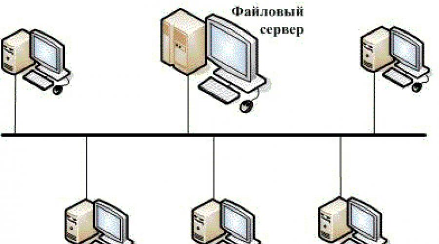
With a bus topology, the information transmission medium is presented in the form of a communication path, accessible to all workstations, to which they must all be connected. All workstations can communicate directly with any workstation on the network.
fig.3 Bus topology
Workstations at any time, without interrupting the operation of the entire computer network, can be connected to it or disconnected. The functioning of a computer network does not depend on the state of a separate workstation.
In the standard situation for an Ethernet bus network, a thin cable or a Cheapernet cable with a tee connector is often used. Turning off and especially connecting to such a network requires a bus break, which causes a disruption in the circulating flow of information and a system hang.
The tree structure of the LAN.
Along with the well-known topologies of computer networks ring, star and bus, a combined one is also used in practice, for example, a tree structure. It is formed mainly in the form of combinations of the above topologies of computer networks. The base of the computer network tree is located at the point (root) where information communication lines (tree branches) are collected.
Computing networks with a tree structure are used where it is impossible to directly apply the basic network structures in their pure form.
fig.4 Tree structure
3 .3. Network devices and means of communication.
The most commonly used means of communication are twisted pair, coaxial cable, and fiber optic lines. When choosing the type of cable, the following indicators are taken into account:
· installation and maintenance cost,
· information transfer rate,
· restrictions on the value of the information transmission distance without additional repeater amplifiers (repeaters),
· data transmission security.
The main problem is to achieve these indicators at the same time, for example, the highest data transfer rate is limited by the maximum possible data transfer distance, which still provides the required level of data protection. Easy scalability and ease of expansion of the cable system affect its cost.
3.3.1. Types of cables used.
twisted pair.
The cheapest cable connection is a twisted two-wire wire connection often referred to as a "twisted pair" (twisted pair). It allows you to transfer information at speeds up to 10 Mbit / s. It can be easily increased, but is not protected from interference. The cable length cannot exceed 1000 m at a transmission rate of 1 Mbps. The advantages are low price and ease of installation. To improve the noise immunity of information, a shielded twisted pair is often used, i.e. a twisted-pair cable placed in a shield, similar to the screen of a coaxial cable. This increases the cost of twisted pair and brings its price closer to the price of coaxial cable.
Ethernet cable.
The Ethernet cable is also a 50 ohm coaxial cable. It is also called thick Ethernet (thick), yellow cable (yellow cable) or 10BaseT5. It uses a 15 pin standard switch. Due to its noise immunity, it is an expensive alternative to conventional coaxial cables. The maximum available distance without a repeater does not exceed 500 m, and the total distance of the Ethernet network is about 3000 m. The Ethernet cable, due to its backbone topology, uses only one terminating resistor at the end.
Cheapernet cable.
Cheaper than an Ethernet cable is the Cheapernet cable or, as it is often called, thin Ethernet or 10BaseT2 connection. It is also a 50-ohm coaxial cable with a transmission rate of ten million bits per second.
When connecting segments of a Shearegnet cable, repeaters are also required. Computing networks with Cheapernet-cable have a low cost and minimal costs when building up. Network board connections are made using widely used small bayonet connectors (CP-50). Additional shielding is not required. The cable is connected to the PC using tee connectors (T-connectors).
The distance between two workstations without repeaters can be a maximum of 300 m, and the total distance for a network on a Cheapernet cable is about 1000 m.
fiber optic lines.
The most expensive are optical conductors, also called fiberglass cable. The speed of information propagation through them reaches several billion bits per second. Permissible removal of more than 50 km. There is practically no external influence of interference. On this moment this is the most expensive LAN connection. They are used where electromagnetic interference fields occur or information is required to be transmitted over very long distances without the use of repeaters. They have anti-fluff properties, since the tapping technique in fiber optic cables is very complex. Optical conductors are combined in JIBC using a star connection.
Network adapter cards act as a physical interface, or connection, between a computer and a network cable. Boards are inserted into special sockets (expansion slots) of all computers and servers. To provide a physical connection between the computer and the network, a network cable is connected to the appropriate connector, or port, of the card (after it is installed). Purpose of the network adapter board:
Preparing data from a computer for transmission network cable;
Transferring data to another computer;
Data flow control between computer and cable system;
The network adapter card takes data from the network cable and translates it into a form understandable by the computer's central processing unit.
The network adapter card consists of hardware and firmware stored in ROM (Read Only Memory). These programs implement the functions of the logical link control sublayers and access control to the medium of the link layer of the OSI model.
The splitter serves as the central node in networks with a star topology.
When transmitting over a network cable electrical signal gradually weakens (fades out). And, it is distorted to such an extent that the computer ceases to perceive it. To prevent signal distortion, a repeater is used that amplifies (restores) the weakened signal and transmits it further along the cable. Repeaters are used in networks with a bus topology.
3.4. Types of building networks by methods of information transfer.
Local network Token Ring.
This standard was developed by IBM. The transmission medium is unshielded or shielded twisted pair (UPT or SPT) or optical fiber. Data transfer rate 4 Mbps or 16 Mbps. As a method of controlling the access of stations to the transmission medium, the method is used - a token ring (Token Ring). The main provisions of this method:
Devices are connected to the network in a ring topology;
All devices connected to the network can only transmit data if they receive permission to transmit (token);
At any given time, only one station in the network has this right.
There are three main types of packets used in IBM Token Ring:
Package control / data (Data / Command Frame);
Marker (Token);
Reset package (Abort).
Control/Data package. With the help of such a packet, data or network control commands are transmitted.
Marker. The station can start data transmission only after receiving such a packet. There can be only one marker in one ring and, accordingly, only one station with the right to transmit data.
Reset package. The sending of such a packet calls the termination of any transmissions.
Computers can be connected in a network in a star or ring topology.
Ethernet local area network.
The Ethernet specification was proposed by the Xerox Corporation in the late seventies. Later, Digital Equipment Corporation (DEC) and Intel Corporation joined this project. In 1982, the specification for Ethernet version 2.0 was published. On the basis of Ethernet and the IEEE Institute, the IEEE 802.3 standard was developed. The differences between them are minor.
Basic principles of work.
At the logical level, Ethernet uses a bus topology:
All devices connected to the network are equal, i.e. any station can start transmission at any time (if the transmission medium is free);
Data transmitted by one station is available to all stations on the network.
10BaseT
In 1990, the IEEE released the 802.3 specification for building a twisted-pair Ethernet network. 10 BaseT (10 - transmission rate 10 Mbps, Base - narrowband, T - twisted pair) - an Ethernet network that usually uses unshielded twisted pair (UTP) to connect computers. Most networks of this type are built in the form of a star, but the signaling system is a bus, like other Ethernet configurations. Typically, a 10BaseT network splitter acts as a multiport repeater. Each computer connects to the other end of a cable connected to a splitter and uses two pairs of wires, one for receiving and one for transmitting.
The maximum length of a 10BaseT segment is 100 m. The minimum cable length is 2.5 m. A 10BaseT LAN can serve up to 1024 computers.
To build a 10BaseT network, use:
RJ-45 connectors at cable ends.
The distance from the workstation to the splitter is no more than 100 m.
10Base2
According to the IEEE 802.3 specification, this topology is called 10Base2 (10 is a 10Mbps transmission rate, Base is narrowband transmission, 2 is a transmission over a distance approximately twice as long as 100m (actual distance 185m).
This type of network is focused on thin coaxial cable, or thin Ethernet, with a maximum segment length of 185 m. The minimum cable length is 0.5 m. In addition, there is a limit on the maximum number of computers that can be connected on a 185 m cable segment - 30 things.
Thin Ethernet Cable Components:
BNC barrel - connectors (connectors);
BNC T - connectors;
BNC - terminators.
Thin Ethernet networks usually have a bus topology. The IEEE standards for thin Ethernet do not require a transceiver cable between the T-connector and the computer. Instead, the T-connector is located directly on the network adapter board.
BNC barrel - connector, connecting cable segments, allows you to increase its overall length. However, their use should be kept to a minimum as they degrade signal quality.
Thin Ethernet networking is a cost-effective way to implement networks for small offices for workgroups. The cable used in this type of networks is relatively inexpensive, easy to install, and easy to configure. A thin Ethernet network can support up to 30 nodes (computers and printers) per segment.
A thin Ethernet network can consist of a maximum of five cable segments connected by four repeaters, but workstations can be connected to only three segments. Thus, two segments remain reserved for repeaters, they are called inter-repeater links. This configuration is called the 5-4-3 rule.
10Base5.
According to the IEEE specification, this topology is called 10Base5 (10 is 10Mbps transmission rate, Base is narrowband transmission, 5 is 500-meter segments (5 times 100 meters)). There is another name for it - standard Ethrnet.
Networks on thick coaxial cable (thick Ethrnet) usually use a bus topology. Thick Ethernet can support up to 100 nodes (workstations, repeaters, etc.) per backbone segment. Trunk, or trunk segment, is the main cable to which transceivers are connected with workstations and repeaters connected to them. A thick Ethernet segment can be 500 meters long with a total network length of 2500 meters. Distances and tolerances for thick Ethernet are greater than for thin Ethernet.
Cable system components:
Transceivers. Transceivers, providing communication between the computer and the main LAN cable, are combined with a "vampire tooth" connected to the cable.
Transceiver cables. The transceiver cable (drop cable) connects the cable to the network adapter card.
DIX - connector, or AUI - connector. This connector is located on the transceiver cable.
Barrel - connectors and terminators.
A thick Ethernet network can consist of a maximum of five backbone segments connected by repeaters (according to the IEEE 802.3 specification), but computers can be connected to only three segments. When calculating the total length of the thick Ethernet cable, the length of the transceiver cable is not taken into account, i.e. only the length of the thick Ethernet cable segment is taken into account. The minimum distance between adjacent connections is 2.5 meters. This distance does not include the length of the transceiver cable. Thick Ethernet was designed for building a LAN within a large department lil of the entire building.
Typically, large networks share thick and thin Ethernet. Thick Ethernet works well as a backbone, and thin Ethernet is used for branching segments. You probably remember that thick Ethernet has a larger copper core and can transmit signals over longer distances than thin Ethernet. The transceiver is connected to the “thick Ethernet” cable, AUI - the connector of the transceiver cable is included in the repeater. The branching segments of the “thin Ethernet” are connected to the repeater, and computers are already connected to them.
10BaseFL.
10BaseFL (10 - 10 Mbps transmission rate, Base - narrowband transmission, FL - fiber optic cable) is an Ethernet network in which computers and repeaters are interconnected by fiber optic cable.
The main reason for the popularity of 10BaseFL is the ability to lay cable between repeaters over long distances (for example, between buildings). The maximum length of a 10BaseFL segment is 2000 meters.
8-pin modular sockets (modular jack) are used to connect cables. 8-pin RJ-45 connectors are installed on the cables using special crimping pliers.
Fig.5 Modular socket Rice. 6 8-pin RJ-45 connectors
When exchanging data between two devices, the receiver of one of the devices must be connected to the transmitter of the other and vice versa. Pair twisting (cross-over) is usually implemented inside one of the devices when wiring the cable in the connector. Some ports of hubs and switches support the ability to change the type of wiring in the connector (MDI-X or Normal). Computer network adapters usually do not allow you to change the type of port pinout and are referred to as devices with an MDI or Uplink port.
Figures 7 and 8 show straight and cross-over port connection options.
Cable joints must provide at least 750 connection-disconnect cycles.
The category of the patch cable must match the category of the cable in the horizontal system.
· Patch cables must have stranded conductors to ensure sufficient flexibility.
Cable routing
1. In order to avoid breaking the conductors, the tension should not exceed 110N.
2. The bending radius should not be less than 4 cable diameters for horizontal wiring.
3. Avoid pinching cables, which can be caused by:
Twisting cables during installation;
Inaccurate hanging of cables;
Too dense laying of cables in the channel;
Cable specifications: diameter 0.2", RG-58A/U 50 Ohm;
Acceptable connectors: BNC;
Maximum segment length: 185 m;
Minimum distance between nodes: 0.5 m;
Maximum number of nodes in a segment: 30
Cable specifications are shown in table 1.
Table 1. 10BASE2 (ThinNet) RG 58 A/U and RG 58 C/U cable specifications
Table 2. Electrical Specifications for Category 3, 4, and 5 Cables
Wave impedance: 50 ohm
Maximum segment length: 500 meters
Minimum distance between nodes: 2.5 m
Maximum number of nodes in a segment: 100
AUI cables are used to connect AUI ports to thick coaxial cable trunks. The maximum cable length is 50 meters.
Table 3 AUI Cable Specifications
Conclusion
In this paper, the main components of the LAN were considered. To date, the development and implementation of IVS is one of the most interesting and important tasks in the field of information technology. The need for operational information is growing more and more, the traffic of networks of all levels is constantly growing. In this regard, new technologies for transferring information to IVS are emerging. Among the latest discoveries, it should be noted the possibility of data transmission using conventional power lines, with this method allows you to increase not only the speed, but also the reliability of transmission. Network technologies are developing very rapidly, in connection with which they begin to stand out as a separate information industry. Scientists predict that the next achievement of this industry will be the complete exclusion of other means of information transmission (television, radio, print, telephone, etc.). These "obsolete" technologies will be replaced by a computer, it will be connected to some global information flow, perhaps even the Internet, and from this flow it will be possible to obtain any information in any representation. Although it cannot be argued that everything will be exactly like this, since network technologies, like computer science itself, is the youngest science, and everything young is very unpredictable.
Bibliography:
1. N. Malykh. Local networks for beginners: Textbook. – M.: INFRA-M, 2000.
2. N. Olifer, V. Olifer. Basic technologies of local networks. Textbook. - M.: Dialogue - MEPhI, 1996.
3. Computer networks. Training course / Per. from English. - M .: Publishing Department "Russian Edition" LLP "Channel Trading Ltd.", 1997.
4. Barry Nance. Computer networks: Per. from English. - M: Eastern Book Company, 1996.
Application
Option 5. .
Option 5.
Table 5
Turnover sheet for accounting
diet food
| Product name | Unit | Incoming balance | Turnovers | Outgoing balance | |
| Coming | Consumption | ||||
In hierarchical local area networks, there are one or more special computers - servers that store information shared by various users.
Server in hierarchical networks is a persistent storage of shared resources. The server itself can only be a client of a server at a higher level in the hierarchy. Therefore, hierarchical networks are sometimes referred to as dedicated server networks. Servers are usually high-performance computers, possibly with several processors working in parallel, with high-capacity hard drives, with a high-speed network card (100 Mbps or more). Computers from which information on the server is accessed are called stations or clients.
LANs are classified according to their purpose:
Terminal service networks. They include computers and peripheral equipment used in exclusive mode by the computer to which it is connected, or be a network-wide resource.
Networks on the basis of which production management systems and institutional activities are built. They are united by the MAP/TOP standards group. The MAP describes the standards used in industry. TOP describes standards for networks used in office networks.
Networks that connect automation systems, design. The workstations of such networks are usually based on sufficiently powerful personal computers, such as Sun Microsystems.
Networks on the basis of which distributed computing systems are built.
All LANs operate in the same standard adopted for computer networks - the Open Systems Interconnection (OSI) standard.
Basic model osi (Open System Interconnection)
In order to interact, people use a common language. If they cannot speak directly to each other, they use appropriate aids to convey messages.
The steps shown above are necessary when a message is passed from a sender to a receiver.
In order to set in motion the process of data transmission, machines with the same data coding and connected to one another were used. For a unified presentation of data in the communication lines through which information is transmitted, the International Organization for Standardization (eng. ISO - International Standards Organization) has been formed.
ISO is intended to provide a model for an international communication protocol within which international standards can be developed. For a visual explanation, we divide it into seven levels.
International Organization for Standardization (ISO) has developed base model open systems interactions (English Open Systems Interconnection (OSI)). This model is the international standard for data transmission.
The model contains seven separate levels:
Level 1: physical- bit protocols for information transfer;
Level 2: channel- formation of personnel, management of access to the environment;
Level 3: network- routing, data flow control;
Level 4: transport- ensuring the interaction of remote processes;
Level 5: session- support for dialogue between remote processes;
Level 6: submission data - interpretation of transmitted data;
Level 7: applied- user data management.
The main idea of this model is that each level has a specific role, including the transport environment. Thanks to this, the general task of data transmission is divided into separate, easily visible tasks. The necessary agreements for communication of one level with the above and below are called the protocol.
Since users need effective management, the computer network system is presented as a complex structure that coordinates the interaction of user tasks.
With the above in mind, the following layer model can be deduced with administrative functions running in the user application layer.
The individual layers of the base model run downward from the data source (from layer 7 to layer 1) and upward from the data sink (from layer 1 to layer 7). The user data is passed to the lower layer, along with a layer-specific header, until the last layer is reached.
On the receiving side, the incoming data is analyzed and, as necessary, transferred further to the higher layer until the information is transferred to the user application layer.
Level 1Physical.
The physical layer defines the electrical, mechanical, functional and procedural parameters for physical communication in systems. physical connection and the operational readiness that goes with it is the main function of the 1st level. Physical layer standards include CCITT recommendations V.24, EIA RS232 and X.21. The ISDN (Integrated Services Digital Network) standard will play a defining role in the future for data transfer functions. As a data transmission medium, a three-core copper wire (shielded twisted pair), a coaxial cable, an optical fiber conductor and a radio relay line are used.
Level 2Channel.
The link layer forms from the data transmitted by the 1st layer, the so-called "frames" of the sequence of frames. At this level, access control to the transmission medium used by several computers, synchronization, error detection and correction are carried out.
Level 3Network.
The network layer establishes communication in a computer network between two subscribers. The connection occurs due to routing functions that require the presence of a network address in the packet. The network layer must also provide error handling, multiplexing, and data flow control. The best-known standard related to this layer is CCITT Recommendation X.25 (for public packet networks).
Level 4Transport.
The transport layer supports the continuous transfer of data between two interacting user processes. Transport quality, transmission error-free, computer network independence, end-to-end transport service, cost minimization and communication addressing guarantee uninterrupted and error-free data transmission.
Level 5session.
The session layer coordinates the reception, transmission and issuance of a single communication session. Coordination requires control of operating parameters, data flow control of intermediate storages and dialogue control to ensure the transfer of available data. In addition, the session layer additionally contains the functions of managing passwords, calculating fees for using network resources, managing dialogue, synchronizing and canceling communication in a transmission session after a failure due to errors in the lower layers.
Level 6 Data representations.
The presentation layer is for data interpretation; and preparing data for the user application layer. This layer converts the data from the frames used for data transmission to the screen or printer format of the end system.
Level 7Applied.
In the application layer, it is necessary to provide users with already processed information. This can be handled by system and user application software.
To transmit information over communication lines, the data is converted into a chain of successive bits (binary coding using two states: "0" and "1").
Transmitted alphanumeric characters are represented using bit combinations. The bit patterns are arranged in a specific codebook containing 4-, 5-, 6-, 7-, or 8-bit codes.
The number of characters represented in a move depends on the number of bits used in the code: a 4-bit code can represent a maximum of 16 values, a 5-bit code can represent 32 values, a 6-bit code can represent 64 values, a 7-bit code can represent 128 values, and an 8-bit code - 256 alphanumeric characters.
When transferring information between the same computing systems and different types of computers, the following codes are used:
At the international level, the transmission of character information is carried out using 7-bit encoding, which allows you to encode upper and lower case letters of the English alphabet, as well as some special characters.
National and special characters cannot be represented using a 7-bit code. The most commonly used 8-bit code is used to represent national characters.
For a correct and therefore complete and error-free transmission of data, it is necessary to adhere to agreed and established rules. All of them are specified in the data transfer protocol.
The data transfer protocol requires the following information:
Synchronization
Synchronization is understood as a mechanism for recognizing the beginning of a data block and its end.
Initialization
Initialization is understood as the establishment of a connection between interacting partners.
blocking
Blocking is understood as the splitting of transmitted information into data blocks of a strictly defined maximum length (including the identification marks of the beginning of the block and its end).
Addressing
Addressing provides identification of the various data equipments used, which exchange information with each other during interaction.
Error detection
By error detection is meant the setting of the parity bits and hence the calculation of the parity bits.
Block numbering
The current numbering of blocks allows you to set erroneously transmitted or lost information.
Data flow control
Data flow control serves to distribute and synchronize information flows. So, for example, if there is not enough space in the data device's buffer, or the data is not processed fast enough in peripherals (such as printers), messages and/or requests accumulate.
Recovery Methods
After the data transfer process is interrupted, recovery methods are used to return to a certain position for retransmission of information.
Access permission
Distribution, control and management of data access restrictions are the responsibility of the access permission point (for example, "transmit only" or "receive only").
Network devices and communications
The most commonly used means of communication are twisted pair, coaxial cable, fiber optic lines. When choosing the type of cable, the following indicators are taken into account:
installation and maintenance cost,
information transfer rate,
Restrictions on the value of the information transmission distance (without additional repeater amplifiers (repeaters)),
data transmission security.
The main problem is to achieve these indicators at the same time, for example, the highest data transfer rate is limited by the maximum possible data transfer distance, which still provides the required level of data protection. Easy scalability and ease of expansion of the cable system affect its cost /
twisted pair
The cheapest cable connection is a twisted two-wire wire connection often referred to as a "twisted pair" (twisted pair). It allows you to transfer information at speeds up to 10 Mbps, is easily scalable, but is noise-immune. The cable length cannot exceed 1000 m at a transmission rate of 1 Mbps. The advantages are low price and problem-free installation. To improve the noise immunity of information, a shielded twisted pair is often used, i.e. a twisted-pair cable placed in a shield, similar to the screen of a coaxial cable. This increases the cost of twisted pair and brings its price closer to the price of coaxial cable.
Coaxial cable
The coaxial cable has average price, well anti-jamming and is used for communication over long distances (several kilometers). The information transfer rate is from 1 to 10 Mbps, and in some cases it can reach 50 Mbps. Coaxial cable is used for basic and broadband transmission of information.
Broadband coaxial cable
Broadband coaxial cable is immune to interference, easy to grow, but its price is high. The information transfer rate is 500 Mbps. When transmitting information in the base frequency band over a distance of more than 1.5 km, an amplifier, or the so-called repeater (repeater), is required. Therefore, the total distance during the transmission of information increases to 10 km. For computer networks with a bus or tree topology, a coaxial cable must have a terminating resistor (terminator) at the end.
Ethernet cable
The Ethernet cable is also a 50 ohm coaxial cable. It is also called thick Ethernet (thick) or yellow cable (yellow cable). It uses a 15 pin standard switch. Due to its noise immunity, it is an expensive alternative to conventional coaxial cables. The maximum available distance without a repeater does not exceed 500 m, and the total distance of the Ethernet network is about 3000 m. The Ethernet cable, due to its backbone topology, uses only one terminating resistor at the end.
Cheapernet cable
Cheaper than an Ethernet cable is the Cheapernet cable or, as it is often called, thin Ethernet connection. It is also a 50 ohm coaxial cable with a transmission rate of ten million bps.
When connecting segments of a Shearegnet cable, repeaters are also required. Computing networks with Cheapernet-cable have a low cost and minimal costs when building up. Network board connections are made using widely used small bayonet connectors (CP-50). Additional shielding is not required. The cable is connected to the PC using tee connectors (T-connectors).
The distance between two workstations without repeaters can be a maximum of 300 m, and the total distance for a network on a Cheapernet cable is about 1000 m.
Modern computer technologies cannot be imagined without combining all kinds of devices in the form of stationary terminals, laptops or even mobile devices in single network. Such an organization allows not only to quickly exchange data between different devices, but also to use the computing capabilities of all units of equipment connected to the same network, not to mention the possibility of access to peripheral components such as printers, scanners, etc. But what are the principles for such a combination? To understand them, it is necessary to consider the local network, often called the topology, which will be discussed further. To date, there are several main classifications and types of combining any devices that support network technologies into one network. Of course, we are talking about those devices on which special wired or wireless network adapters and modules.
Schemes of local computer networks: the main classification
First of all, in considering any type of organization of computer networks, it is necessary to start solely from the method of combining computers into a single whole. There are two main directions used in creating a local network diagram. The network connection can be either wired or wireless.
In the first case, special coaxial cables or twisted pairs are used. This technology is called Ethernet connection. However, if coaxial cables are used in the local computer network, their maximum length is about 185-500 m at a data transfer rate of not more than 10 Mbps. If twisted pairs of classes 7, 6 and 5e are used, their length can be 30-100 m, and the throughput ranges from 10-1024 Mbps.

The wireless scheme for connecting computers in a local network is based on the transmission of information via a radio signal, which is distributed between all connected devices, distributing devices, which can be routers (routers and modems), access points (regular computers, laptops, smartphones, tablets), switching devices (switches, hubs), signal repeaters (repeaters), etc. With this organization, fiber optic cables are used that are connected directly to the main signal-distributing equipment. In turn, the distance over which information can be transmitted increases to about 2 km, and in the radio frequency range, frequencies of 2.4 and 5.1 MHz are mainly used (IEEE 802.11 technology, better known as Wi-Fi).
Wired networks are considered to be more secure from external influences, since it is not always possible to directly access all terminals. Wireless structures in this regard lose quite a lot, because if desired, a competent attacker can easily calculate network password, access the same router, and through it to get to any device that is currently using a Wi-Fi signal. And very often in the same state structures or in the defense enterprises of many countries, the use of wireless equipment is strictly prohibited.
Classification of networks according to the type of connection between devices
Separately, it is possible to single out a fully connected topology of schemes for connecting computers in a local network. Such a connection organization implies only that absolutely all terminals included in the network have a connection with each other. And as it is already clear, such a structure is practically not protected in terms of external intrusion or when intruders penetrate the network through special virus worms or spyware applets that could initially be recorded on removable media, which the same inexperienced employees of enterprises unknowingly could connect to your computers.
That is why other connection schemes in the local network are most often used. One of these can be called a cellular structure from which certain initial connections have been removed.
General scheme for connecting computers in a local network: the concept of the main types of topology
Now let's take a quick look at wired networks. They can use several of the most common types of local area networking schemes. The most basic types are star, bus, and ring structures. True, it is the first type and its derivatives that have received the greatest use, but mixed types of networks can often be found, where combinations of all three main structures are used.
Star topology: pros and cons
The “star” local network scheme is considered the most common and widely used in practice when it comes to using the main types of connection, so to speak, in its purest form.

The essence of such a combination of computers into a single whole is that they are all connected directly to the central terminal (server) and do not have any connections with each other. Absolutely all transmitted and received information passes directly through the central node. And it is this configuration that is considered the most secure. Why? Yes, only because the introduction of the same viruses into the network environment can be done either from the central terminal, or get through it from another computer device. However, it looks very doubtful that in such a scheme of the local network of an enterprise or government institution a high level of protection of the central server will not be provided. And injecting spyware from a separate terminal will only work if you have physical access to it. In addition, quite serious restrictions can be imposed on each network computer from the side of the central node, which can be especially often observed when using network operating systems, when computers do not even have hard disks, and all the main components of the applied OS are loaded directly from the main terminal.
But even here there are drawbacks. First of all, this is due to the increased financial costs for laying cables if the main server is not located in the center of the topological structure. In addition, the speed of information processing directly depends on the computing capabilities of the central node, and if it fails, respectively, on all computers included in the network structure, communications are broken.
Bus scheme
The connection scheme in the local network according to the “bus” type is also one of the most common, and its organization is based on the use of a single cable, through the branches of which all terminals, including the central server, are connected to the network.

The main disadvantage of such a structure can be called the high cost of laying cables, especially for those cases when the terminals are at a sufficiently large distance from each other. But if one or more computers fail, communications between all other components in the network environment are not broken. In addition, when using such a scheme, the local network passing through the main channel is very often duplicated in different areas, which makes it possible to avoid its damage or the impossibility of its delivery to its destination. But security in such a structure, alas, suffers quite a lot, since malicious virus codes can penetrate all other machines through the central cable.
Ring structure
The ring scheme (topology) in a sense can be called obsolete. To date, it is not used in almost any network structure (except perhaps only in mixed types). This is due precisely to the very principles of combining individual terminals into one organizational structure.

Computers are connected to each other in series and with only one cable (roughly speaking, at the input and output). Of course, such a technique reduces material costs, but if at least one network unit fails, the integrity of the entire structure is violated. If I may say so, in a certain area where there is a damaged terminal, the transmission (passage) of data simply stops. Accordingly, when dangerous computer threats penetrate the network, they pass from one terminal to another in the same way. But in case of presence at one of the sites reliable protection The virus will be eliminated and will not pass further.
Mixed types of networks
As mentioned above, the main types of local area network schemes in their pure form are practically not found. Mixed types look much more reliable in terms of security, cost, and ease of access, in which elements of the main types of network diagrams may be present.

So, very often you can find networks with a tree structure, which initially can be called a kind of “star”, since all branches come from one point, called the root. But the organization of branches in such a LAN connection scheme can contain both ring and bus structures, dividing into additional branches, often defined as subnets. It is clear that such an organization is quite complex, and when creating it, it is necessary to use additional technical devices such as network switches or splitters. But, as they say, the end justifies the means, because thanks to such a complex structure, important and confidential information can be protected very reliably by isolating it in subnet branches and practically restricting access to it. The same applies to the failure of components. With such a construction of local network schemes, it is not necessary to use only one central node. There can be several of them, and with completely different levels of protection and access, which further increases the degree of overall security.
Logistic topology
When organizing network structures, it is especially important to pay attention to the methods of data transmission used. In computer terminology, such processes are usually called logistic or logical topology. At the same time, the physical methods of information transfer in various structures can differ significantly from the logical ones. It is logistics, in essence, that determines the routes of reception / transmission. Very often it can be observed that when building a network in the form of a "star", information exchange is carried out using a bus topology, when the signal can be received simultaneously by all devices. In ring logical structures, situations can be encountered when signals or data are received only by those terminals for which they are intended, despite even sequential passage through all related links.
The most famous networks
So far, only the construction of local network schemes based on Ethernet technologies, which is in the simple expression uses addresses, protocols, and TCP/IP stacks. But after all, in the world you can find a huge number of network structures that have principles different from the above. network organization. The best known of all (except Ethernet using a logical bus topology) are Token Ring and Arcnet.

The Token Ring network structure was once developed by the notorious IBM company and is based on the logical scheme of the local network “token ring”, which determines the access of each terminal to the transmitted information. Physically, a ring structure is also used, but it has its own characteristics. To combine computers into a single whole, it is possible to use either twisted pair or fiber optic cable, but the data transfer rate is only 4-16 Mbps. On the other hand, the "star" type marker system allows to transmit and receive data only to those terminals that have the right to do so (marked with a marker). But the main disadvantage of such an organization is that in certain moment only one station can have such rights.
No less interesting is the Arcnet LAN scheme, created in 1977 by Datapoint, which many experts call the most inexpensive, simple and very flexible structure.

To transfer information and connect computers, coaxial or fiber optic cables can be used, but the possibility of using a twisted pair cable is also not excluded. True, in terms of the speed of reception / transmission, this structure cannot be called particularly productive, since at the maximum packet exchange can be carried out at a connection speed of no more than 2.5 Mbps. As physical connection the "star" circuit is used, and in the logical one - the "marker bus". With the rights to receive / transmit, the situation is exactly the same as in the case of Token Ring, except that the information transmitted from one machine is available to absolutely all terminals included in the network environment, and not to any one machine.
Brief information about setting up a wired and wireless connection
Now let's briefly look at some important points creation and application of any of the described local network schemes. Third-party programs when using any of the known operating systems are not needed to perform such actions, since the main tools are provided in their standard sets from the very beginning. However, in any case, it is necessary to take into account some important nuances regarding the configuration of IP addresses, which are used to identify computers in network structures. There are only two varieties - static and dynamic addresses. The first, as the name already implies, are constant, and the second can change with each new connection, but their values are exclusively in the same range set by the communication service provider (provider).
In wired corporate networks to provide high speed data exchange between network terminals, static addresses are most often used, assigned to each machine located on the network, and when organizing a network with wireless connection usually dynamic addresses are involved.
To set the specified parameters of a static address in Windows systems, the parameters of the IPv4 protocol are used (in the post-Soviet space, the sixth version has not yet become particularly widespread).

It is enough to write an IP address for each machine in the protocol properties, and the subnet mask and default gateway parameters are common (unless a tree structure with multiple subnets is used), which looks very convenient in terms of quick connection setup. Despite this, dynamic addresses can also be used.

They are assigned automatically, for which there is a special item in the TCP / IP protocol settings, at each specific point in time they are assigned to network machines directly from the central server. The range of allocated addresses is provided by the provider. But this does not mean at all that the addresses are repeated. As you know, there cannot be two identical external IPs in the world, and in this case we are talking either about the fact that they change only within the network or are transferred from one machine to another when some external address is free.
In the case of wireless networks, when routers or access points are used for the initial connection, distributing (broadcasting or amplifying) the signal, the setup looks even easier. The main condition for this type of connection is to set the automatic receipt of an internal IP address. Without this, the connection will not work. The only changeable parameter is the DNS server addresses. Despite the initial setting of their automatic receipt, it is often (especially when the connection speed is reduced) that it is recommended to set such parameters manually, using, for example, free combinations distributed by Google, Yandex, etc.
Finally, even if there is only a certain set of external addresses by which any computer or mobile device is identified on the Internet, they can also be changed. For this, there are many special programs. The local network scheme can have any of the above variations. And the essence of using such tools, which are most often either VPN clients or remote proxy servers, is to change the external IP, which, if anyone does not know, has a clear geographical reference, to an unoccupied address located in a completely different location (even at the end of the world). You can use such utilities directly in browsers (VPN clients and extensions) or make changes at the level of the entire operating system(for example, using the SafeIP application) when some applications running in the background need to access Internet resources that are blocked or inaccessible for a certain region.
Epilogue
Summing up all of the above, several main conclusions can be drawn. The first and most important thing is that the basic connection schemes are constantly changing, and they are almost never used in the initial version. The most advanced and most secure are complex tree structures, in which several subordinate (dependent) or independent subnets can additionally be used. Finally, no matter what anyone says, present stage development computer technology wired networks, even despite the high financial costs of their creation, it is still a cut above the level of security than the simplest wireless ones. But wireless network have one indisputable advantage - they allow you to combine computers and mobile devices that can be geographically distant from each other over very long distances.