Do-it-yourself satellite dish signal amplifier. How to improve satellite dish signal
Read also
Let's find out why we need signal increase co .
If you want to increase the number of channels, then this is unlikely to help you. But there is a case when they show only with a strong signal, and a weak one either “crumbles” or does not show at all. In this case, increasing the signal will also help increase the number of channels.
Another thing is if the picture on all channels “crumbles”, or even does not show at all, which indicates that there is no signal or it is weak.
There can be several reasons for this signal behavior. And removing them is usually not difficult.
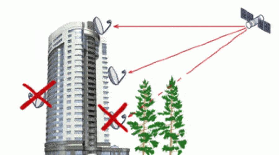
 There is also a case when for a long time everything showed perfectly for you, and now the signal has begun to disappear more and more often, especially in summer. Stand in front of the antenna and see if there is a tree nearby in the direction of the antenna, which could grow in a few years and close the passage for the signal from the satellite to the antenna, especially in summer, when the crown of the tree is compacted due to foliage. In this case, it is enough to remove the interfering branch, and if necessary, the entire plant, otherwise move the antenna to another place.
There is also a common quality issue. It consists in the fact that under the influence of temperatures, the cable braid begins to crack and fall off, or even easier, it begins to fray on the descent from the roof in an unprotected place, due to this moisture gets inside the cable, the braid begins to oxidize and rot. In this case, the signal begins to gradually weaken. It is necessary to replace the cable with a better one and during installation pay attention to the fastening so that the wind cannot loosen and fray the cable.
It is necessary to pay attention to the length of the cable as well. the longer the cable, the stronger the attenuation of the signal, again as a result of poor broadcasting of television channels from. In this case, the signal quality near the antenna will satisfy, but it simply may not be in the room. If your TV is located at some distance (50m-100m) from the antenna, you need to buy a better cable with the least attenuation, and if necessary, install a signal amplifier.

The amplifier should be installed in a cable break at a distance of 1.5-2 meters from the converter.
Breakdowns rarely occur, but it happens even from moisture getting through the cable. The cable, like a capillary, draws in moisture, and it accumulates in the lowest place - this is the connection to the receiver. In the event of a receiver failure, no one can help you except the master. Visually, the failure of the receiver can be diagnosed by connecting and disconnecting the cable to the receiver, the signal scale should still somehow respond to these actions, provided that all other equipment is working properly. If the power supply is broken, the receiver simply does not turn on, but it happens that the receiver turns on, but there may be no signal and the picture just freezes.
Well, what if everyone checked everything is working in order, but the signal is still not enough.
In this case, the size of the antenna mirror can affect the signal increase, in other words, it is easier to purchase an antenna with a larger diameter. The larger the antenna, the larger the signal reflection area, respectively, and the signal strength itself increases. To do it right, you need to calculate its dimensions depending on the strength of the transponder broadcast from the satellite, or use ready-made calculations.
This is actually a very important subject in successful TV viewing.
In short, a satellite dish is our everything! No way without her!
However, from correct installation antenna depends on the reliable reception of the satellite signal.
If according to Hamlet: "To beat or not to beat, such a question ..."
Whether it will catch a signal from a satellite or not depends on your skill.
And so, let's go.
Position satellite dish horizontally. That is, the azimuth direction of the antenna mirror, from your point of location. Which, you will determine according to the compass ( Rice. 1).
With horizontal adjustment, we will move the mirror itself (reflector), on EAST (E- east), or on WEST (W- west). In reality, this process must be combined with the vertical adjustment. I must say right away that it makes sense to call a specialist for this operation.
I did this procedure myself, a long time ago. But there were doubts about the choice of Tenene,
It makes sense to think.
Then he corrected the antenna with. Sometimes it is necessary to receive a signal immediately from . To do this, you can install simple system, consisting of several converters.
Positioning the satellite dish horizontally.
The second parameter is the position of the satellite dish, according to vertical.
That is, the angle of its inclination.
The angle of inclination of the antenna (Fig. 2) will directly depend on the height at which the satellite itself is located. So, the angle of elevation to the satellite, or as it is also called the elevation angle.

Well, if you conceived it yourself without special equipment, then something like this.
Let's start with the central head, which should be set to our Sirius. In the receiver, we set the frequencies to 11766, the speed to 27500, the polarization "H".
On the receiver you have two bands:
One signifying the connection of the dish and the signal from the satellite. The second shows the level of this signal. When the satellite dish is connected correctly, you should see the signal strength. Approximately 40%. It remains to adjust the signal quality, which we have at zero.
Let's move on to the plate and let's get started.
We turn the antenna to the left and up to the stop and in search of best level signal slowly turn from left to right until it stops.
If the signal is not found, we lower the dish by 2-3 mm along the fastener (there are marks with numbers on the fastener of the dish to the bracket for a more convenient “shooting”). And we turn from right to left until it stops, then lower it even lower and so on until a signal appears.
When you get a signal, you will see an indication bar appear. If you approximately hit the satellite, then the signal quality band will be about 21% - fix the antenna in this position. Now lower it a little and gently turn to the left. We look for changes in quality, if it decreased, then we return the antenna to its original position.
Great!
You got a signal at 40%, but this is still not enough, with such a percentage, the slightest wind or rain can interrupt your TV viewing. To increase the signal quality, turn the converter first clockwise and then counterclockwise. Look at which position the signal quality will increase.
If the mount allows, then I advise you to try to bring the converter closer to the mirror, and then move it away.
This also affects the signal quality, but usually the length of the bracket for the center converter is always adjusted to length. Normal signal quality is 65-70%.
However ... as I already wrote with a specialist, it’s more convenient.
Particular attention should be paid to the SF-500 satellite antenna tuner.
The device has a memory in which there are all the main satellites used in our regions, it is possible to edit them using the buttons on the device panel.
In a word ... a great helper when setting up satellite antennas. Specifically about the device.
Good luck Friends!
Warm days have come, a hot summer is ahead, and the May holidays have cheered up. All this leaves almost no desire to spend Sundays in the corners of a complex city apartment, but I want freedom, fresh country air, the smell of hay, grass wet with dew and the light of twinkling stars that has passed thousands of light years and reaches us through the abyss of unknown dark matter.
Accustomed to the conditions of modern civilization, I can no longer imagine a long-term life without the presence of the Internet at hand, and in the modern Russian conditions of its development in the provincial outback, its availability leaves much to be desired. Therefore, my task was to implement the possibility of obtaining broadband Internet access where it does not exist.
The country house in which I decided to install the Internet is located at a distance of 100 km from the regional center of Voronezh. And although, according to the coverage map of the operators Megafon, Beeline, MTS, communication should be present at this point, and even with 3G elements, an ordinary phone finds a signal only in certain enchanted places in the garden. In this area with a fairly confident GSM signal, only Tele2 is present. But it just so happened that Tele2 in our region does not provide unlimited tariffs access to the Internet, and limit tariffs in our time are no longer comme il faut.
I used a Huawei E1550 modem purchased long ago, unlocked for use with other telecom operators.
Below is a screenshot of the program window included with the modem, which shows the level of the Megafon 2G network signal received by the modem connected to a laptop in a clean garden (-91 dB, no EDGE signal sticks).
Below is a screenshot showing the signal level received by the modem, thrown into a tree at a height of 2.85 m (-85 dB, two EDGE signal sticks).
Thus, the task was formalized as the need to install equipment that amplifies the GSM signal in order to organize a reliable connection in the networks of the above-mentioned operators. After studying the issue of ways and methods to improve the quality of communication, I decided to stop at using a reflector antenna to reflect and concentrate the signal in the area of \u200b\u200bthe antenna of the GSM modem.
As such an antenna, I decided to use a parabolic offset (asymmetric) antenna for receiving a satellite signal Continent with a diameter of 0.66 m. Why 0.66 m? Antennas with a diameter of 0.5 m have a gain of ~18 dB, 0.6 m about 20 dB, 0.9 m about 23 dB. Installing an antenna with a diameter of 0.8 m or more is a rather troublesome task (I already had to install an antenna of 0.8 m for the Continent). A small antenna with a diameter of 0.5 m was considered to have insufficient gain. Therefore, I settled on a size of 0.6 m, but only 0.66 m was available in the store. Thus, the approximate gain of this antenna should be about 21 dB.
Then the choice was between two options - install an irradiator on the antenna to receive the GSM signal and modify the GSM modem by soldering an adapter to it for connecting an external antenna (as described ), or place the modem directly on the antenna without modification.
The advantages of the first method are the best lightning protection, regular placement of the receiving path components, sufficient cable length to the computer to place the antenna in any convenient place. The disadvantages include the increased cost and the need to modify the modem. The second method has an advantage - ease of use, but has an important drawback - the lack of lightning protection, which can lead to failure of both the modem itself and the computer's usb port, as well as a limitation on the length of the usb cable.
If you close your eyes to lightning protection and do not use a computer during a thunderstorm with a high probability of a lightning strike, then the second method outweighs the scales and it was I who used it to implement the idea.
WARNING! When repeating the design, you assume the risk of a lightning strike into the modem and putting it and its associated equipment out of action!
As a cable connecting the computer and the modem, I used a 5-meter usb extension cable with a ferrite ring at the end.
Initially, I installed the modem in a standard feed mount on the antenna. But this installation method, for some reason, did not bring any significant changes in the quality of the received signal. I had to experiment for a long time to find the most successful modem position, relative to the antenna, at which at least some gain effect was noted. As it turned out, it's not so easy. The distance from the modem to the antenna surface greatly affects the gain. Literally 2-3 cm further or closer and the difference in the level of the received signal reaches 10-15 dB. Similarly, the rotation of the modem plane relative to the antenna strongly affects. As a result, a position was found at which the gain of the received signal is more or less stable.

It turned out to be quite strange for me. But, apparently, due to the fact that the antenna is an asymmetric cutout from a paraboloid of revolution, the focus of such an antenna is located below the geometric center of the antenna. However, the best signal reception by the modem is noted when it is not in the focus of the antenna, but closer to it at a distance of about 10 cm and its plane is inclined to the antenna.

To fix the modem in this position, I cut out a piece from a plastic bottle from the side of the neck and drilled a hole in the antenna and neck, and fixed it on the antenna. Having made cuts in the bottle for the “nose” of the modem and the usb cable with a knife, we can fix it with tape on this design. In a good way, it would be necessary to put this design in a plastic bag and pack it hermetically so that raindrops do not fall on the modem.

The antenna was fixed on a tree standing next to the house, from the side of the room where the computer is located.

Due to the fact that the room is located on the other side of the building, relative to the direction to base station, and the length of the usb cable does not allow it to be taken to the desired installation site, I had to catch the reflected signal from the houses opposite. Fortunately, at the neighboring house opposite, the fence was made of metal and of considerable length (4-5 m), which made it possible to catch the signal reflected from it almost without loss.

According to the test results, it was possible to achieve a received signal level of up to -75 dB and a full five EDGE signal sticks. The gain relative to the original signal was 16 dB (with a maximum for this antenna of 21 dB), which is generally not bad.

With such a signal, the modem confidently keeps in touch, quickly connects to the Internet and practically does not break the connection. However, the speed of access was simply amazing.

The average download speed was about 40 kbps. The maximum increased to 150 kbps in the morning, by the evening it dropped to 20 kbps. Ping about 500ms. You won't play World of Tanks :)
Results
Of course, the above method of improving the quality of the Internet connection gave its results - instead of the absence of the Internet at all, we got 40-50 kbps unlimited internet. However, Tele2, without any wisdom in this area, gives all 236 kbps allowed for EDGE. It is not necessary to dream about 3G.
- Inaccurate antenna alignment
The antenna, as you know, should "look" in the direction of the satellite - and in order to turn it accordingly, the parameters of the angle of inclination and azimuth are used. The correct settings can be prompted by a special device or a program for a smartphone; you should not turn the antenna “by eye”.
Sometimes it happens that the antenna was originally set up correctly, but it was moved by a strong gust of wind or a bird.
In both cases, to amplify the signal of the antenna, you need to tune it exactly to the satellite and securely fix it. If the problem persists, consider purchasing a lighter aluminum or perforated antenna or strengthening the mount. - Obstacle in the direction of the satellite
It happens that the antenna is turned at the right angle, but installed in the wrong place. The fact is that there should be no visible obstacles between the satellite and the antenna. Trees, the wall of a neighboring house, and similar obstructions interfere with stable signal reception. There are two ways out in this case: either remove the obstacle or choose another place to place the antenna. - small satellite dish
If you live in an area with an uncertain satellite signal, then the best thing to do would be to connect to another satellite. But sometimes it is simply impossible to do this - in some territories there is no high-quality signal from any satellite at all (for example, some areas of the Far East, the Far North, etc.). In this case, you need to use a "dish" of large diameter, which will not only enhance the signal, but also preserve its quality in bad weather. - Low quality converter
Converters supplied with equipment of some operator, usually normal, but not himself best quality. To enhance the signal quality, it is better to replace the converter with an expensive model, or - which is preferable - immediately “assemble” a set of equipment yourself, acquiring both an antenna and a converter for your own needs. - Plenty of cable connections
Each cable connection reduces signal quality. The rule works here: the fewer obstacles in the signal path, the better it is. Therefore, if there is a need to amplify the signal of the antenna, you need to eliminate as many of these connections as possible. If a cable splicer was used, replace the cable with a one-piece cable. If dividers are installed, try using other ways to connect multiple TVs, for example, a converter with two outputs. - Long length of poor quality cable
With a long cable length, signal attenuation is inevitable. But what if you need exactly this length? In this case, you need to choose a high-quality cable, with an all-copper, and not a copper-plated steel central core.
Cable and broadcasting systems television broadcasting are expanding every year. However, despite the rapid growth of the network and the expanded capabilities of television equipment, the quality of the image on the TV screen is poor. This is due to the fact that the reception of the TV signal of the antenna depends on various factors: correct installation, design and shape of the device, distance to the repeater. Help improve image quality stand-alone amplifying device or replacing the receiver with a more powerful device. IN this review consider how to amplify the weak unstable signal of the TV antenna.
Before studying radio engineering innovations, it is necessary to analyze why the level of functioning of the receiver is low. The causes of interference and poor image quality can be:
- significant removal of the dwelling from the repeater;
- wrong ;
- high level of natural noise;
- external obstacles for signal reception: high-rise buildings, trees, industrial buildings;
- cable failure;
- incorrect orientation of the transmitter;
- the presence of metal objects near the antenna that can conduct electricity;
- outdated technology.

Ways to amplify the power of a TV antenna
- Change the location of the antenna. As a rule, it is directed to the side transmitting tower.
- Acquisition antenna amplifier. They represent electrical apparatus, which are connected directly to the antenna and give impetus to improve the received signal.
- Expand the number of antennas for a clearer image, installed at the highest point.
- Change the device to more powerful antenna for TV.
- Remove all objects and metal objects that may interfere with TV reception.
- Check the TV cable for integrity. In case of short circuits or breaks, replace it with a new one. For a quality signal is important.
- Create an effect in-phase antenna array(SAR). It consists in the fact that identical receivers make up a complex system that works on a common matched load so that the signal phases are the same.
By knowing how to improve the TV signal, you can minimize screen noise and enjoy high-quality viewing, regardless of the distance to the TV center.

Antenna amplifier
Advantages and disadvantages of antenna amplifiers
Like all electronic devices, devices have their pros and cons. The advantages of antenna amplifiers include:
- due to the operation of the device, even a weak television signal is received;
- minimum noise figure;
- signal improvement in a wide frequency band of several wave bands.
The main disadvantages that users may encounter:
- overload of the device from powerful signals in the MV meter range (49-230 MHz);
- amplifier self-excitation;
- device is susceptible to currents of lightning electric discharges;
- there are passive losses at the output.
How to choose an antenna amplifier
Modern amplifiers have a lot of technical parameters given in the documentation for the device. The trouble is that the user often does not have a sufficient level of knowledge to properly evaluate them. Therefore, it is worth choosing a device according to a number of the most important characteristics. 
- Recommended reception range. It can be in the range from 30 to 150 km. Describes the distance between the antenna and the broadcasting station at which the amplifier will show good results.
- frequency range. There are broadband amplifiers that work with all broadcast standards. You can buy a device only for DTT or capable of receiving short waves well.
- Gain. It is wrong to assume that the larger this figure, the better. The optimal value is at around 27 dB. Such a device is suitable for a reception range of up to 50 km. More serious models with a gain of about 40 dB will provide a good signal in difficult conditions. But if you put on the antenna very powerful amplifier, it may trigger the protection of the TV or set-top box, blocking the signal.
- Supply system. Models are offered for direct connection to a 220V socket, with a power supply or a 12V, 5V input. There are products that work only with set-top boxes or TVs powered by a signal cable.
- Case type and execution. The amplifier can be designed for installation on an antenna in outdoor conditions, be protected from water and dust. Or be performed in an indoor enclosure designed to be placed only near the TV.
The optimal solution for DTT would be an amplifier powered by a signal cable. Today, a huge number of set-top boxes offer this option on the connection port.
Advice! If you are using older equipment, it is recommended to buy the amplifier with its own 5V power adapter with signal cable.
Best Amplifiers
The rating of the best includes devices with different purposes of application, type of execution and regular installation site. They do not require complicated setup and show good results in a huge number of cases. Some models allow you to fine-tune the signal characteristics in order to obtain the optimal picture quality on all received channels without exception.
SWA 9001/999/9999/9009/9701 (L) wideband

Cheap and cheerful - this is how you can characterize this amplifier. It doesn't have any adjustments. The device is simple enough to connect to the antenna, it receives power from the signal cable. Broadband amplifier. It can be installed on both indoor and outdoor antennas. In the latter case, it is necessary to protect the body from precipitation. The device provides a reception range of up to 90-110 km, suitable for the CETV signal.
- price tag;
- versatility of application;
- reception range;
- ease of installation.
- offered without protective housing;
- has an uneven gain within the frequency range;
- there is no way to adjust.

- price tag;
- suitable for CETV;
- ease of installation;
- LN (Low Noise) low noise level.
- no settings;
- average gain;
- different KU in separate frequency bands;
- only for set-top boxes with power on the port.

This amplifier is very popular. It is simple and at the same time offers good level characteristics. And most importantly - safety of use. Installed indoors, it does not require special ventilation conditions. The device consumes only 7 W, has two outputs, provides a decimeter wave gain of 24 dB. The device is suitable for receiving the DTT signal. It is completely self-sufficient, it is connected directly to the 220V network.
- simplicity;
- safety;
- good CETV gain;
- two exits.
- for indoor installation only;
- 220V socket required;
- The power cable is quite short.

This amplifier is able to save its owner from any problems with the reception of DTTV on an external antenna. The device belongs to the mast type and is designed for installation on the street and work in the most difficult conditions. It is made in a fully sealed metal case. Supplied with its own 24V power supply. The gain is adjustable, from 15 to 35 dB, you can adjust the equipment in accordance with the reception area. The amplifier is connected with F-connectors, it has one input and two outputs.
- protected execution;
- full set;
- gain control;
- suitable for CETV.
- only for work with TsETV;
- 220V socket required;
- two functional blocks.

Positioned as a brownie, this amplifier will great solution for private housing with a large number of TVs. Or for an apartment where CETV is received on an external antenna. The device generates a high signal level, has a gain of up to 20 dB, and is able to adjust the slope of the frequency response to set the optimal quality on all channels. The frequency response unevenness is only 0.5 dB. The amplifier can operate at temperatures from -20 to 50 degrees, but must be installed indoors. Him low noise figure.
- high output level, suitable for a network of several TVs;
- broadband, from 47 to 862 MHz;
- suitable for CETV;
- allows for fine tuning;
- there is a test port for tuning the antenna.
- average basic KU;
- price tag;
- only one exit;
- to connect you need a 220V socket.
Do-it-yourself antenna amplifier
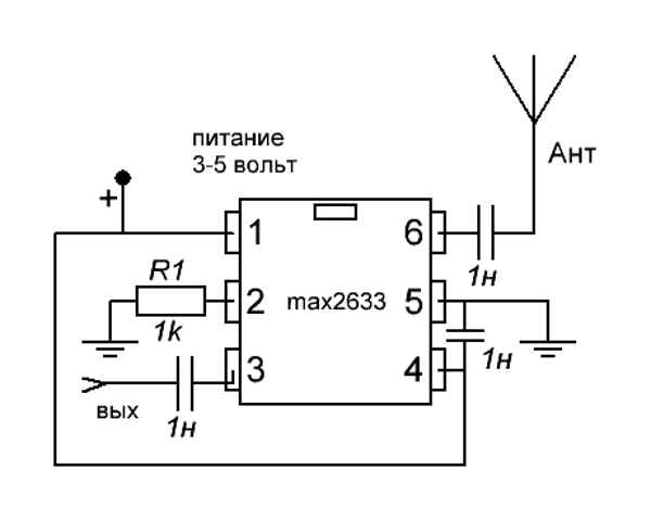
You can design a simple device that amplifies your TV signal for your TV with your own hands. Such a device has low power consumption, does not create significant interference, and has frequency range up to 900 MHz. The low-voltage amplifier powered by 2.7-5.5 V consumes 3 mA and is very quiet.
Various factors can negatively affect the TV signal level. Modern radio technology devices help to increase it. They have a number of advantages: mobility, high gain and great choice models. Thanks to joint work antenna and amplifier, you can watch TV in good quality.
The best TVs of 2018 according to buyers
TV LG 43UJ634V
TV Samsung UE50MU6100U
TV Hyundai H-LED24F402BS2
TV LG 22LH450V
TV Samsung UE22H5600