A simple do-it-yourself inverter from an uninterruptible power supply. Charger in a hurry from a burnt uninterruptible power supply How to make a power supply unit from an uninterruptible power supply
Almost for free I bought myself a 350W uninterruptible power supply from a computer. I always wanted to make a powerful 10A 12V power supply from it, all the same, the transformer is more reliable than the impulse switch. When the opportunity presents itself, why not take advantage of it?
The assembly process took about five hours, and the entire assembly lasted two months. I bought an uninterruptible power supply two months ago.
The first step was to remove the transformer. And the resistance of the network windings was checked. The black wire is the beginning of the winding, the blue wire is the end of the winding, the red wire is the outlet. 

When I decided on the network winding, I decided to supply power between black and red, then the output power will be slightly higher, and the no-load current will be higher. Naturally, this will lead to additional heating of the windings, but I will have forced cooling.
Having considered all possible options for the future power supply, I ordered the necessary components from China and, in order not to waste time, prepared the case. I moved the transformer from its original place and fixed it to the bottom with four M4 screws, where the trance stood. installed a radiator for the future diode bridge. I also cut a hole for the fan in the back of the case.  Somewhere in a month, a pulse-down converter came to XL4016 12A 0-32V, here is a link to it. Che, I stopped to take a photo before reworking the converter, so I'll explain what I did.

Instead of native tuning resistors, Soviet resistors were installed. For the voltage regulator, the resistor is set to 4.7 kOhm, I will bring it out with two wires to front panel. This rating makes it possible to regulate the voltage in the range of 1.2V-18.5V. For the current regulator, I installed a variable resistor of 1 kOhm, added a 25 kOhm resistor along the positive wire, which makes it possible to regulate the current within 0-10A.
Also, instead of the block, I soldered wires, wires 0.75 mm square. twisted in pairs to increase the cross section.
A month later, literally yesterday, the rest of the components arrived and I set to work. There are no photos of the process again, so I'll go through the finished device.
Two regulators were displayed on the front panel: current and voltage. Installed ammeter type 91C4 10A, electronic voltmeter and terminal blocks left over from the previous one. I also removed the voltage stabilization indicator LED from the board. 

In the rear part, an XL4016 converter board is installed on the partition, a KBPC5010 diode bridge was installed on the radiator, and a 35V 4700 uF capacitor was glued to the case. A capacitor is needed for filtering mains voltage, after the bridge with it, a voltage of 22V was obtained.
To power the fan and voltmeter, I used an additional winding from the transformer, installed a diode bridge with a 2200 uF capacitor. After the 25V diode bridge, this voltage is suitable for powering a voltmeter, but there is a lot of this for powering a fan, so the fan will be powered through two 470 Ohm 2 W resistors in parallel. The bridge with the capacitor was fixed with a canopy.
By the way, to protect against all sorts of cases, I installed a fuse on the side panel. 
 This whole assembly took only 5 hours, we can say that everything was assembled in the evening.
Now it's time to move on to testing this device, well, first I'll look at how accurate the voltmeter is.
I chose the main voltages as for charging different Batteries, the first will be the voltage for LI-ION 4.18 V. The voltmeter showed 4.16 V, which is quite normal for a Chinese voltmeter. 
I chose the next voltage for three lithium batteries, here the voltmeter showed 0.1V more, which is also not so scary.  The last voltage is 14.4V for lead batteries. Also an error of 0.1 V, but again it is acceptable.
 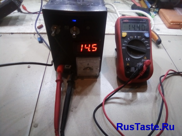 Well, I'll check the ammeter, although it pleased me much more than the voltmeter.
  Enough messing around, it's time to load up. What will happen to the block if there is a short circuit?
  Well, now I’ll load everything with nichrome, it turned out to load 6A at 15 V
 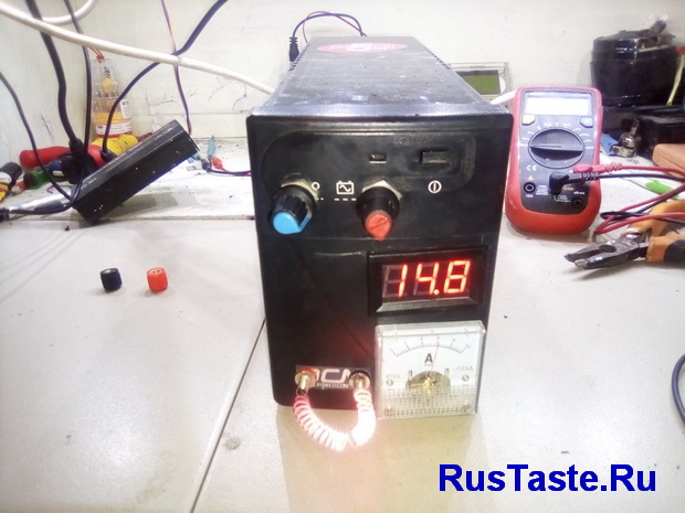 I will not load for a long time, because I will melt the case. But for about 10 minutes everything warmed up without problems for the case
The last thing left to do for this power supply is to connect the wires with the terminals. I bought such a wire once for 300 rubles.  This completes the assembly and the last thing I need to do is draw a power supply circuit for you
And also add links to all used components
Converter on XL4016 12A 30V worth 290 rubles
Diode bridge 50A 1000V for 100 rubles
Voltmeter 100V for 60 rubles
Ammeter 10A for 130 rubles
Terminal block 4 pieces for 100 rubles
Considering that the uninterruptible power supply itself cost 500 rubles, plus additional parts and so on, my power supply unit from an uninterruptible power supply cost me 1,500 rubles
Well, that’s all for now, if you like my homemade products and don’t want to miss new ones, subscribe to updates in In contact with or Odnoklassniki
Do not want to delve into the routine of radio electronics? I recommend paying attention to the proposals of our Chinese friends. For a very reasonable price, you can buy pretty high-quality chargers
Simple charger with LED charging indicator, green battery is charging, red battery is charged.
There is protection from short circuit, there is protection against polarity reversal. Perfect for charging Moto batteries with a capacity of up to 20A\h, a 9A\h battery will charge in 7 hours, 20A\h in 16 hours. Price for this charger 403 rubles, delivery is free

This type of charger is able to automatically charge almost any type of car and motorcycle batteries 12V up to 80Ah. Has a unique three-step charging method: 1. Charging direct current, 2. Constant voltage charging, 3. Drip recharge up to 100%.
There are two indicators on the front panel, the first indicates the voltage and percentage of charge, the second indicates the charging current.
Pretty high-quality device for home use, the price of everything 781.96 rubles, delivery is free. At the time of this writing number of orders 1392, grade 4.8 out of 5. When ordering, do not forget to specify europlug
Uninterruptable power source - irreplaceable thing. Moreover, it and its components can be used in very different ways. From the old uninterruptible power supply or its parts, you can easily get:
- inverter;
- Charger;
- power unit.
As for the power supply, using an old uninterruptible power supply you can make both a simple block and a laboratory one. Naturally, a laboratory power supply is much more difficult to assemble, install, install and configure, and will also require more additional parts and tools. However, they are based on the same principle, and the same problems arise when using them.
Let's first consider simple block power supply and schemes for its manufacture from an old UPS from a computer.What will be required?
To make a simple do-it-yourself power supply from an uninterruptible power supply will be required:
- transformer from uninterruptible power supply;
- case - fit and old building from the UPS, and self-made to create a power supply;
- diode bridge.
When performing work, it is necessary to have basic knowledge in physics and electromechanics, as well as observe safety regulations, use protective clothing and use dielectrics.
When it comes to a simple power supply, most are faced with the same difficulty: the outputs from standard transformers are typically 15 V.
When a load is connected to the resulting power supply, it “sags”, so that the desired voltage is selected experimentally.Step-by-step algorithm of actions
Action algorithm for self-production of a power supply from an old UPS will be as follows:
- the transformer is disconnected from the UPS, the future case of the device is being prepared;
- using an ohmmeter, the winding with the highest resistance value is determined: black and white wires, which in the future will serve as an input to the device (if the old case from the UPS is used for manufacturing, then the input will be the corresponding socket located at the end of the uninterruptible power supply and serving for connection of the device and socket);
- from the wires located on one side of the location of the core, an "input" is formed, from the wires located on the opposite side, the "output" of the device is equipped;
- supplied to the transformer alternating current with a voltage of 220 volts;
- voltage is removed from unused contacts;
- a pair is determined that has a potential difference of 15 volts (white and yellow wires - “output”);
- a diode bridge is installed on the "output";
- consumers are connected to its contacts.
The main purpose of uninterruptible power supplies (UPS) is a short supply of various office equipment (primarily computers) in emergency situations when there is no mains voltage. The UPS consists of a battery (usually 12 V), a step-up voltage converter, and a control unit. In standby mode, the battery is recharged, in emergency mode, the voltage converter is turned on.
Like all equipment, UPSs fail or become obsolete. Therefore, they can be used as a basis for the manufacture, for example, of a laboratory power supply unit (PSU). The most suitable for this may be UPS, in which voltage converters operate at low frequency (50 ... 60 Hz), and they include a powerful step-up transformer, which can also work as a step-down transformer.
For the manufacture of a laboratory PSU, the KIN-325A UPS was used as a "donor". During development, the task was to obtain a simple circuit, while applying as many elements from the "donor" as possible. In addition to the transformer and case, powerful field-effect transistors, rectifier diodes, a quad op-amp microcircuit, an electromagnetic relay, all LEDs, a varistor, some connectors, as well as oxide and ceramic capacitors were used.
The power supply circuit is shown in fig. 1. The mains voltage through the fuse-link FU1 and the power switch SA1 is supplied to the primary winding of the transformer T1 (marking - RT-425B). The varistor RU1, connected in parallel with this winding, together with the fusible link, protect the PSU from increased mains voltage. Through the current-limiting resistor R1 and the diode VD1, the HL1 LED is powered, indicating the presence of mains voltage.
A powerful rectifier on diode assemblies VD2-VD5 is connected to winding II (with a tap in the middle, rated voltage 16 V) of transformer T1. Depending on the position of the contacts of relay K1.1, the rectifier operates as a full-wave rectifier with a common transformer output (shown in Fig. 1) and an output voltage of about 10 V or as a bridge with an output voltage of about 20 V. The output voltage of this rectifier is supplied to the control element - field-effect transistor
VT1. Capacitors C1 and C3 smooth out the ripple of the rectified voltage, resistor R2 is a current sensor. Resistor R17 provides a minimum voltage regulator load in the absence of an external load.
Low Power Rectifier assembled on diodes VD6-VD9 and smoothing capacitors C2 and C5. It is powered by a parallel voltage regulator on the DA1 chip, op-amp DA2, relay K1 and fan M1. The HL2 LED indicates the presence of voltage at the output of this rectifier.
The adjustable voltage regulator is assembled on the op-amp DA2.3 and the transistor VT1. The exemplary voltage to the voltage regulator - resistor R11 - comes from the output of the stabilizer on the DA1 chip. The output voltage of the PSU from the trimmer resistor R12 is fed to the inverting input of the op amp DA2.3. This resistor sets the maximum output voltage. The adjustable current limiter is assembled on the op-amp DA2.1 and DA2.2. A voltage proportional to the output current from the sensor - resistor R2, is supplied to the voltage amplifier at the op-amp DA2.1 and then to the op-amp DA2.2, which compares it with the exemplary one supplied to its non-inverting input from the output resistive divider R4R7R8. Resistors R7 and R8 set the current limit threshold.
Transistor VT2 controls relay K1. It will work when the voltage at the gate of this transistor exceeds the threshold value (for the transistor indicated on the diagram, the threshold voltage is 2 ... 4 V). The trimmer resistor R19 sets the output voltage of the PSU, above which the relay switches the output voltage of the rectifier. Transistor VT3 together with thermistor RK1 controls fan M1. It turns on when the temperature of the heat sink, on which the transistor VT1 and the thermistor are installed, exceeds a predetermined value. The threshold temperature is set by resistor R15. The supply voltage of the thermistor is stabilized by a parametric stabilizer VD11R16. The excess supply voltage of relay K1 drops across resistor R13, and fan M1 drops across resistor R18.
If the load current does not exceed the threshold value, the voltage at the non-inverting input of the op-amp DA2.2 is greater than the voltage at the inverting one, at its output there is a voltage close to the supply voltage, so the VD10 diode is closed, and the current does not flow through the HL3 LED. In this case, the control voltage to the gate of the field-effect transistor VT1 comes from the output of the op-amp DA2.3 through the resistor R14 and the voltage regulator works. If the output voltage of the stabilizer is less than 4 V, the transistor VT2 is closed and relay K1 is de-energized. In this case, the voltage at the drain of transistor VT1 is 10 V. When the output voltage is more than 4 V, transistor VT2 opens and relay K1 is activated. As a result, the voltage at the drain of the transistor VT1 rises to 20 V. This technical solution improves the efficiency of the device.
When the load current exceeds the threshold value, the voltage at the output of the op amp DA2.2 will decrease, the diode VD10 will open and the gate voltage of the transistor VT1 will decrease to a value that ensures the flow of the set current. In this mode, current flows through the HL3 LED, and it signals the transition to the current limiting mode. The limiting current is set by resistor R8 in the range of 0 ... 0.5 A and R7 - in the range of 0 ... 5 A. Capacitors C4 and C6 ensure the stability of the current limiter. Increasing their capacitance increases stability, but reduces the speed of the current limiter.
The device uses fixed resistors - C2-23, R1-4 or imported, tuning - SP3-19, variables - SP4-1, SPO. In order for the scale of variable resistors that regulate voltage or current to be linear, they must be of group A. Thermistor - MMT-1. Resistor R2 is made from a piece of wire PEV-2 0.4 150 mm long. In addition to the function of a current sensor, it also works as a fuse in case of emergency. Oxide capacitors are imported, ceramic K10-17 can be used in place of non-polar ones. The fan is a computer fan with a consumption current of 100 ... 150 mA, its width must be equal to the width of the heat sink. Relay - any, designed for a switched current of 10 A and a rated voltage of the winding of 12 ... 15 V. XS2, XS3 - sockets or terminal blocks.
Most of the elements are placed on two printed circuit boards made of fiberglass laminated on one side with a thickness of 1.5 ... 2 mm. On the first one (Fig. 2), rectifiers are assembled, transistors VT2, VT3 are mounted with elements "surrounding" them, and some other details. The printed conductors connecting the elements of a powerful rectifier are "reinforced" - pieces of tinned metal are soldered to them. copper wire 1 mm in diameter. The "regular" outputs of the T1 transformer are wired, they are equipped with two sockets. If you plan to use them, the plugs corresponding to them are mounted on the first board, which are soldered from the "native" UPS board.

On the second board (Fig. 3) all microcircuits, LEDs, as well as some other elements are mounted. On the side free of printed conductors, a push-button switch SA1 (P2K or similar) is glued. The LEDs should go into the "regular" holes on the front wall of the case, a "regular" pusher is glued to the switch.
The first board is installed next to the rear wall of the case, the second - close to the front. To fasten the boards, two screws and "regular" fixing plastic racks on the top cover of the case were used. On a finned heat sink with external dimensions 30x60x90 mm (it is installed between the boards) placed transistor VT1, thermistor and fan. A heat-shrinkable tube is put on the thermistor and then glued to the heat sink next to the transistor. Since the field-effect transistor VT3 opens and closes smoothly when the temperature of the thermistor changes, the fan starts rotating and stops also smoothly. Therefore, the VT3 transistor can noticeably warm up and it is impossible to replace it with a low-power one, for example, 2N7000.
On the front panel (Fig. 4), variable resistors and connectors XS2 and XS3 are installed in the holes, to which resistor R17 and capacitor C7 are soldered. Block plug XP1 and socket XS1 are "native", they are located on the rear wall in its lower part. The XS1 socket can be used to connect any device that works simultaneously with a laboratory PSU, such as an oscilloscope.

The adjustment begins with setting the maximum output voltage. This is done using the resistor R12, while the slider of the resistor R11 should be in the upper position according to the diagram. If it is not planned to build a voltmeter into the power supply, the resistor R11 is provided with a pen with a pointer and its scale is graduated. When transistor VT2 is open, by selecting resistor R13, the nominal voltage is set to relay K1, and when VT3 is open, resistor R18 is set to 12 V on fan M1. The fan switch-on temperature is set by resistor R15.
To establish a current limiter, an ammeter and a load variable resistor with a resistance of 10 ... 15 Ohms and a power of 50 W are connected in series to the PSU output. The sliders of resistors R4 and R7 are set to the left position according to the diagram, the slider R8 is set to the right. The load resistor must have the maximum resistance. With an output voltage of about 10 V, a load resistor sets a current of 5 A, and a resistor R5 sets a voltage of 0.9 ... 1 V at the output of the op-amp DA2.1. With the help of a load resistor, the output load current is increased to 6 A and, by smoothly rotating the slider of the resistor R4, the HL3 LED is turned on (turning on the current limiting mode) and then the output current is set to 5 A by the resistor R4. When the slider of the resistor R7 is moved to the right (according to the circuit), the output current should drop to zero. In this case, resistor R8 can regulate the output current in the range of 0 ... 0.5 A.
If you do not plan to build an ammeter into the power supply, the scales of these resistors are graduated. To do this (in the current limiting mode), the output voltage and load resistance are changed, the required current value is set, and marks are applied to the scale. In this case, in the range of 0 ... 0.5 A, the current is set by resistor R8 (resistor R7 must be in position "0"), and in the range of 0 ... 5 A - by resistor R7 (resistor R8 - in position "0") .
In current limiting mode, batteries and rechargeable batteries can be charged. To do this, set the final voltage and charging current, and then connect battery(battery).
Further improvement of the proposed power supply is the installation of a built-in digital voltmeter, ammeter or combined measuring device.
Publication date:
12.12.2014Readers' opinions
- zluka / 23.01.2017 - 00:07
There, the overall size of the trance is ~ 60 W, as in the RT-525 and RT-W06BN, and even 5A is an overload, optimally - 4A. Another thing is 430-9102, you can remove 25-30A from it. Yes, and there will not be (20-12)x5, drawdown at a load of 5A - up to 14v and below. - Beginner / 05.03.2016 - 15:03
A simple circuit, but at a maximum load of 5A, 12x5 \u003d 60 W will go into the load, and (20-12) x5 \u003d 40 W will be dissipated on the control transistor. Is there a way to "squeeze" more out of the UPS?
Front panel of the unit
Back panel

The transformer itself

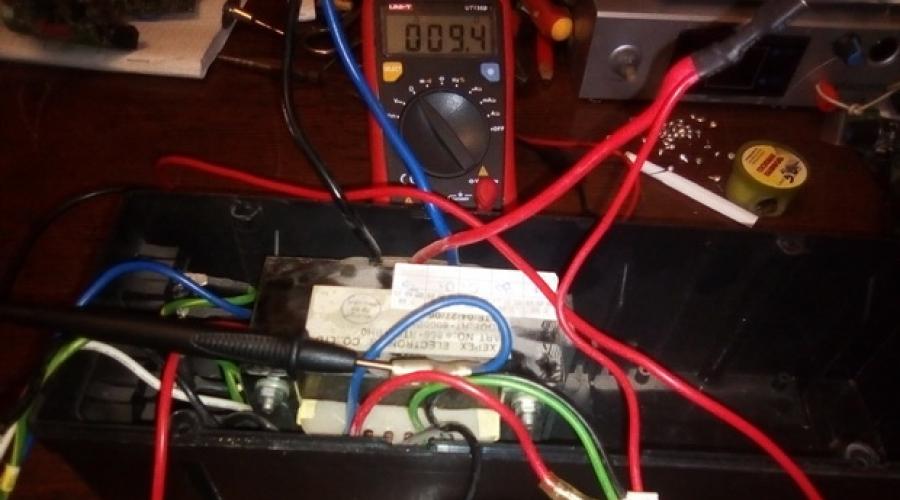
Its dimensions are 100 X 80 X 80 mm. Weight 2.2 kg. On inspection, no visible damage was found. One winding is visible under the insulation, a fairly thick wire of about 1.5 square meters. mm maybe thicker. I found the winding with the highest resistance in this transformer, it turned out to be 12.6 Ohm. The color of the wires is white + black, on one side of the core. I applied 220 V to them for a short time - nothing - no hum, no smoke - it's already good. I found a secondary on the other side of the iron with a maximum voltage of about 15 V. The color of the wires is white + yellow.

I had a 50 A diode bridge. I connected it through my native connectors, this is clearly visible in the figure. Then I connected a 12 Volt 35 Watt halogen lamp to the diode bridge.

The voltage under load dropped to 13 volts. The voltage at the output of the diode bridge is 14 V, without load.

Current under load - 3.3 Amps. The lamp was on for about an hour. After that, I checked the temperature of the transformer winding with my hand - it was completely cold. I think he will pull more current, but it was already too lazy to check. So it is quite possible to make quite powerful and high-quality power supplies or chargers from uninterruptible transformers. Author: Volodya (skrl)
Before every car owner someday the question arises of how to charge a dead battery. He appeared in front of me once too. And it happened, as always, unexpectedly, on a day off, in the village, and as luck would have it, no one nearby found anything resembling exercise. I had to strain my brains and quickly make a simple but powerful charger from improvised means. And the burnt UPS helped me in this - an uninterruptible power supply for computers. Without going into deep details, I'll just note that this device powers the computer from the built-in 12-volt battery when the power goes out.
The most important thing is taken from a broken uninterruptible power supply - a powerful transformer, which usually remains intact, we do not need all the other spare parts from it.

So, to make a simple charger you will need:
1. Transformer from a burned-out uninterruptible power supply
2. Diode bridge (rectifier) 2-4 pcs.
3. Capacitor 100 ... 1000 microfarads with a voltage of at least 25 V
4. Medium size radiator
5. Plank, plywood, plastic
6. Thermal grease KPT-8
7. Tester
8. Soldering iron, pieces of wire


Using a tester, we determine the terminals of the winding, which have a greater resistance (from 10 to 50 Ohms), this will be a 220 V network winding. Conclusions secondary winding 12V thicker, it is wound with a thicker wire, so the resistance of the secondary winding is almost zero.
The conclusions that went to the output connectors of the uninterruptible power supply will now be connected to the network, and the wires through which 12V was supplied from the board will be connected to the rectifier.
You will also need several rectifier diode bridges GBU406, GBU 605, GBU606, and a filter capacitance, a capacitor from 100 to 1000 microfarads for a voltage of at least 25V (from a burned-out computer power supply). A small heatsink for the diodes will also come in handy. Of course, you can make a rectifier on ordinary diodes with a maximum current of at least 10 A and reverse voltage at least 25 V, but at that moment they were not at hand, and later I also used ready-made rectifier bridges, because it is convenient to mount them on a radiator. Rectifier bridges are stacked, smeared with heat-conducting paste and pressed against the radiator with a long bolt. All pins of the same name are connected in parallel. Pluses with pluses, minuses with minuses, etc.

A transformer, a radiator with diodes are attached to a suitable wooden board, plywood, or a piece of plastic, the entire circuit is mounted, a cord with a plug from an old soldering iron is connected - and charging is ready!
Mounting options and layout of the charger nodes can be any, based on what is at hand.


With a rectified output voltage of about 18 V, the charger freely gives a current of up to 5 A. A conventional battery is charged in an hour, a strongly planted one in 3 ... 4 hours. Many motorists in our village now have such charging.
Moreover, for a better charge of the batteries, I came up with the idea of connecting the charger in a pulsed mode. Pulse, of course, is said loudly, it only means that it is connected to the outlet through an electromechanical time relay.
This is a simple daily electromechanical relay, it comes from China, they sell in the store for 150 rubles.