Homemade GPS tracker on Arduino. The best GPS trackers for cars (beacons)
Read also
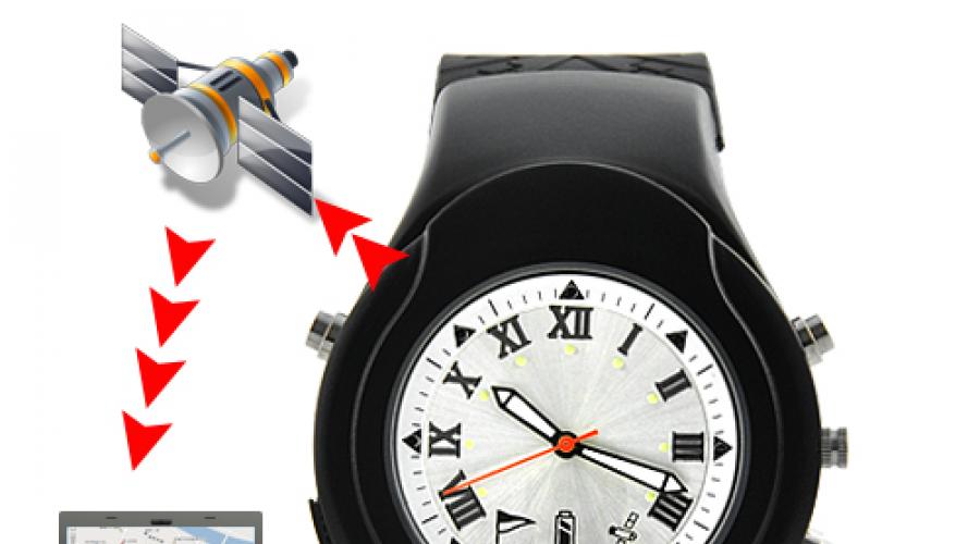
Personal GPS transmitters
Today, progress is proceeding at such a pace that devices that were previously bulky, expensive and highly specialized are quickly losing size, weight and price, but gaining many new functions.
 This is how devices based on GPS technology reached pocket gadgets and firmly settled there, giving people new opportunities. It is especially worth highlighting individual GPS transmitters.
Essentially, these are the same GPS trackers, only designed for use not on a vehicle, but by a person in everyday life.
 Depending on the model, several various devices. In the simplest version, it’s just a small box without a display, which allows you to control the movements of children, animals or some other objects, on which it is fixed.
Inside it there is a GPS module that determines coordinates on the ground, a GSM/GPRS module that transmits information and receives control commands, as well as a power source that provides autonomous operation During a long time.
Functionality of GPS transmitters
As the functionality increases, the following capabilities of the device appear:

Options for GPS transmitters
 Depending on the configuration, transmitter housings may differ significantly. Various models are available in the form cell phones, classic navigators, or even wristwatches.
Colorful design of special versions and useful additions allow children to treat these devices not as “parental spies”, but as fashionable and practical gadgets.
 As an advantage, it is worth mentioning the fact that many versions of the device can do without subscription fee for the services of specialized operators, and all the necessary information is sent to the client directly via the Internet or SMS messages, which allows significant savings on the maintenance of such equipment.
Articles about GPS trackers
In this article I will show how to use a gsm module with arduino using the sim800L as an example. The same instructions are quite suitable for using any other gsm modules, for example, sim900, etc., because all modules work in approximately the same way - this is the exchange of AT commands through the port.
I will show the use of the module with arduino using the example of an SMS relay, which can be used to control the device remotely via SMS commands. This can be used in conjunction with car alarms, etc.
The module is connected to Arduino via the UART interface of the software serial port, operating on 2 and 3 digital outputs Arduino nano.
Working with Arduino with GSM modules
To power the module, a voltage in the range from 3.6V to 4.2V is required, this means that you will have to use an additional voltage stabilizer, since the Arduino has a 3.3 volt stabilizer installed, which is not suitable for powering the module, the second reason to install an additional stabilizer is that the GSM module is serious load, since it has a weak transmitter that provides stable communication with the cellular station. Power for the Arduino nano is supplied to the VIN pin - this is a stabilizer built into the Arduino that ensures the module operates over a wide voltage range (6-10V). The relay module is connected according to the given program text to pin 10 of the Arduino nano and can easily be changed to any other that works as a digital output.
It works like this: install a SIM card in the GSM module, turn on the power and send an SMS with the text “1” to the number SIM cards in order to turn on our relay, to turn it off we send an SMS with the text “0”.
#include
SoftwareSerial gprsSerial(2, 3); // set pins 2 and 3 for software port
int LedPin = 10; // for relay
void setup()
{
gprsSerial.begin(4800);
pinMode(LedPin, OUTPUT);
// setting up message reception
gprsSerial.print("AT+CMGF=1\r");
gprsSerial.print("AT+IFC=1, 1\r");
delay(500);
gprsSerial.print("AT+CPBS=\"SM\"\r");
delay(500); // delay for command processing
gprsSerial.print("AT+CNMI=1,2,2,1,0\r");
delay(700);
}
String currStr = "";
// if this line is a message, then the variable will take the value True
boolean isStringMessage = false;
void loop()
{
if (!gprsSerial.available())
return;
char currSymb = gprsSerial.read();
if ('\r' == currSymb) (
if (isStringMessage) (
// if the current line is a message, then...
if (!currStr.compareTo("1")) (
digitalWrite(LedPin, HIGH);
) else if (!currStr.compareTo("0")) (
digitalWrite(LedPin, LOW);
}
isStringMessage = false;
) else (
if (currStr.startsWith("+CMT")) (
// if the current line begins with “+CMT”, then the next message
isStringMessage = true;
}
}
currStr = "";
) else if (‘\n’ != currSymb) (
currStr += String(currSymb);
}
}
Video version of the article:
Tags: #Arduino, #SIM800L
Your mark:
Products used in this article:
← GPS logger on arduino | Relay control via COM port →
GSM scanner on RTL-SDR
| home| English | Development | FAQ |
Main characteristics of the scanner
The GSM scanner scans downstream GSM channels and displays information about the signal level and whether the channel belongs to one of the three main cellular operators MTS, Beeline and Megafon. Based on the results of its work, the scanner allows you to save a list of identifiers base stations MCC, MNC, LAC and CI for all scanned channels.
A GSM scanner can be used to evaluate the GSM signal level and compare signal quality different operators, radio coverage assessments, when deciding on installing cellular signal amplifiers and adjusting their parameters, for educational purposes, etc.
The scanner runs under Windows and uses a simple and cheap receiver - RTL-SDR. You can read about RTL-SDR at:
RTL-SDR (RTL2832U) and software defined radio news and projects,
RTL-SDR – OsmoSDR,
RTL-SDR in Russian.
The RTL-SDR parameters determine the main characteristics of the scanner. Of course, a GSM scanner is not a replacement for normal measuring equipment.
The scanner is distributed free of charge, without any restrictions on use.
Current version supports the GSM 900 band and does not support GSM 1800. This is determined by the fact that the operating frequency of the RTL-SDR with the R820T tuner is limited to 1760 MHz. There is hope that the use of the experimental RTL-SDR driver will allow operation in at least part of the 1800 MHz range.
Starting the scanner
The latest version of the scanner can be downloaded from this link. Simply unzip the file to a convenient location and run gsmscan.exe.
Previous versions of the scanner, a link to the repository with sources and other information related to the development are located on the development page.
For the scanner to operate, the installation of RTL-SDR drivers is required; if they have not already been installed, this can be conveniently done using the Zadig program to describe the installation procedure.
Using the Scanner
Below is a view of the scanner program window:

The horizontal axis displays the GSM channel number in the form ARFCN or in MHz, according to vertical axis signal level in dBm. The height of the line shows the signal strength.
GSM module NEOWAY M590 communication with Arduino
If the BS identifiers have been decoded successfully and they correspond to the identifiers of the three major telecom operators, the lines are painted in the corresponding colors.
The drop-down lists at the top of the screen allow you to select the SDR receiver, if several are connected, the operating range GSM 900 or GSM 1800 and the units of measurement along the horizontal axis ARFCN or MHz.
The buttons allow you to save a report on the scanner’s operation in the form of a list of decoded base stations, clear the results of BS decoding and obtain information about the program.
Principles and features of work.
During operation, the program scans the operating frequency range with a step of 2.0 MHz (10 GSM channels) and digitizes the signal with a sampling frequency of 2.4 MHz. The scanning process consists of a fast pass through the entire range to measure signal strength and a slow pass to decode the BS identifiers.
One decoding step is performed after traversing the entire range to measure power. Thus, in the GSM 900 range, the signal level is updated approximately once every 2 s, and a complete decoding pass takes about 1 minute.
Due to the poor quality of the signal received from RTL-SDR, the probability of correctly decoding system information (SI) of the BS broadcast control channel (BCCH) is not high. Signal level fluctuations as a result of multipath propagation also reduce the likelihood of decoding system information. For these reasons, to obtain BS identifiers, it is necessary for the scanner to accumulate information over a period of about 10 minutes. But even in this case, not all channels provide this place sufficient signal level and quality for decoding even by the most ideal receiver. In addition, not all GSM channels are used to work according to the GSM standard, as can be seen in the figure above, channels 975 - 1000 are occupied by Megafon to work according to the UMTS standard.
During operation, the scanner adds system information about new decoded channels to the general array of information on channels. But information about previously decoded channels is not erased when system information is not decoded at this step, and remains in the array. To clear this information, use the button to clear the BS decoding results.
When you click on the save report button, the accumulated results are saved in text file with a name made up of the name of the program, the date and time the data was saved. Below is an example of part of the report file:
The scanner is designed to work under Windows 7, 8.1 and 10. The work was tested with three copies of the RTL-SDR with the R820T tuner; other types of tuners were not tested.
A special version of the program has been compiled to work under Windows XP; it runs several times slower than the standard version.
Development.
The scanner program is supplied as is, without any warranties or liability. If you have reasonable ideas on how to expand the functionality or improve the performance of the scanner, we are ready to discuss the possibility of their implementation.
You can take part in the development of the scanner; to do this, visit the development page.
Further development of the GSM scanner is planned, possibly with your participation.
Do you need an accurate time source from GPS? This article will show you how to use a GPS module to get time, date and coordinates, and how to display them on an LCD using Arduino.
What is necessary?
- computer with Arduino IDE installed;
- Arduino (we use Arduino Mega);
- GPS module (we use EM-411, others are possible that support NMEA protocol, for example, VK2828U7G5LF or GY-NEO6MV2);
- breadboard, jumpers and 5 kOhm potentiometer;
- TinyGPS library (link below).
Introduction
The development of the global positioning system, or GPS, began in the early 1970s. Each country (Russia, USA, China, etc.) has its own system, but most satellite navigation facilities in the world use the US system.
Each satellite in the system has an atomic clock that is continuously monitored and adjusted by NORAD (North American Aerospace Defense Command) every day.
Essentially, the receiver uses its clock to measure the TOA (time of arrival) of four satellite signals. Based on TOA and TOT (time of transmission), the receiver calculates four values of time of flight (TOF), which differ from each other depending on the distance from the satellite to the receiver. Then, from the four TOF values, the receiver calculates its position in 3D space and the deviation of its clock.
The most inexpensive GPS receivers have an accuracy of about 20 meters for most places on Earth. Now let's see how to make your own GPS clock using Arduino.
Hardware
My GPS module has 6 pins: GND, Vin, Tx, Rx and GND again. The sixth pin is not connected anywhere. The GND pin is connected to the case on the Arduino, Vin is connected to the +5V bus on the Arduino, Tx is connected to pin 10 on the Arduino, and the Rx pin is not connected anywhere, since we will not send any messages to the GPS module. My module transmits satellite data using the RS-232 interface at 4800 bps, which is received by the Arduino on pin 10.
Below is a photo of the GPS module:
GPS module EM-411
The module sends what are known as NMEA messages. Here you can see an example of one NMEA message and its explanation (excerpt from technical description):
$GPGGA,161229.487,3723.2475,N,12158.3416,W,1.07,1.0,9.0,M,0000*18
| Name | Example | Units | Description |
|---|---|---|---|
| Message ID | $GPGGA | GGA protocol header | |
| UTC time | 161229.487 | hhmmss.sss (two digit hours, two digit minutes, then seconds to the thousandths) | |
| Latitude | 3723.2475 | ||
| N/S flag | N | N - north, S - south | |
| Longitude | 12158.3416 | ddmm.mmmm (the first two digits are degrees, then minutes to the nearest ten thousandths) | |
| E/W flag | W | E - east, W - west | |
| Location indicator | 1 |
|
|
| Number of satellites used | 07 | Ranges from 0 to 12 | |
| HDOP | 1.0 | Deterioration of horizontal accuracy | |
| Height relative to sea level | 9.0 | meters | |
| Units | M | meters | |
| Geoidal difference | Difference between WGS-84 earth ellipsoid and sea level (genoid) | ||
| Units | M | meters | |
| Age of differential GPS data | seconds | Null fields when DGPS is not used | |
| ID of the station transmitting differential corrections | 0000 | ||
| Check sum | *18 | ||
| End of message |
All this data is received by the Arduino via pin 10. The TinyGPS library reads GPGGA and GPRMC messages (for detailed information about GPRMC see technical description).
Arduino is not shown in the diagram. Connect peripherals according to signed connections.
 Scheme GPS watch on arduino
 Software
When power is applied, the GPS module takes some time to obtain the correct location from the satellites. When a location is received, the module sends NMEA messages to the Arduino. The TinyGPS library contains a function to get the time and date from a GPRMC message. It's called crack_datetime() and takes seven pointers to variables as parameters: year year , month month , day of month day , hour hour , minutes minute , seconds second , and hundredths of a second hundredths . The function call looks like this:
GPS.crack_datetime(&year, &month, &day, &hour, &minute, &second, &hundredths);
Calling this function returns you the correct values in the variables as long as everything is in order with the hardware.
To get your location, you can call the f_get_position() function. This function takes as parameters two pointers to variables: latitude latitude and longitude longitude . Calling this function looks like this:
Gps.f_get_position(&latitude, &longitude);
Source text of the program:
#include
Today we will make a GPS Tracker based on Arduino MKR FOX 1200 that sends accurate GPS data via Sigfox network.
This is becoming even more relevant for many countries due to increased control over any imported technical devices, especially those related to GPS.
Step 1. What we will need
The set of parts for this lesson is not large:
- Arduino MKR Fox 1200 × 1
- GPS module (optional, but we used a replica of ublox NEO6m (ATGM332D) × 1
- General purpose NPN transistor (we used BC548) × 1
- Resistor 1 kOhm × 1
Step 2. Project information
The tracker uses the ATGM332 GPS module to obtain GPS position with greater accuracy than the location services provided by Sigfox. The item data is then sent as a "string" through the Sigfox network and finally delivered via email.
![]()
Arduino MKR FOX 1200
The board is similar to the Arduino Zero, which is based on the SAM D21 and includes an ATA8520 Sigfox module. This is a low-power board that comes with the board with a free one-year subscription to the Sigfox network (up to 140 messages per day), as well as free access to the location service Spot"it.
GPS module ATGM332
This low-cost, low-power GPS module fits the Arduino MKR FOX 1200 very well as it only works with 2.7V (nominal 3.3V).
Initially I was supposed to buy the NEO6m2 module, which has a standby mode, but I had to use NEO6. In fact it was an ATGM332 module. As a result, it had no standby mode, so it was necessary to use a transistor to turn the GPS module on when needed and turn it off to save battery. Our goal is to have location information quite infrequently, i.e. 4 messages per hour, since Sigfox only allows 140 messages per day.
We use the TinyGPS library (https://github.com/mikalhart/TinyGPS) to decode GPS frames.
Transistor switch
It was necessary to turn GPS on and off when necessary. Relay modules are too bulky and powerful if you only need to switch a 3V load and a few milliamps. Also, most relay modules require 5V. So a transistor would be a better solution. Additionally, the MKR FOX 1200 only provides 7 mA on the I/O pin.
A BC548 NPN transistor will do. When the zero signal is applied to the base of the transistor, it turns off, acting like an open switch, and no collector current flows. When a positive signal is applied to the base of the transistor, it becomes "on", acting as a closed switch, and maximum circuit current flows through the device.
Step 3. Connection diagram

The only power source is two 1.5V AA batteries that power the Arduino MKR FOX 1200. The GPS module receives power from the Arduino board.
The Arduino MKR FOX 1200 communicates with the GPS module using the second serial port via pins 13 and 14, called Serial1 in the code. The TX data output of the GPS module is connected to the serial data input (pin 13) of the Arduino board.
Additionally, the Arduino board uses PIN2 to turn the GPS module on and off, as explained above.
Step 4. Project code
You can download or copy the code of our project below:
#include// Start the module SigFox.begin();
// Wait at least 30mS after first configuration (100mS before) delay(100);
// Clears all pending interrupts SigFox.status();
delay(1);
if (debug) SigFox.debug();
- delay(100);
- SigFox.beginPacket();
- SigFox.print(data);
if (debug) ( int ret = SigFox.endPacket(true); // send buffer to SIGFOX network and wait for a response if (ret > 0) ( Serial.println("No transmission"); ) else ( Serial.println ("Transmission ok"); ) Serial.println(SigFox.status(SIGFOX)); if (SigFox.parsePacket()) ( Serial.println("Response from server: "); while (SigFox.available()) ( Serial.print("0x"); Serial.println(SigFox.read(), HEX); ) ) else ( Serial.println("Could not get any response from the server"); Serial.println("Check the SigFox coverage in your area"); Serial.println("If you are indoor, check the 20dB coverage or move near a window"); ) Serial.println(); ) else ( SigFox.endPacket(); ) SigFox.end(); ) ////////////////// Convert GPS function ////////////////// /* Converts GPS float data to Char data * / String ConvertGPSdata(const void* data, uint8_t len) ( uint8_t* bytes = (uint8_t*)data; String cadena ; if (debug) ( Serial.print("Length: "); Serial.println(len); ) for (uint8_t i = len - 1; i
Step 5: Sending GPS Information via Sigfox
We wanted to send GPS information using float data, but when we tried we always got null values.

You will receive an email:

To easily see the position, we've included the URL in Google Maps using the information we retrieved:
And finally, the result of our Arduino GPS tracker:

That's all, I wish you great projects!
The data is saved in a spreadsheet dataGPS.csv, the format of which corresponds to the requirements of the service Google My Maps.
Programming language: Arduino (C++)
Video instruction
What you need
How to assemble
gps-tracker.ino // library for working with devices via SPI#includedataFile.print("
) ;
dataFile.print(time);
dataFile.print("
) ;
dataFile.print ("," ) ;

dataFile.print("
// read and write latitude and longitude coordinates to the memory card
The dimensions of this module are not larger than 35 x 24 mm, and it can find its place not only in wearable electronics, but also in RC devices.
The kit includes a passive antenna:


If desired, you can always replace the active one or make it yourself, using this method:

Today the module is not an outdated model, and is actively used, + there is manufacturer support.

In the figure below I showed which lines should be connected where so that GPS can be detected in the computer:

It looks something like this:

Then install the U-center application, the link was given above, and select the port:

By default we communicate at 9600 baud.
Here's how it generally works, everything I caught indoors:

Connecting the module to Arduino
Let's prepare the programmer for firmware:
Then we stitch this sketch into Nano:
Additional Information
// ArduinoISP // Copyright © 2008-2011 Randall Bohn // If you require a license, see // http://www.opensource.org/licenses/bsd-license.php // // This sketch turns the Arduino into a AVRISP using the following Arduino pins: // // Pin 10 is used to reset the target microcontroller. // // By default, the hardware SPI pins MISO, MOSI and SCK are used to communicate // with the target. On all Arduinos, these pins can be found // on the ICSP/SPI header: // // MISO °. . 5V (!) Avoid this pin on Due, Zero... // SCK. . MOSI // . . GND // // On some Arduinos (Uno,...), pins MOSI, MISO and SCK are the same pins as // digital pin 11, 12 and 13, respectively. That is why many tutorials instruct // you to hook up the target to these pins. If you find this wiring more // practical, have a define USE_OLD_STYLE_WIRING. This will work even when not // using an Uno. (On an Uno this is not needed). // // Alternatively you can use any other digital pin by configuring // software ("BitBanged") SPI and having appropriate defines for PIN_MOSI, // PIN_MISO and PIN_SCK. // // IMPORTANT: When using an Arduino that is not 5V tolerant (Due, Zero, ...) as // the programmer, make sure to not expose any of the programmer's pins to 5V. // A simple way to accomplish this is to power the complete system (programmer // and target) at 3V3. // // Put an LED (with resistor) on the following pins: // 9: Heartbeat - shows the programmer is running // 8: Error - Lights up if something goes wrong (use red if that makes sense) // 7: Programming - In communication with the slave // #include "Arduino.h" #undef SERIAL #define PROG_FLICKER true // Configure SPI clock (in Hz). // E.g. for an ATtiny @ 128 kHz: the datasheet states that both the high and low // SPI clock pulse must be > 2 CPU cycles, so take 3 cycles i.e. divide target // f_cpu by 6: // # define SPI_CLOCK (128000/6) // // A clock slow enough for an ATtiny85 @ 1 MHz, is a reasonable default: #define SPI_CLOCK (1000000/6) // Select hardware or software SPI, depending on SPI clock. Currently only for AVR, for other architectures (Due, Zero,...), hardware SPI // is probably too fast anyway. #if defined(ARDUINO_ARCH_AVR) #if SPI_CLOCK > (F_CPU / 128) #define USE_HARDWARE_SPI #endif #endif // Configure which pins to use: // The standard pin configuration. #ifndef ARDUINO_HOODLOADER2 #define RESET 10 // Use pin 10 to reset the target rather than SS #define LED_HB 9 #define LED_ERR 8 #define LED_PMODE 7 // Uncomment following line to use the old Uno style wiring // (using pin 11, 12 and 13 instead of the SPI header) on Leonardo, Due. .. // #define USE_OLD_STYLE_WIRING #ifdef USE_OLD_STYLE_WIRING #define PIN_MOSI 11 #define PIN_MISO 12 #define PIN_SCK 13 #endif // HOODLOADER2 means running sketches on the ATmega16U2 serial converter chips // on Uno or Mega boards. We must use pins that are broken out: #else #define RESET 4 #define LED_HB 7 #define LED_ERR 6 #define LED_PMODE 5 #endif // By default, use hardware SPI pins: #ifndef PIN_MOSI #define PIN_MOSI MOSI #endif #ifndef PIN_MISO #define PIN_MISO MISO #endif #ifndef PIN_SCK #define PIN_SCK SCK #endif // Force bitbanged SPI if not using the hardware SPI pins: #if (PIN_MISO != MISO) || (PIN_MOSI != MOSI) || (PIN_SCK != SCK) #undef USE_HARDWARE_SPI #endif // Configure the serial port to use. // // Prefer the USB virtual serial port (aka. native USB port), if the Arduino has one: // - it does not autoreset (except for the magic baud rate of 1200). // - it is more reliable because of USB handshaking. // // Leonardo and similar have an USB virtual serial port: "Serial". // Due and Zero have an USB virtual serial port: "SerialUSB". // // On the Due and Zero, "Serial" can be used too, provided you disable autoreset. // To use "Serial": #define SERIAL Serial #ifdef SERIAL_PORT_USBVIRTUAL #define SERIAL SERIAL_PORT_USBVIRTUAL #else #define SERIAL Serial #endif // Configure the baud rate: #define BAUDRATE 19200 // #define BAUDRATE 115200 // #define BAUDRATE 1000000 #define HWVER 2 #define SWMAJ 1 #define SWMIN 18 // STK Definitions #define STK_OK 0x10 #define STK_FAILED 0x11 #define STK_UNKNOWN 0x12 #define STK_INSYNC 0x14 #define STK_NOSYNC 0x15 #define CRC_EOP 0x20 //ok it is a space ... void pulse(int pin, int times); #ifdef USE_HARDWARE_SPI #include "SPI.h" #else #define SPI_MODE0 0x00 class SPISettings ( public: // clock is in Hz SPISettings(uint32_t clock, uint8_t bitOrder, uint8_t dataMode) : clock(clock) ( (void) bitOrder; ( void) dataMode); private: uint32_t clock; friend class BitBangedSPI); class BitBangedSPI ( public: void begin() ( digitalWrite(PIN_SCK, LOW); digitalWrite(PIN_MOSI, LOW); pinMode(PIN_SCK, OUTPUT); pinMode(PIN_MOSI, OUTPUT); pinMode(PIN_MISO, INPUT); ) void beginTransaction(SPISettings settings) ( pulseWidth = (500000 + settings.clock - 1) / settings.clock; if (pulseWidth == 0) pulseWidth = 1; ) void end() () uint8_t transfer (uint8_t b) ( for (unsigned int i = 0;< 8; ++i) { digitalWrite(PIN_MOSI, (b & 0x80) ? HIGH: LOW); digitalWrite(PIN_SCK, HIGH); delayMicroseconds(pulseWidth); b = (b << 1) | digitalRead(PIN_MISO); digitalWrite(PIN_SCK, LOW); // slow pulse delayMicroseconds(pulseWidth); } return b; } private: unsigned long pulseWidth; // in microseconds }; static BitBangedSPI SPI; #endif void setup() { SERIAL.begin(BAUDRATE); pinMode(LED_PMODE, OUTPUT); pulse(LED_PMODE, 2); pinMode(LED_ERR, OUTPUT); pulse(LED_ERR, 2); pinMode(LED_HB, OUTPUT); pulse(LED_HB, 2); } int error = 0; int pmode = 0; // address for reading and writing, set by "U" command unsigned int here; uint8_t buff; // global block storage #define beget16(addr) (*addr * 256 + *(addr+1)) typedef struct param { uint8_t devicecode; uint8_t revision; uint8_t progtype; uint8_t parmode; uint8_t polling; uint8_t selftimed; uint8_t lockbytes; uint8_t fusebytes; uint8_t flashpoll; uint16_t eeprompoll; uint16_t pagesize; uint16_t eepromsize; uint32_t flashsize; } parameter; parameter param; // this provides a heartbeat on pin 9, so you can tell the software is running. uint8_t hbval = 128; int8_t hbdelta = 8; void heartbeat() { static unsigned long last_time = 0; unsigned long now = millis(); if ((now - last_time) < 40) return; last_time = now; if (hbval >192) hbdelta = -hbdelta;< 32) hbdelta = -hbdelta; hbval += hbdelta; analogWrite(LED_HB, hbval); } static bool rst_active_high; void reset_target(bool reset) { digitalWrite(RESET, ((reset && rst_active_high) || (!reset && !rst_active_high)) ? HIGH: LOW); } void loop(void) { // is pmode active? if (pmode) { digitalWrite(LED_PMODE, HIGH); } else { digitalWrite(LED_PMODE, LOW); } // is there an error? if (error) { digitalWrite(LED_ERR, HIGH); } else { digitalWrite(LED_ERR, LOW); } // light the heartbeat LED heartbeat(); if (SERIAL.available()) { avrisp(); } } uint8_t getch() { while (!SERIAL.available()); return SERIAL.read(); } void fill(int n) { for (int x = 0; x < n; x++) { buff[x] = getch(); } } #define PTIME 30 void pulse(int pin, int times) { do { digitalWrite(pin, HIGH); delay(PTIME); digitalWrite(pin, LOW); delay(PTIME); } while (times--); } void prog_lamp(int state) { if (PROG_FLICKER) { digitalWrite(LED_PMODE, state); } } uint8_t spi_transaction(uint8_t a, uint8_t b, uint8_t c, uint8_t d) { SPI.transfer(a); SPI.transfer(b); SPI.transfer©; return SPI.transfer(d); } void empty_reply() { if (CRC_EOP == getch()) { SERIAL.print((char)STK_INSYNC); SERIAL.print((char)STK_OK); } else { error++; SERIAL.print((char)STK_NOSYNC); } } void breply(uint8_t b) { if (CRC_EOP == getch()) { SERIAL.print((char)STK_INSYNC); SERIAL.print((char)b); SERIAL.print((char)STK_OK); } else { error++; SERIAL.print((char)STK_NOSYNC); } } void get_version(uint8_t c) { switch © { case 0x80: breply(HWVER); break; case 0x81: breply(SWMAJ); break; case 0x82: breply(SWMIN); break; case 0x93: breply("S"); // serial programmer break; default: breply(0); } } void set_parameters() { // call this after reading parameter packet into buff param.devicecode = buff; param.revision = buff; param.progtype = buff; param.parmode = buff; param.polling = buff; param.selftimed = buff; param.lockbytes = buff; param.fusebytes = buff; param.flashpoll = buff; // ignore buff (= buff) // following are 16 bits (big endian) param.eeprompoll = beget16(&buff); param.pagesize = beget16(&buff); param.eepromsize = beget16(&buff); // 32 bits flashsize (big endian) param.flashsize = buff * 0x01000000 + buff * 0x00010000 + buff * 0x00000100 + buff; // AVR devices have active low reset, AT89Sx are active high rst_active_high = (param.devicecode >= 0xe0); ) void start_pmode() ( // Reset target before driving PIN_SCK or PIN_MOSI // SPI.begin() will configure SS as output, so SPI master mode is selected. // We have defined RESET as pin 10, which for many Arduinos is not the SS pin. // So we have to configure RESET as output here, // (reset_target() first sets the correct level) reset_target(true); (SPISettings(SPI_CLOCK, MSBFIRST, SPI_MODE0)); // See AVR datasheets, chapter "SERIAL_PRG Programming Algorithm": // Pulse RESET after PIN_SCK is low: digitalWrite(PIN_SCK, LOW); value arbitrarily chosen reset_target(false); // Pulse must be minimum 2 target CPU clock cycles so 100 usec is ok for CPU // speeds above 20 KHz delayMicroseconds(100); // Send the enable programming command: delay(50); // datasheet: must be > 20 msec spi_transaction(0xAC, 0x53, 0x00, 0x00); void end_pmode() ( SPI.end(); // We're about to take the target out of reset so configure SPI pins as input pinMode(PIN_MOSI, INPUT);< length) { if (page != current_page()) { commit(page); page = current_page(); } flash(LOW, here, buff); flash(HIGH, here, buff); here++; } commit(page); return STK_OK; } #define EECHUNK (32) uint8_t write_eeprom(unsigned int length) { // here is a word address, get the byte address unsigned int start = here * 2; unsigned int remaining = length; if (length >param.eepromsize) ( error++; return STK_FAILED; ) while (remaining > EECHUNK) ( write_eeprom_chunk(start, EECHUNK); start += EECHUNK; remaining -= EECHUNK; ) write_eeprom_chunk(start, remaining);< length; x++) { unsigned int addr = start + x; spi_transaction(0xC0, (addr >return STK_OK; ) // write (length) bytes, (start) is a byte address uint8_t write_eeprom_chunk(unsigned int start, unsigned int length) ( // this writes byte-by-byte, page writing may be faster (4 bytes at a time) fill(length); prog_lamp(LOW); for (unsigned int x = 0; x< length; x += 2) { uint8_t low = flash_read(LOW, here); SERIAL.print((char) low); uint8_t high = flash_read(HIGH, here); SERIAL.print((char) high); here++; } return STK_OK; } char eeprom_read_page(int length) { // here again we have a word address int start = here * 2; for (int x = 0; x < length; x++) { int addr = start + x; uint8_t ee = spi_transaction(0xA0, (addr >> 8) & 0xFF, addr & 0xFF, 0xFF);
After that, select your Pro Mini controller, specify the ArduinoISP programmer and sew the controller using the command Sketch -> Upload via programmer and press the Reset button on the Pro mini, the controller firmware will start flashing (for me it only works on the second try, I need to be patient):

As I said above, I really like to attach displays to all sorts of gadgets, well, it’s just creepy, so this "project" my desire did not go unnoticed.
What do we need for all this:

In general, I collected all the trash that was lying around:
1. SD card module, very huge, so I tried to get rid of it as soon as possible.
2. Display based on the PCD8544 controller, the well-known Nokia display.
3. A 1GB memory card, with the unpopular MiniSD standard, I had no idea where to plug it in, but I wanted to put everything to work, so let it work for the benefit of navigation.
4. You will need a brain, a large Pro Mini brain on a 328P chip.
As I wrote above, we will sew through an Arduino Nano with a bootloader stitched into it.
In general, I tried very hard to fit the entire project into nano, well, just really. It doesn’t work, we either give up the memory card or the display.
5. Of course, the module itself + antenna, as I wrote above, you can make yourself.
6. Oh yes, I almost forgot, you will need another case, otherwise what kind of device is it without a case.

As a case, they were purchased again, but in silver form, for testing. I will say this, I absolutely did not like the silver color, black looks better.
When all the components are available, you can connect and program it all.
We connect to Pro Mini according to the following scheme:
Display:
RST-D6
CE - D7
DC-D5
DIN - D4
CLK-D3
VCC - 5V (optional in my case, in others 3.3V)
Light - GND
GND - GND
I didn't need the backlight, so I didn't connect it.
CS-D10
MOSI-D11
MISO-D12
SCK-D13
GND - GND
5V - VCC (optional in my case, in some with a converter we connect to 3.3V)
GPS module:
RX-D8
TX-D2
GND - GND
VCC-3.3 (3.3 is the limit!)
Don't forget to connect the antenna to the module, I took the power from Nano Tk. was connected for debugging, then everything will be converted to the battery.
Approximate view:

The code is simple and straightforward; to use it you will probably need . Further . The rest are built-in. According to the code, the line is time*0.000001+5, essentially I brought the time into a digestible form and added a time zone. You can skip this and get clean results.
Another nuance regarding the display library is the following: the display, including the one with the zero line, has 6 lines in total. Which is quite small, so you need to immediately decide what information to display; some will have to be displayed in symbols, saving space. The display is redrawn every second, while updating and recording information coming from satellites.
If there is an error reading a file or there is no access to the SD card, a message will be displayed SD-, in other cases SD+.
#include
After flashing the firmware, you will see something like this (in the sketch, the date output is edited to the right edge under the time):

You can play with the arrangement of the elements, there was such an option, but I realized that averaging the coordinates produces a huge error and refused.

For batteries I use LI-ion battery. I buy batteries for action cameras in bulk and use them in my crafts, plus they can always come in handy for an action camera that I use on hikes. .


Using breadboard, putting it all together:
I pasted a piece of electrical tape onto the case for the memory card, as it is in contact with the contacts of the battery charger. We flash the memory card in FAT16.


Then we launch and check, not forgetting to turn on the switch:


Processing the results
The results are presented as a text file:

Set the column separator to comma:


Then you can load the whole thing into the software Google Earth Pro using tab File -> Open, open our file and select the columns responsible for latitude and longitude and get a similar track (since I was in one place, I got a scattering of points):

You can select a point and display the entire number of points that correspond to it:

Bottom line
In general, the logger works, you can write a track, followed by editing on the map. Also in software from Google, the track can be saved in a more popular format that other maps support.I more than satisfied my curiosity.
The downside is that it is a small antenna; sometimes a cold start can take up to 10 minutes (depending on how cloudy it is and the time of day). The antenna, of course, can be replaced with a homemade one, or purchased in addition; there are quite a few active antennas on the market.
Thanks for your time.
Update from 05/22/18
1. Replaced the housing and made an antenna from the link I provided. (Reduced cold start time, finds satellites faster, much faster.)2. I moved the debug connector outside (after playing around, I’ll write more interesting firmware, I’ll post it here)
3. To reduce the space taken up, I disassembled the display and soldered it to it.


So far this is the view.
Planning to buy +129 Add to favorites I liked the review +170 +299