Physical layer protocols of the physical layer. Modem physical layer protocols
Physical layer:
- bit transfer over physical channels ;
- formation electrical signals ;
- information encoding;
- synchronization ;
- modulation .
Implemented in hardware.
Functions physical layer implemented in all devices connected to the network. Computer Side Functions physical layer performed network adapter or serial port.
Protocol example physical layer the 10Base-T specification of Ethernet technology can serve as the cable used, which defines unshielded twisted pair of category 3 with a characteristic impedance of 100 ohms, RJ-45 connector, the maximum length of the physical segment is 100 meters, Manchester code to represent data in a cable, as well as some other characteristics of the environment and electrical signals.
Link layer
On physical level bits are simply sent. This does not take into account that in those networks in which communication lines are used (shared) alternately by several pairs of interacting computers, the physical transmission medium may be busy. Therefore, one of the tasks link layer(Data Link layer ) is a check medium availability. Another task link layer- implementation of mechanisms error detection and correction. For this on link layer bits are grouped into sets called personnel ( frames). Link layer ensures the correct transmission of each frame by placing a special bit sequence at the beginning and end of each frame to highlight it, and also calculates checksum, processing all bytes of the frame in a certain way, and adds checksum to the frame . When a frame arrives over the network, the receiver again calculates checksum received data and compares the result with checksum from the frame. If they match, the frame is considered valid and accepted. If checksums do not match, an error is thrown. Link layer can not only detect errors, but also correct them by retransmitting corrupted frames. It should be noted that the error correction function for link layer is optional, so some protocols of this layer do not have it, such as Ethernet and frame relay .
Link Layer Functions
Reliable package delivery :
- Between two neighboring stations in a network with arbitrary topology.
- Between any stations in a network with a typical topology:
- availability check shared environment;
- selection of frames from the data stream coming over the network; framing when sending data ;
- counting and checking checksum.
Implemented in hardware and software.
In the protocols link layer used in local networks, a certain structure of connections between computers and ways of addressing them are laid down. Although link layer and ensures the delivery of the frame between any two nodes of the local network, it does this only in a network with a certain connection topology, exactly the topology for which it was designed. To such typical topologies supported by protocols link layer local networks, include the "common bus", "ring" and "star", as well as the structures derived from them using bridges and switches. Protocol examples link layer are Ethernet, Token Ring, FDDI, 100VG-AnyLAN protocols.
In local area networks, protocols link layer used by computers, bridges, switches and routers. Functions in computers link layer implemented jointly network adapters and their drivers.
In WANs, which rarely have a regular topology, link layer often provides message exchange only between two neighboring computers connected by an individual communication line. Examples of point-to-point protocols (as such protocols are often called) are the widely used PPP and LAP-B protocols. In such cases, network layer facilities are used to deliver messages between end nodes across the entire network. This is how X.25 networks are organized. Sometimes in global networks, functions link layer it is difficult to single out in its pure form, since in the same protocol they are combined with network layer functions. Examples of this approach are ATM and frame relay technology protocols.
Generally link layer is a very powerful set of functions for forwarding messages between network nodes. In some cases, protocols link layer turn out to be self-sufficient vehicles, and then application layer protocols or applications can work directly on top of them, without involving the means of the network and transport layers. For example, there is an implementation control protocol SNMP network directly over Ethernet, although by default this protocol runs over network protocol IP and UDP transport protocol. Naturally, the use of such an implementation will be limited - it is not suitable for composite networks. different technologies, such as Ethernet and X.25, and even for a network in which all segments use Ethernet, but there are loop links between the segments. But in a two-segment bridged Ethernet network, the implementation of SNMP over link layer will be fully functional.
However, in order to ensure quality transportation messages in networks of any topologies and technologies of functions link layer is not enough, therefore, in the OSI model, the solution of this problem is assigned to the next two levels - network and transport.
Physical layer(Physical layer) deals with transmission bits By physical channels communications such as coaxial cable, twisted pair, fiber optic cable or digital territorial circuit. This level is related to the characteristics of physical data transmission media, such as bandwidth, noise immunity, wave impedance, and others. At the same level, the characteristics electrical signals, transmitting discrete information, such as the steepness of the fronts of the pulses, the voltage or current levels of the transmitted signal, type coding, signaling speed. In addition, the types of connectors and the purpose of each pin are standardized here.
Physical layer :
broadcast bits By physical channels;
formation electrical signals;
coding information;
synchronization;
modulation.
Implemented in hardware.
Functions physical layer implemented in all devices connected to the network. Computer Side Functions physical layer performed network adapter or serial port.
Protocol example physical layer can serve as the 10Base-T Ethernet technology specification, which defines category 3 unshielded twisted pair cable with a characteristic impedance of 100 ohms, RJ-45 connector, maximum cable length physical segment 100 meters, Manchester code for data representation in a cable, as well as some other characteristics of the environment and electrical signals.
Link layer
On physical level just forwarded bits. This does not take into account that in those networks in which communication lines are used (shared) alternately by several pairs of interacting computers, the physical transmission medium may be busy. Therefore, one of the tasks link layer (data link layer) is the check medium availability. Another task link layer- implementation of mechanisms error detection and correction. For this on link layer bits grouped into sets called personnel (frames ). Link layer ensures the correct transmission of each frame putting a special sequence bit at the beginning and end of each frame, to extract it, and also calculates checksum, processing all bytes frame in a certain way, and adds checksum To frame. When frame arrives over the network, the recipient calculates again checksum received data and compares the result with checksum from frame. If they match, frame considered correct and accepted. If checksums do not match, an error is thrown. Link layer can not only detect errors, but also correct them by retransmitting corrupted personnel. It should be noted that the error correction function for link layer is optional, so some protocols of this layer do not have it, such as Ethernet and frame relay.
Link Layer Functions
Reliable delivery package:
Between two neighboring stations in a network with arbitrary topology.
Between any stations in a network with a typical topology:
checking the availability of a shared environment;
selection personnel from the data stream coming over the network; formation personnel when sending data;
counting and checking checksum.
Implemented in hardware and software.
In the protocols link layer used in local networks, a certain structure of connections between computers and methods for their addressing. Although link layer and provides delivery frame between any two nodes of the local network, it does this only in a network with a certain topology of connections, exactly the topology for which it was designed. To such typical topologies supported by protocols link layer local networks include "common bus", "ring" and "star", as well as structures derived from them using bridges And switches. Protocol examples link layer protocols are Ethernet, Token Ring, FDDI, 100VG-AnyLAN.
In local area networks, protocols link layer used by computers bridges, switches And routers. Functions in computers link layer implemented jointly network adapters and them drivers.
In WANs, which rarely have a regular topology, link layer often provides messaging only between two neighboring computers connected by an individual communication line. Examples of point-to-point protocols (as such protocols are often called) are the widely used PPP and LAP-B protocols. In such cases, means are used to deliver messages between end nodes across the entire network. network layer. This is how X.25 networks are organized. Sometimes in global networks, functions link layer it is difficult to single out in its pure form, since in the same protocol they are combined with functions network layer. Examples of this approach are ATM and frame relay technology protocols.
Generally link layer is a very powerful set of functions for sending messages between network nodes. In some cases, protocols link layer turn out to be self-sufficient vehicles, and then application layer protocols or applications can work directly on top of them, without involving funds network and transport levels. For example, there is an implementation of the SNMP network management protocol directly on top of Ethernet, although by default this protocol runs on top of network protocol IP and UDP transport protocol. Naturally, the use of such an implementation will be limited - it is not suitable for composite networks different technologies, such as Ethernet and X.25, and even for a network in which all segments Ethernet is used, but between segments loop-like connections exist. But in a two-segment Ethernet network, combined bridge, SNMP implementation over link layer will be fully functional.
However, to ensure high-quality message transportation in networks of any topology and technology, functions link layer is not enough, so OSI models The solution to this problem is entrusted to the following two levels - network and transport.
Link layer provides transmission packages data coming from upper layer protocols to the destination node, whose address also indicates the upper layer protocol. Protocols link layer draw up the packages V frames own format, placing the specified destination address in one of the fields of such frame, as well as accompanying frame checksum. Protocol link layer has a local meaning, it is meant to be delivered personnel data, as a rule, within networks with a simple topology of connections and the same type or close technology, for example, in single-segment Ethernet networks or in multi-segment Ethernet and Token Ring networks of hierarchical topology, separated only by bridges And switches. In all of these configurations, the destination address is local to the network and does not change when traversing frame from the source node to the destination node. The ability to transfer data between local networks of different technologies is due to the fact that these technologies use addresses of the same format, moreover, manufacturers network adapters ensure address uniqueness regardless of technology.
Other Protocol Scope link layer are point-to-point WAN links when the protocol link layer responsible for shipping frame immediate neighbour. The address in this case is not of fundamental importance, and the ability of the protocol to restore distorted and lost data comes to the fore. frames, since the poor quality of territorial channels, especially switched telephone channels, often requires such actions to be taken. If the above conditions are not met, for example, links between segments Ethernets have a looped structure, or the networks being combined use different methods addressing, as in Ethernet and X.25 networks, the protocol link layer cannot cope with the task of transmission alone frame between nodes and requires protocol assistance network layer.
network layer
network layer (network layer ) serves to form a single transport system that combines several networks, and these networks can use different principles for transmitting messages between end nodes and have an arbitrary structure of connections. Functions network layer quite varied. Consider them on the example of combining local networks.
Protocols link layer local area networks ensure that data is delivered between any nodes only in a network with an appropriate typical topology, for example, a hierarchical star topology. This is a hard limitation that does not allow building networks with a developed structure, such as networks that combine several enterprise networks into a single network, or highly reliable networks in which there are redundant links between nodes. It would be possible to complicate the protocols link layer to maintain loopy redundant links, but the principle of segregation of duties between levels leads to a different solution. In order, on the one hand, to preserve the simplicity of data transfer procedures for typical topologies, and on the other hand, to allow the use of arbitrary topologies, an additional network layer.
On network layer the term "network" itself is endowed with a specific meaning. In this case, a network is understood as a set of computers interconnected in accordance with one of the standard typical topologies and using one of the protocols for data transfer. link layer defined for this topology.
Within the network, data delivery is provided by appropriate link layer, but it is engaged in the delivery of data between networks network layer, which supports the possibility of the correct choice route transmission of a message even when the structure of connections between the constituent networks has a character different from that adopted in the protocols link layer.
networks interconnected by special devices called routers. router is a device that collects information about the topology of interconnections and forwards packages network layer to the destination network. To pass message from a sender in one network to a receiver in another network needs to make some number of hops between networks, or hops (from the word hop - jump), each time choosing the right route. Thus, route is a sequence routers through which passes plastic bag.
network layer- delivery package:
between any two network nodes with arbitrary topology;
between any two networks composite network;
net - a set of computers that use a single network technology for data exchange;
route - sequence of passing package routers V composite network.
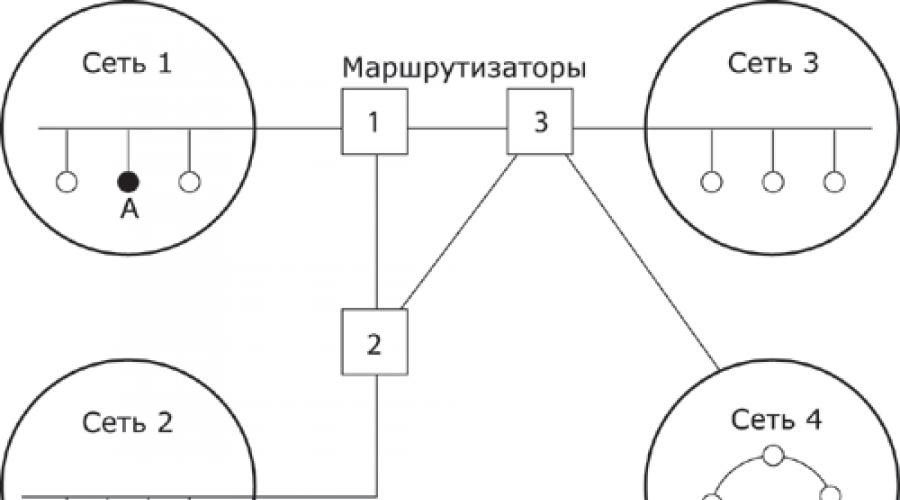
On rice. 11.8 shows four networks connected by three routers. Between nodes A and B of this network there are two route: first - through routers 1 and 3, and the second - through routers 1, 2 and 3.
 Rice. 11.8. An example of a composite network.
The problem of choosing the best path is called routing, and its solution is one of the main tasks network layer. This problem is compounded by the fact that the shortest path is not always the best. Often the selection criterion route is the data transfer time; it depends on the bandwidth of communication channels and traffic intensity, which can change over time. Some routing algorithms try to adapt to load changes, while others make decisions based on long-term averages. Choice route may be subject to other criteria such as reliability transmission.
In general, the functions network layer wider than the messaging functions for links with a non-standard structure, which we considered using the example of combining several local networks. network layer also solves the problems of harmonizing different technologies, simplifying addressing in large networks and create reliable and flexible barriers to unwanted traffic between networks.
Messages network layer called packages (packet ). When arranging delivery packages on network layer the concept of "network number" is used. In this case address The recipient consists of the high part - the network number and the low part - the node number in this network. All nodes on the same network must have the same upper part addresses, so the term "network" on network layer Another, more formal, definition can be given: net is a collection of nodes network address which contains the same network number.
On network layer two types of protocols are defined. The first kind - network protocols- implement promotion packages through the network. It is these protocols that are usually meant when talking about protocols. network layer. However, often to network layer include another kind of protocols called routing information exchange protocols or simply routing protocols. With these protocols routers collect information about the topology of interconnections. Protocols network layer implemented by software modules of the operating system, as well as software and hardware routers.
On network layer there are another type of protocols that are responsible for displaying addresses node used on network layer, to a local network address. Such protocols are often called Address Resolution Protocol , ARP . Sometimes they are not considered network layer, and to channel, although the subtleties of classification do not change the essence.
Protocol examples network layer are the IP internetworking protocol stack TCP/IP and Internet Protocol packages IPX stack Novell.
Network OSI model is the reference model of interaction open systems, in English sounds like Open Systems Interconnection Basic Reference Model. Its purpose in a generalized representation of the means of network interaction.
That is, the OSI model is the generalized standards for software developers, thanks to which any computer can equally decrypt data transmitted from another computer. To make it clear, I will give a real-life example. It is known that bees see everything around them in ultraviolet light. That is, our eye and the bee perceive the same picture in completely different ways, and what insects see may be imperceptible to human vision.
It's the same with computers - if one developer writes an application on any programming language, which understands its own computer, but is not available to any other, then on any other device you will not be able to read the document created by this application. Therefore, we came up with the idea that when writing applications, follow a single set of rules that is understandable to everyone.
OSI levels
For clarity, the process of network operation is usually divided into 7 levels, each of which has its own group of protocols.
network protocol- these are the rules and technical procedures that allow computers connected in a network to connect and exchange data.
A group of protocols united by a single end goal is called a protocol stack.
To perform different tasks, there are several protocols that deal with system maintenance, such as the TCP/IP stack. Let's take a closer look here at how information from one computer is sent over a local network to another computer.
SENDER computer tasks:
- Get data from app
- Break them into small packages if the volume is large
- Prepare for transmission, that is, specify the route, encrypt and re-encode to a network format.
Tasks of the RECIPIENT's computer:
- Receive data packets
- Remove service information from it
- Copy data to clipboard
- After complete reception of all packets, form the initial data block from them
- Give it to the application
In order to correctly perform all these operations, a single set of rules is needed, that is, the OSI reference model.
Let's get back to the OSI layers. It is customary to count them in the reverse order and in the upper part of the table are network applications, and in the lower part - the physical medium of information transfer. As the data from the computer descends directly to network cable, protocols operating at different levels gradually transform them, preparing them for physical transmission.
Let's analyze them in more detail.
7. Application layer (Application Layer)
His task is to take network application data and send to level 6.
6. Presentation Layer
Translates this data into a single universal language. The fact is that each computer processor has its own data processing format, but they must get into the network in 1 universal format This is exactly what the presentation layer does.
5. Session Layer
He has many tasks.
- Establish a session with the recipient. The software warns the receiving computer that data is about to be sent to it.
- This is where name recognition and protection comes in:
- identification - name recognition
- authentication - password verification
- registration - assignment of authority
- Implementation of which party is transferring information and how long it will take.
- Arrangement of checkpoints in the general data stream so that in case of loss of some part it is easy to establish which part is lost and should be resent.
- Segmentation is the division of a large block into small packages.

4. Transport Layer
Provides applications with the necessary degree of protection when delivering messages. There are two groups of protocols:
- Protocols that are connection oriented - they monitor the delivery of data and optionally request retransmission on failure. This is TCP, the Transfer Control Protocol.
- Connectionless (UDP) - they just send blocks and do not track their delivery further.
3. Network layer (Network Layer)
Provides end-to-end transmission of a packet by calculating its route. At this level, in packets, to all previous information generated by other levels, IP addresses of the sender and recipient are added. From that moment on, the data packet is called the PACKAGE itself, which has (IP protocol is an internetworking protocol).
2. Data Link Layer
Here the packet is transmitted within the same cable, that is, one local network. It only works up to the edge router of one LAN. The link layer adds its own header to the received packet - the MAC addresses of the sender and recipient, and in this form the data block is already called a FRAME.

When transmitted outside one local network, the packet is assigned the MAC not of the host (computer), but of the router of another network. From here, the question of gray and white IPs appears, which were discussed in the article to which the link was given above. Gray is an address within one local network that is not used outside of it. White - a unique address in everything global internet.
When a packet arrives at the border router, the IP of the packet is replaced with the IP of this router and the entire local network goes to the global, that is, the Internet, under one single IP address. If the address is white, then the part of the data with the IP address is not changed.

1. Physical layer (Transport layer)
Responsible for transformation binary information V physical signal, which is sent on the physical data link. If it is a cable, then the signal is electrical; if it is a fiber optic network, then it is an optical signal. This transformation is carried out using network adapter.

Protocol stacks
TCP/IP is a protocol stack that manages the transmission of data both on a local network and global network Internet. This stack contains 4 levels, that is, according to the OSI reference model, each of them combines several levels.
- Applied (according to OSI - applied, presentation and session)
The following protocols are responsible for this layer:- TELNET - remote communication session in the form command line
- FTP - File Transfer Protocol
- SMTP - Mail Transfer Protocol
- POP3 and IMAP - receiving postal items
- HTTP - work with hypertext documents
- Transport (the same for OSI) - these are the TCP and UDP already described above.
- Internetwork (over OSI - network) is an IP protocol
- The level of network interfaces (according to OSI - channel and physical) Network adapter drivers are responsible for the operation of this level.
Terminology when designating a data block
- A stream is the data that is operated on at the application level.
- A datagram is a block of output data with UPD, i.e., which has no guaranteed delivery.
- Segment - a block guaranteed for delivery at the output with TCP protocol
- A packet is a block of data output from the IP protocol. since it is not yet guaranteed to be delivered at this level, it can also be called a datagram.
- A frame is a block with assigned MAC addresses.
RS-232 protocol.
There are several physical layer protocols that are focused on working with UART type ports. One such protocol is RS-232.
The abbreviation RS stands for Recommended standard (that is, de jure it is not a standard). The RS-232 protocol defines a physical layer protocol that is often used in conjunction with a UART (that is, it uses asynchronous start-stop mode, the NRZ physical encoding method, for transmission). Main characteristics of RS-232:
· Communication medium – copper wire. The signal is unbalanced (potential). In this case, the signal is transmitted over one individual wire of the cable, the transmitter and receiver each have one output, unlike a differential signal (each signal is transmitted over an individual pair). The second wire is common (ground), used by all signals at once and connected to the common power outputs of the receiver and transmitter. This method reduces the cost of the connecting cable, but also worsens the noise immunity of the system.
· The number of nodes is always 2. The transmitter of the first node is connected to the receiver of the second and vice versa. Accordingly, full-duplex operation is always used - data is transmitted in both directions simultaneously and independently.
· The maximum wire length is 15.25 m for a transmission rate of 19.2 Kbps.
· Signal voltage levels at the transmitter output: bipolar signal, logical “1” corresponds to voltage -5 ¸ -15 V., logical “0” - +5 ¸ +15 V.
· The minimum voltage levels at the input of the receiver ± 3 V.
· Current in the line - 500 mA (actually produced RS-232 drivers allow current within 10 mA).
There is currently a large number of drivers that convert signals from digital levels (unipolar signal limited by the level digital power) to the RS-232 level.
RS-485 protocol.
Provides a simplified equal (at the physical level) connection of an arbitrary number of devices to the data line.
Main characteristics:
· the data transmission medium is always twisted pair. Usually 1 pair is used (half duplex mode), 2 pairs can be used (full duplex mode, which is not standard). Pair lines are also labeled A and B. Shielded twisted pair is recommended;
· transmission method - half duplex (when using one pair) or full duplex (when using two pairs). In the latter case, the communication mode is similar to the RS-422 mode.
maximum transmission range - 1220 m at a speed of 100 kbps;
· maximum speed transmissions - 10 Mbit / s at a distance of up to 15 m;
The transmitter signal is bipolar. Potential ratios of lines A and B: state 0 - A>B, state 1 - B>A. The potential difference between A and B should be 1.5 - 5 V, the current level in the line should be up to 250 mA.
Initially, the protocol provided for connecting up to 32 devices to one line, but line driver manufacturers increased this number to 128-256.
Local area networks were built using several types of physical layer protocols that differ in the type of transmission medium, frequency range of signals, signal levels, and encoding methods.
The first technologies building a LAN that received commercial recognition were proprietary solutions ARCNET (Attached resource computer NETwork) And token ring(marker ring), however, in the early 90s of the last century, they were gradually replaced almost everywhere by networks based on the family of protocols ethernet.
This protocol was developed by Xerox's Palo Alto Research Center (PARC) in 1973. In 1980, Digital Equipment Corporation, Intel Corporation, and Xerox Corporation jointly developed and adopted the Ethernet specification (Version 2.0). At the same time, the IEEE (Institute of Electrical and Electronics Engineers) organized the 802 committee for the standardization of local networks, as a result of which the IEEE 802.x family of standards was adopted, which contain recommendations for designing the lower levels of local networks. This family includes several groups of standards:
802.1 - network aggregation.
802.2 - Logical link management.
802.3 - LAN with multiple access, carrier sense and collision detection (Ethernet).
802.4 - LAN topology "bus" with the transfer of the token.
802.5 - LAN topology "ring" with the transfer of the token.
802.6 - city-wide network (Metropolitan Area Network, MAN).
802.7 - Broadcast Technical Advisory Group.
802.8 -- Fiber-Optic Technical Advisory Group.
802.9 - Integrated Voice/Data Networks.
802.10 - Network security.
802.11 - Wireless network.
802.12 - LAN with access by request priority (Demand Priority Access LAN,
lOObaseVG-AnyLan).
802.13 - the number was not used!!!
802.14 - Data transmission over cable TV networks (not active since 2000)
802.15 - Wireless Personal Area Networks (WPAN) e.g. Bluetooth, ZigBee, 6loWPAN
802.16 - WiMAX wireless networks ( World-wide Iinteroperability for Mmicrowave Access, read in Russian wymax)
802.17 is called RPR (Resilient Packet Ring). It has been developed since 2000 as a modern urban backbone network.
Each group has its own subcommittee that develops and adopts updates. The IEEE 802 series standards cover two layers of the OSI model, so far we are only interested in those of them and in the part that describe the physical layer.
ethernet (802 .3) - LAN with multiple access, carrier sense and collision detection.
Ethernet is the most widely used local area network protocol today. Moreover, the IEEE 802.3 specification today describes several options for the physical implementation of a LAN with different transmission media and data transfer rates.
The basic property that unites all these specifications is access control method to the communication medium. For Ethernet it is carrier sense multiple access with collision detection(CSMA/CD, Carrier Sense Multiple Access with Collision Detection). In an Ethernet network, all nodes are equal, there is no centralized control of their activity or differentiation of powers (as, for example, in Token ring). Each node continuously listens to the transmission medium and analyzes the contents of all data packets, if the packet is not intended for this node, it is not of interest to him and upper levels not getting through. Problems usually arise during transmission, since no one guarantees that two nodes will not try to transmit at the same time (resulting in an imperceptible superposition of two signals in the cable). To prevent such situations collisions) each node, before starting the transmission, makes sure that there are no signals from others in the cable network devices (carrier sensing). But this is not enough to prevent collisions due to the limited speed of signal propagation in the transmission medium. It is possible that some other node has already started the transmission, it's just that the signal from it has not yet reached the device we are considering. That is, in an Ethernet network, situations are possible and regular when two or more nodes simultaneously try to transmit data interfering with each other. The procedure for resolving such a collision is that, having detected the presence of an alien signal in the cable during transmission, all nodes that have fallen into such a situation stop transmission and attempt to resume it through various time intervals.
The disadvantage of the probabilistic access method is the indefinite frame transit time, which increases sharply with increasing network load, which limits its use in real-time systems.
Let us consider in more detail the collision detection procedure and the interdependence of the permissible network sizes on the data transfer rate and the length of information packets transmitted over the network. We will analyze the content and internal structure of Ethernet frames at the link level. For now, we will simply take into account that with a signal propagation speed in the conductor of about 200,000,000 m/s during network operation Ethernet adapter IEEE 802.3 with a data rate of 10 Mbps, it takes 0.8 µs to send one byte and it is a wave packet with a length of about 150 m.
Now let's go back to the drawing. In order for workstation A to know that a collision occurred during transmission, the superposition of the "colliding" signals must reach it before the transmission is completed. This imposes restrictions on the possible minimum length of sent packets. Indeed, if you use packets shorter than the length of the cable between workstations "A" and "B", it is possible that the packet was completely sent by the first station (and it already decided that the transfer was successful), and it has not even reached the second, and she has every right to start transferring her data at any time. It is easy to see that such misunderstandings can be avoided only by using packets of such length that during their transmission the signal has time to reach the most remote station and return back.
At a data rate of 10 Mbps, this problem did not play a significant role and the minimum frame length was limited to 64 bytes. During their transmission, the first bits have time to run about 10 km, and for networks with a maximum segment length of 500 m, all the necessary conditions are met.
When moving to 100 Mbps, the length of the minimum frame will be reduced by a factor of 10. This significantly tightens the parameters of the network and the maximum distance between stations has been reduced to 100 m.
At a speed of 1000 Mbps, 64 bytes are transferred in just 0.512 µs, and therefore, in gigabit networks, the minimum frame length had to be increased by 8 times to 512 bytes. If there is not enough data to fill the frame, the network adapter simply pads it with a special sequence of characters up to this length. This technique is called "carrier expansion".
To solve the problem of collision detection, media extension wastes the bandwidth of the data link when transmitting small packets. To reduce the influence of this factor in a gigabit Ethernet adapter, if there are several short frames ready for transmission, it is allowed to form one common frame of “normal” length up to 1518 bytes from them in a certain way.
Furthermore, it has been proposed to allow longer frame lengths than previous Ethernet standards. This proposal was implemented in the form of so-called "jumbo" - frames up to 9018 or even more bytes long.
IEEE 802.3 defines several different physical layer standards. Each of the IEEE 802.3 physical layer protocol standards has a name.
|
Characteristics | |||||||
|
Speed, Mbps | |||||||
|
Max. segment length, m | |||||||
|
Transmission medium |
50 ohm coax (thick) |
FOC 1270 nm |
FOC, 830, 1270 nm | ||||
|
Topology | |||||||
|
Transmission type |
half duplex |
The table shows that the original common bus topology (thick Ethernet, thin Ethernet) was quickly replaced by a star.
Token Ring (IEEE 802.5)
The Token Ring network was introduced by IBM in 1984 as part of its proposed method of networking the entire range of IBM computers and computer systems. In 1985, the IEEE 802 committee adopted the IEEE 802.5 standard based on this technology. Fundamental difference from Ethernet - deterministic meth Environment access code in a predefined order. Implemented token passing access (also used in ARCnet and FDDI networks).
Ring topology means the ordered transmission of information from one station to another in one direction, strictly in the order of inclusion. The ring logical topology is implemented on the basis of a physical star, in the center of which there is a multi-station access unit (MSAU - Multi-Station Access Unit).
At any time, only one station can transmit data, capturing marker beforemortar(token). When data is transmitted, a busy mark is made in the marker header, and the marker turns into a frame start frame. The rest of the stations transmit bit by bit the frame from the previous (upstream) station to the next (downstream). The station to which the current frame is addressed stores a copy of it in its buffer for further processing and broadcasts it further along the ring, marking it as received. Thus, the frame through the ring reaches the transmitting station, which removes it from the ring (does not broadcast further). When the station completes the transmission, it marks the token as free and passes it further along the ring. The time during which the station has the right to use the marker is regulated. The token acquisition is based on the priorities assigned to the stations.
With the growth of node activity, the bandwidth available to each of the nodes narrows, but there is no landslide degradation of performance (as in Ethernet). In addition, the prioritization mechanism and token tenure limits allow privileged hosts to allocate guaranteed bandwidth regardless of overall network load. The number of nodes in one ring must not exceed 260 (an Ethernet segment theoretically allows 1024 nodes). The transmission rate is 16 Mbps, the frame size can be up to 18.2 KB.
Packet transmission time limit token ring 10 ms. With a maximum number of subscribers of 260, the full cycle of the ring will be 260 x 10 ms = 2.6 s. During this time, all 260 subscribers will be able to transfer their packages (if, of course, they have something to transfer). During the same time, a free token will definitely reach each subscriber. The same interval is the upper limit of the access time token ring