Connecting multiple switches. Pass-through switch: device connection diagram from different places
Read also
Pass-through switches are designed to turn lights on and off from various points. They can be installed in and more, depending on the need to create the convenience of switching on and off. First of all, such switches are installed in inconvenient places, such as long corridors, flights of stairs, and so on. For example, in a long corridor, when you turn on the light with a conventional switch located at the beginning of the corridor, you need to return from the other end to turn off the light.
The pass switch scheme allows you to turn on the light at the beginning of the corridor, and turn it off at the end of the corridor. For this, two pass-through switches are installed.
2 position switch
The easiest way to connect at two points. The basis of the circuit are pass-through switches in the amount of two pieces. Each of them has three contacts and a two-position switch. The switching itself must be carried out in a changeover mode. In this case, one contact will be common to the other two. In each switching option, it alternately closes with one of the two remaining contacts. That is, all three contacts cannot be closed at the same time.
The principle of connection in both schemes is common. Each circuit includes pass-through switches, a junction box, a lighting device and connecting wires. Moreover, in different options connections, it can be cables with two, three or four cores. In a two-switch circuit, the neutral wire runs to the junction box from the power source, and then to the lighting fixture.
The phase wire, through the junction box, is connected to the common contact of a switch. The two switching contacts in both switches are also interconnected through the box. From the common contact of another switch, the wire is led through the box to the second contact of the lighting device.
Three point connection
The thru-switch circuit for three places has very few differences from the two-place circuit. It's just that a third switch of a different design is added to the circuit. If you press one key, then two contacts, independent of each other, will be simultaneously transferred. This switch requires a cable with four cores.

The design of such schemes is quite simple and does not require any additional elements. There are certain restrictions on the number of control places. Practical installation is not particularly difficult. All elements are installed in their places at pre-marked points and, then, connected according to the scheme.
First of all, before choosing and buying, you need to decide what it is - a pass-through switch, what it is for, and how it differs from the usual one, two and three-gang ones.
A single-button walk-through switch is required to control one circuit or lighting line from several points located in different parts room or the whole house. That is, with one switch you turn on the lighting when you enter a room or corridor, and with another, but at a different point, you turn off the same lighting.
This is often used in bedrooms. I went into the bedroom, turned on the light near the door. He lay down on the bed and turned off the light at the head or near the bedside table.
In two-story mansions - he turned on the light bulb on the first floor, climbed the stairs to the second and turned it off there. 
Selection, design and differences of walk-through switches
Before assembling such a control scheme, here are some things to pay special attention to:
1 To connect pass-through switch light needed three-core cable - VVGng-Ls 3 * 1.5 or NYM 3 * 1.5mm2 2 Do not try to assemble a similar circuit on ordinary switches.
 The main difference between conventional and pass-through is the number of contacts. Simple single-key have two terminals for connecting wires (input and output), and pass-through - three! 
On simple, the lighting circuit can be either closed or open, there is no third.
The checkpoint is more correctly called not a switch, but a switch.
Since he, it switches the circuit from one working contact to another.

By appearance, in front they can be exactly the same. Only on the pass-through key can there be an icon of vertical triangles. However, do not confuse them with flip or cross (more on them below). These triangles look in the horizontal direction. 
But on the reverse side, you can immediately see the whole difference:
- the feedthrough has 1 terminal at the top and 2 at the bottom
- normal 1 top and 1 bottom
Many in this parameter confuse them with two-key ones. However, two-key ones will also not work here, although they also have three terminals. 
There is a significant difference in the work of contacts. When one contact is closed, the pass-through switches automatically close the other, but there is no such function in two-button switches. 
Moreover, the intermediate position, when both circuits are open, does not exist at the checkpoint at all.
Connecting a pass switch
First of all, it is necessary to correctly connect the switch itself in the socket. Remove the key and overlay frames. 
When disassembled, you can easily see the three contact terminals. 
The most important thing is to find common ones. On quality products, a diagram should be drawn on the reverse side. If you understand them, then you can easily navigate through it. 
If you have a budget model, or for you any electrical circuits are a dark forest, then on help will come an ordinary Chinese tester in continuity mode, or an indicator screwdriver with a battery.
Using the probes of the tester, alternately touch all the contacts and look for the one on which the tester will "beep" or show "0" at any position of the ON or OFF key. It is even easier to do this with an indicator screwdriver. 
After you have found a common terminal, you need to connect the phase from the power cable to it. Attach the remaining two wires to the remaining terminals.
And which one goes where, does not make a significant difference. The switch is assembled and fixed in the socket. 
With the second switch, do the same operation:
- looking for a common thread
- connect a phase conductor to it, which will go to the light bulb
- connect two other wires to the remaining ones

Scheme of connecting the wires of the pass-through switch in the junction box

Circuit without ground conductor
Now the most important thing is to correctly assemble the circuit in the junction box. Four 3-core cables should go into it:
- power cable from the switchboard lighting machine
- cable to switch #1
- cable to switch #2
- cable for lamp or chandelier

When connecting wires, it is most convenient to orient by color. If you use a three-core VVG cable, then it has two most common color markings:
- white (gray) - phase
- blue - zero
- yellow green - earth
or the second option:
- White gray)
- brown
- black
To choose a more correct phasing in the second case, refer to the tips from the article "" 
Connect the zero core from the cable of the introductory machine and the zero that goes to the lamp at one point through the car terminals. 
Similarly to the neutral wires, you combine the "ground" from the input cable with the "ground" of the outgoing cable for lighting. 
This wire is connected to the body of the lamp. 
The phase from the input cable must be connected to the phase of the outgoing wire to the common terminal of the feed-through switch No. 1. 
And connect the common wire from the feed-through switch No. 2 with a separate wago clamp to the phase conductor of the cable for lighting. 
Having completed all these connections, it remains only to connect the secondary (outgoing) cores from the switch No. 1 and No. 2 to each other. It doesn't really matter how you connect them. 
You can even mix up the colors. But it is better to stick to the colors, so as not to get confused in the future.
The basic connection rules in this scheme that you need to remember:
- the phase from the machine must come to the common conductor of the first switch
- and the same phase should go from the common conductor of the second switch to the light bulb

- the other two auxiliary conductors are interconnected in the junction box
- zero and earth are fed directly without switches directly to the light bulbs
Toggle switches - lighting control scheme from 3 places
 But what if you want to control one lighting from three or more points. That is, there will be 3, 4 switches in the circuit, etc. It would seem that you need to take another pass-through switch and that's it.
However, a switch with three terminals is no longer suitable here. Since there will be four connected wires in the junction box.
Here, a toggle switch, or as it is also called a cross, cross, intermediate switch, will come to your aid. Its key difference is that it has four exits - two from below and two from above. 
And it is installed just the same in the interval between the two checkpoints. Find two secondary (not main) wires from the first and second pass-through switch in the junction box.
Disconnect them, and connect a crossover between them. Connect those wires that come from the first one - to the input (follow the arrows), and those that go to the second one - to the output terminals. 
Always check the circuit on the switches! It often happens that their entrance and exit is on the same side (top and bottom). For example, the wiring diagram for the changeover Legrand Valena: 
Naturally, you don’t need to stuff the flip-over into the junction box. It is enough to bring the ends of a 4-core cable from it there. And in the meantime, place the switch in any convenient place - near the bed, in the middle of a long corridor, etc. You can turn the light on and off from anywhere. 
The most important advantage of this scheme is that it can be changed indefinitely and add as many toggle switches as you like. That is, there will always be two walk-throughs (at the beginning and at the end), and in the interval between them there will be 4, 5 or at least 10 changeovers. 
Connection errors
Many at the stage of searching and connecting a common terminal in a pass-through switch make a mistake. Without checking the circuit, they naively believe that the common terminal is the one with only one contact.
They assemble the circuit in this way, and then the switches for some reason do not work correctly (they depend on each other).
Remember that on different switches, the common contact can be anywhere!
And it is best to call it, what is called "live", with a tester or an indicator screwdriver. 
Most often, such a problem is encountered when installing or replacing pass-through switches from different companies. If everything worked before, and after replacing one, the circuit stopped working, then the wires were mixed up.
But it may also be an option that the new switch is not a pass-through at all. Also remember that the backlight inside the product can in no way affect the switching principle itself.
Another common mistake is incorrect connection of crossovers. When both wires, from the passage No. 1, are put on top contacts, and from No. 2 to the lower ones. Meanwhile, the circuit and switching mechanism of the cross switch is completely different. And you need to connect the wires crosswise. 
Flaws
1 The first of the shortcomings of walk-through switches is the lack of a specific position of the ON / OFF key, which is in the usual ones.
If your light bulb has burned out and needs to be replaced, with this scheme it is not immediately possible to understand whether the light is on or off.
It will be unpleasant when, when replacing, the lamp can simply explode before your eyes. In this case, the simplest reliable way turn off the lighting in the dashboard.
2 The second disadvantage is a large number of connections in junction boxes. And the more light points you have, the more of them will be in the junction boxes. Connecting the cable directly according to diagrams without junction boxes reduces the number of connections, but at times can increase either the cable consumption or the number of its cores.
If your wiring goes under the ceiling, then you will have to lower the wire from there to each switch, and then lift it back up. The best option here, the application of impulse relays.
There can be many situations when you need to connect two lamps to the same power supply using just one switch. Most often, single-key and two-key switches are used, less often - cross switches. If, as a rule, there are no difficulties with connecting one light bulb, then the presence of 2 light sources makes home craftsmen think about their correct connection to the network. However, I would like to list all possible ways, based not only on the type of switch, but also on the types of light bulbs and how they are connected. Next, we will describe in detail how to connect two light bulbs to one switch, providing all the necessary wiring diagrams.
Types of lamps and switches
Before proceeding directly to the installation, you need to clearly understand that there are several types of light bulbs that are connected to the network both directly and through ballast or rectifier-step-down equipment. In any case, each of them has its own operating voltage and power, on which the current also depends, respectively.
Types of artificial light sources often used in everyday life:
- Incandescent and halogen, the principle of operation is the same, only in some there is a vacuum, and in others there are special halogen vapors that increase the service life.
- Luminescent, as well as their variety, the so-called housekeeper and sodium.
- LED, working on LED systems and features semiconductor diode emit luminous flux.
Lighting control from two places is not a new idea, but it is actively used today. For its implementation, pass-through switches are used.
What is the difference between a switch and a normal switch?
If you look at the passage switch from the side, then no external differences you won't find. The essential and only difference between such switches and simple ones lies inside their design.
A conventional single-pole single-gang switch has two contacts in its design, fixed and movable. The moving contact is driven by a key that we press by hand and closes with the fixed contact. This closes the electrical circuit and supplies power to the lamp. There are also designs of bipolar single-gang switches that essentially perform the same function as the previous one. Its difference lies in the fact that the zero core going to the lamp breaks similarly to the phase one. This was done to improve security.
Picture 1. circuit diagram connection of single-pole and double-pole single-gang switches
The feed-through switch has two fixed and one moving contacts. The movable contact is always closed with one of the fixed ones. When a key is pressed and moved from one position, for example, "off" to another position - "on", the movable contact also changes its position, opening with a closed contact and closing with an open one. That is, the pass-through switch does not have an “off” position and it does not work as a switch, but as a switch. Therefore, in the technical literature and in the catalogs of manufacturers, it is correctly called a switch. For example: "single-pole, single-gang, two-way switch." Keep this in mind when you buy switches for assembling a control circuit from two places.
In addition to single-pole switches, there are two-pole and even three-pole switches.
For ease of understanding, in this article we will use the expression not a switch, but a pass-through switch, since it is more often used among people.
Where is this lighting control system used?
The most commonly considered lighting control system is used in public and industrial premises, namely: in long corridors, tunnels, walk-through rooms, that is, in rooms where there are two doors equally serving as an entrance and exit, in flights of stairs and other places. In all of these cases, walk-through switches are installed next to the doors.
If we talk about residential premises, then the installation location of the walk-through switches can be, for example, Entrance door into the room and place on the wall next to the bedside table. In this case, the person entering the room will turn on the light by pressing the pass switch located next to the door, and sitting on the bed, without getting up, will be able to turn it off with the second pass switch located next to the bed.
With the help of pass-through switches, you can control both one lamp or lamp, and their group. For each case apply different types pass-through switches (single-key, two-key, three-key). The main goal pursued by a person by installing such switches is the convenience of controlling the light and reducing energy costs.
Connecting a single-gang switch
Figure 2 shows a schematic diagram of the connection of feed-through switches designed to control one lamp or one group of lamps from two, remote friend from a friend, places. As you probably already understood, a single-pole feed-through switch has two fixed and one changeover contact. Supply voltage is applied to the changeover contact of one of the switches. The changeover contact of the second switch is connected to the lamp, and the lamps, in turn, to the neutral wire of the mains. The fixed contacts of the first switch will be connected by two separate conductors to the two fixed contacts of the second switch.

Figure 2. Schematic diagram of connecting a through switch with one pole and one key
In the diagram, the position of the changeover contacts of both switches is the same, which corresponds, for example, to the lowered position of their keys. The electrical circuit is then open. If we press the key of the first switch and move it to the raised position, then the changeover contact of this switch, respectively, will also change its position and close electrical circuit. The chain will flow electricity(the direction of current is shown by arrows), and the lamp will start to glow. If you now press the key of the second switch and also change its position, the circuit will again be open and the lamp will go out.
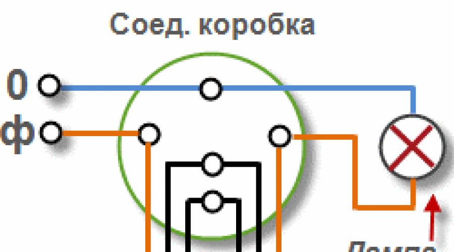
For a more visual representation of how the conductors are connected, Figure 3 shows the wiring diagram for connecting the feed-through switches. The green circle is nothing more than a junction box, inside which the wires are connected. The round pieces inside the box are soldered wires, made in the form of twists with welding, crimped with self-clamping insulating caps, connected by terminals or a screw connection. Everything else I think is clear.

Figure 3. Wiring diagram for connecting single-pole single-gang switches
Figure 4 below shows the layout of the equipment and wiring. The connection of wires in this case is carried out in two junction boxes. 1 installed above the walk-through switches 3 . This was done to save wires. In the case of installing one junction box and assembling the circuit in it, in addition, two more wires would have to be laid from the box to the switch closest to us. If the supply wires were supplied from the side of the lamp 2 , then all connections could be made in one box without unnecessary wires.
Here: L- linear (phase) wire; N- neutral wire; PE- ground wire.

Figure 4. An example of a lighting control scheme from two places using single-pole single-gang switches
Connecting a double-gang switch
The electrical circuit of the two-pole double-gang switch is similar wiring diagram single-pole single-gang switch. The difference is that one more set of contacts is built into one housing (one more movable and two fixed contacts). Externally, the double-gang switch is similar to a regular double switch.
The purpose of two-button walk-through switches is to divide one large group of lamps or fixtures into two groups. That is, their work is similar to that of a conventional double switch installed in the living room and designed to turn on the lamps of a large beautiful chandelier.
The two-gang switch is connected in accordance with the circuit diagram shown in Figure 5. The directions of the currents are indicated by arrows.
Figure 5. Schematic diagram of connecting a double-gang switch

Figure 6. Wiring diagram for connecting two-pole two-button switches
Lighting control from three or more places
There are times when it becomes necessary to turn on the light in the room not from one or two places, but from three, four or more. To implement such a scheme, manufacturers produce intermediate switches (switches). An example of a control scheme from three places is shown in Figure 7.
Figure 7. Schematic diagram of the connection of two-pole two-button feed-through and intermediate switches
As can be seen from the diagram, the intermediate switch has four fixed and two moving contacts. When a key is pressed, the moving contacts simultaneously switch from one pair of fixed contacts to another pair.

Figure 8. Wiring diagram for connecting single-pole single-gang switches and an intermediate switch
In order to be able to turn the light on and off, for example, from four places, another intermediate switch is installed. It is placed between one of the pass-through switches and the existing intermediate switch. By analogy, you can increase the number of control places to any value.

Figure 9. Schematic diagram of lighting control from five places
Right assembled circuit connecting a double switch allows you to control two different groups illumination from two places independently of each other. Two two-key walk-through switches will work in two directions.
Installation instructions:
- Two two-gang switches are mounted at selected locations in installation boxes (sockets).
- All groups of connected lighting are placed: lamps, sconces or a chandelier with several points of light. One three-core cable should be suitable for each light source: phase (L), protective (ground), working zero (N).
- A cable of the required length (3x1.5 mm2) is selected, taking into account the fact that 6 contacts are suitable for the switches - two three-core cables.
- In the junction box (RK), wires are connected according to the diagram.
- It is possible to install such a circuit using four single pass-through switches, but the replacement will not be rational. Installation of double switches is more profitable, as there is a saving of cable and junction boxes.
A double pass switch can be converted into a single cross switch. To do this, the contacts are interconnected, and the keys are fixed together for joint simultaneous operation.
much simpler and can help to organize the control of electric lighting from two points.
You can find out how to choose and install a ventilation system for a country house by clicking on this.
Also, any pass-through switch can be used as a normal one. In this case, one of the contacts is either not connected at all, or is also connected for another independent adjustment of the existing lighting line. Now you know how to properly connect, or, as the electricians say, turn off, a two-gang pass-through switch.