ME connection diagrams with several network interfaces. Firewalls
Read also
1.2 Basic ME connection diagrams
When connecting corporate network access to global networks, it is necessary to restrict access to the protected network from global network and from the protected network to the global network, as well as to ensure the protection of the connected network from remote UA from the global network. At the same time, the organization is interested in hiding information about the structure of its network and its components from users of the global network. Working with remote users requires the establishment of strict access restrictions to information resources protected network.
Often there is a need to have several segments with different levels of security in the corporate network:
freely accessible segments (for example, an advertising WWW server);
Segment with limited access (for example, for access to employees of the organization from remote sites);
closed segments (for example, the financial local subnet of the organization).
To connect the ME, various schemes can be used, which depend on the operating conditions of the protected network, as well as on the number of network interfaces and other characteristics used by the ME. Schemes are widely used:
Network protection using a shielding router;
unified protection local network;
unified protection of the local network;
· with protected closed and not protected open subnets;
· with separate protection of closed and open subnets.
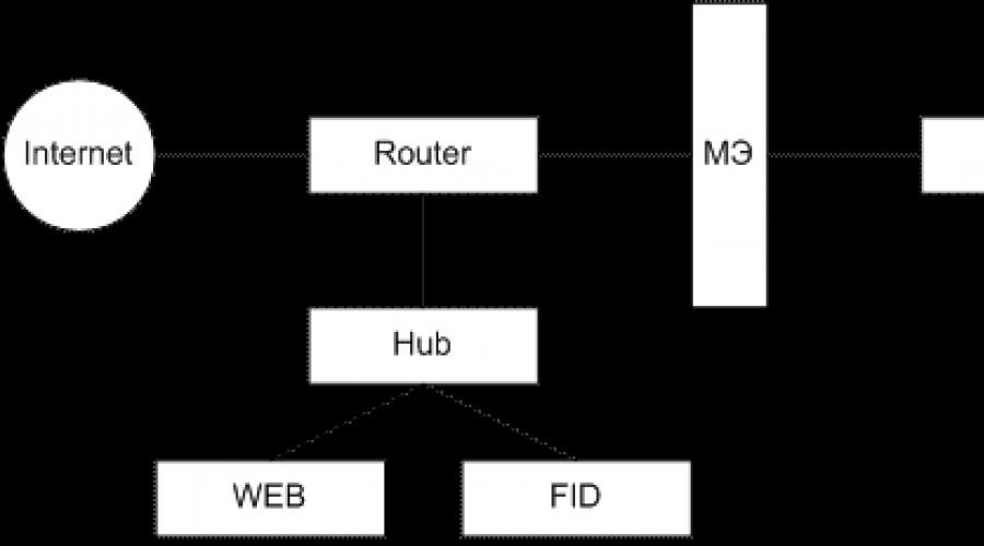
Let's take a closer look at the scheme with a protected closed and unprotected open subnet. If there are public open servers in the local network, then it is advisable to take them out as an open subnet to the ME (Figure 1).
This method has a high security of the closed part of the local network, but provides a reduced security of open servers located up to the ME.
Some MEs allow you to host these servers on your own. However, this solution is not the best from the point of view of the security of the DOE itself and the loading of the computer. It is advisable to use the ME connection scheme with a protected closed subnet and an unprotected open subnet only if there are low security requirements for an open subnet.
If there are increased requirements for the security of open servers, then it is necessary to use a scheme with separate protection of closed and open subnets.
Global international computer network Internet
The Internet is based on large channels bandwidth- backbones connecting large network nodes. There are two main ways to connect a user to the Internet: ? permanent connection via dedicated line...
Using SQL in Application Programming
Once on the site, the user can register or log in. If the user tries to subscribe to the mailing list without authorization, the following message will pop up: modal window with an invitation to enter the site...
Study of the organization of a small business access network to the Internet
automated workplace(AWP) can be connected to the global network in various ways: Connecting a second computer to the Internet via a router If the office has a stationary computer and a second stationary computer has been purchased ...
Typical circuit connection of a quartz resonator from 3 to 20 MHz to the AT91SAM7SE microcontroller is shown in fig. 4. Fig. 4...
Combo USB audio device with stand-alone MP3 player and Bluetooth enabled
USB combo audio device with standalone MP3 player functionality and Bluetooth support
The power supply for the F2M03MLA must be chosen carefully and may affect the performance of the module or even damage it. The manufacturer recommends using the XC6209B332MR voltage regulator from Torex...
Basic network protection schemes based on firewalls
When connecting a corporate or local network to global networks, it is necessary to: · protect the corporate or local network from a remote NSD from the side of the global network; hiding information about the structure of the network and its components from users ...
Combination Circuit Design
A combinational circuit (CS) is a circuit of logical (switching) elements that implements a Boolean function or a set of Boolean functions. In the general case, the CS can be represented by the diagram shown in Fig. 1, where x1, x2,....xn are the inputs of the COP, f1, f2,....
Design microprocessor system management
Figure 2.10 shows the connection diagram of the speaker BA1 for sound signaling. Transistor VT1 current amplifies the output signal from the RC0 line of the port. Figure 2.10 - Emergency sensor connection diagram In Figure 2...
Development and implementation of a computing device in the program "Minecraft"
Logical elements (for some reason they are called gates or gates in minecraft) are the basis of all mechanisms. The NOT (inverter) element returns the opposite signal to the one received. This is an implementation of the logical NOT. Rice. 4. Inverter...
Development of a controller for a trackball pointer
The complexity of powering an optocoupler lies in the fact that + 5V needs to be powered by a photodiode, which is supplied with + 2.5V. Therefore, we need to add two resistors (R4 and R5) to get a voltage divider, they had the voltage drop we needed. Rice...
Communication via telecommunication networks
satellite channel. Enough high speed work, mobility. Such a connection requires expensive equipment and complex settings, high channel rental costs, dependence on weather conditions...
Database management systems in the enterprise
The software department has Pentium IV class machines with Intel processors Pentium 2.6 and Intel Celeron 1.7 Such computers are used for complex calculations, writing programs, and processing information. Peripherals consist of plotter, laser printer...
Maintenance multifunction devices
Connecting the MFP to the network is shown in Figure 3 Figure 3 - Connecting the MFP to the network If the connection is made without a network, then the connection is made without a router. This is used...
Remote control computer with mobile device
Before starting the remote control, you need to make sure that there is access to the network (WiFi or GRPS, depending on personal preference). When you run the application, you will see the following screen (Figure 4.5): Hosted at http://www.allbest.ru/ Hosted at http://www.allbest...
analysis and filtering of network packets passing through it. Depending on the established rules, the doe passes or destroys packets, allowing or forbidding in this way network connections. ME is a classic perimeter defense computer network: it is installed on the border between the internal (protected) and external (potentially dangerous) networks and controls the connections between the nodes of these networks. But there are other connection schemes, which will be discussed below.The English term used for ME is firewall. Therefore, in the literature, firewalls are sometimes also called a firewall or firewall (German term, analogous to firewall).
As already noted, filtering is based on rules. The safest approach in the formation of rules for the ME is the approach "everything that is not explicitly allowed is prohibited." In this case, the network packet is checked for compliance with allowing rules, and if there are none, it is discarded. But in some cases, the opposite principle applies: "everything that is not explicitly prohibited is allowed." Then a check is made for compliance with the deny rules, and if no such rules are found, the packet will be skipped.
Filtering can be done at different levels reference model OSI networking. On this basis, MEs are divided into the following classes [ , ]:
- shielding router;
- shielding transport (session level gateway);
- shielding gateway (application layer gateway).
Shield Router(or packet filter) operates at the network layer of the OSI model, but can also use information from the headers of the transport layer protocols to perform checks. Accordingly, filtering can be performed by the ip-addresses of the sender and recipient and by TCP and UDP ports. Such ME are distinguished by high performance and relative simplicity - functionality packet filters even the most simple and inexpensive hardware routers now have. At the same time, they do not protect against many attacks, for example, those related to the substitution of connection participants.
Session level gateway operates at the session layer of the OSI model and can also control network and transport layers. Accordingly, in addition to the possibilities listed above, such a firewall can control the process of establishing a connection and check passing packets for belonging to allowed connections.
Application Layer Gateway can analyze packets at all levels of the OSI model from network to application, which provides the highest level of protection. In addition to the previously listed, there are such features as user authentication, analysis of application layer protocol commands, verification of transmitted data (for the presence of computer viruses, security policy compliance) etc.
Let us now consider issues related to the installation of the ME. On fig. 6.1 shows typical ME connection diagrams. In the first case (Fig. 6.1), the firewall is installed after the router and protects the entire internal network. This scheme is used if the requirements in the field of protection against unauthorized internetwork access are approximately the same for all nodes internal network. For example, "Allow connections from the internal network to the external network and stop attempts to connect from the external network to the internal network." In the event that the requirements for different nodes are different (for example, you need to host a mail server that can be connected to "from the outside"), such a firewall installation scheme is not secure enough. If, in our example, the attacker, as a result of a network attack, gains control over the specified mail server, through it he can access other nodes of the internal network.
In such cases, sometimes an open segment of the enterprise network (6.1b) is created in front of the FOE, and the FOE protects the rest of the internal network. The disadvantage of this scheme is that the ME does not control connections to the nodes of the open segment.
In this case, it is more preferable to use an ME with three network interfaces(6.1c). In this case, the firewall is configured in such a way that the access rules to the internal network are stricter than to the open segment. At the same time, both those and other compounds can be controlled by the DOE. The open segment in this case is sometimes called the "demilitarized zone" - DMZ.
Even more reliable is the scheme in which two independently configurable MEs are used to protect the network with DMZ (6.1d). In this case, ME 2 implements a stricter set of filtering rules compared to ME1. And even a successful attack on the first ME will not make the internal network defenseless.
Lately the variant of software ME installation directly on the protected computer has become widely used. Sometimes such ME is called "personal". Such a scheme allows you to protect yourself from threats coming not only from the external network, but from the internal one.
1. Dual Homed
The firewall in this connection option performs the physical and logical separation of the two networks, making a decision on the possibility of establishing a connection between them.
1.1. Demilitarized Zone (DMZ)
In some cases, the firewall allows the use of several network adapters with various security policies set. For this, a DMZ is used.


Typically, a DMZ hosts services that must be available to both clients of the external network and clients of the protected network. Since access to DMZ services must be carried out from open network, then the DMZ defines less stringent requirements for network security, but sufficient to organize protection against threats. If the network uses user groups with a clear distinction between available services or different levels of confidentiality of processed information, then the firewall can control network flows not only to external networks, but also between internal network segments. Allocation of DMZ, as well as support for multiple network interfaces, allows for centralized protection management network resources with various adopted security policies.
Example: Let there be a corporate web server that publishes company data on the corporate network. This data is retrieved by the web server from an internal database server. Access to the database server is allowed only on the internal network. To ensure the operation of the interface of the web database management system, it is necessary to allow access from the web server to the database server. Then, when accessing the web servers, we can easily access the database server.


Dedicating a web server in the DMZ not only solves the problem of protection against external threats, but also minimizes the possibility of penetration into the local network.
1.2. Allow routing between network interfaces
In most cases, routing is allowed between network interfaces at the level operating system, while the dynamic and static filtering mechanisms are controlled by traffic. During the boot/reboot process of the operating system, there is a short moment in time when the network stack with the loaded routing service is enabled, but the firewall with its filtering rules has not yet loaded.
When the firewall uses only application proxies, there is no need to route packets. In this case, application proxies mediate between the client and the server without OS side routing support. In this case, routing between network interfaces can be disabled.
1.4. Firewall in local computer network
A firewall can be used to segment a local area network in order to increase its level information security and protection of individual network segments. Segmentation in the local network is used then:
When there are functional groups in the local network that process information with different access level,
When it is necessary to provide controlled access to application and service services,
When it is necessary to control the exchange of information flows between different functional groups.
2. Screen shield
Unlike a multi-interface firewall that separates two or more networks, a firewall (bastion host) is only connected to the internal network and has one network interface. In this scheme, great care is taken to configure the routing tables so that all incoming traffic is sent to the firewall interface, and on the internal network, the IP address of the firewall is specified as the gateway.

- Shield subnet
The shield subnet configuration adds an extra layer of security to the shield configuration by introducing a network segment to improve shield network isolation.
ME technologies
1. Network address translation (NAT).
When using NAT, the firewall acts as an intermediary between two IP nodes, organizing 2 data transmission channels. In this case, a firewall using NAT interacts with an external IP host on behalf of an internal one, but using its own IP address.
Types of LAN IP addressing:
- 10.0.0.0 – 10.255.255.255
- 172.16.0.0 – 172.31.255.255
- 192.168.0.0 – 192.168.255.255
NAT provides a simple and reliable protection by establishing the so-called "unidirectional routing", when network packets are transmitted through the firewall only from the internal network. Network address translation is carried out in three modes:
Dynamic
Static
Combined.
A distinction is also made between source address translation and destination address translation. NAT is applied in the following cases:
1. Security policy requires hiding the internal address space of the network
2. Changing host addresses on the network is not possible
3. You need to connect the network with big amount hosts, but with a limited number of static IP addresses
Dynamic Broadcast
In dynamic mode, called port translation, the firewall has one external address. All calls to the public network from the internal network client are made using this address. The firewall, when a client accesses it, allocates a unique transport protocol port for the external IP address to it. Number of ports: 65000
Example: The LAN uses an unrouted network with an address space of 10.0.0.0. The LAN client wishes to establish a connection to the web server 207.46.130.149.

The OS generates regular IP packets and sends them to the network. When packets pass through the firewall, the latter changes the source address to the external interface address, and the source transport port to the first free port from the pool of unused ports and recalculates the checksum. For a web server, the client is a host with an IP address of 200.0.0.1, that is, the ME. The server responds to the client in the normal way.
Dynamic translation with dynamic IP address sampling
In dynamic mode with dynamic sampling, external IP addresses are allocated dynamically from a pool of external addresses. As with dynamic translation, a transport port is used for each connection. The difference is that when the entire port pool is exhausted, the next external IP address is allocated.
Static address translation
In static translation, the external interface of the firewall is assigned as many registered IP addresses as there are hosts on the internal network.
Example:

1. The public segment client accesses the web server at 200.0.0.21. 2. The doe finds the appropriate rule in its routing table and replaces the destination address with 10.0.0.21.
3. The server returns a response packet with source address 10.0.0.21.
4. When leaving the local network, the ME replaces its address with 200.0.0.21.
Static translation with dynamic IP address sampling
This type translation does not use transport ports, and each client is dynamically assigned an IP address from a pool of external addresses.
ME is a set of hardware and software tools in a network computer that monitors and filters network packets passing through it in accordance with specified rules. Main task- protection of the network or its individual nodes from unauthorized access.
Functional requirements to ME: requirements for filtering at the network and application levels, for setting up filtering rules; required for servers using network authentication; requirements for administration and implementation of journals/accounting.
The effectiveness of protecting the internal network with the help of the firewall depends on the chosen policy of access to network services and internal network resources, on the rationality of the choice and use of the main components of the firewall.
There are two main types of firewalls: application-based and packet-filtered, which provide the correct implementation of the security functions of blocking prohibited traffic.
application level doe(proxy screens) - software packages based on a general-purpose OS (Windows and Unix) or on the ME hardware platform. In such a firewall, each allowed protocol has its own access module. When using this ME, all connections pass through it.


The firewall accepts the connection, analyzes the contents of the packet and the protocol used, and determines if the given traffic complies with the rules of the security policy.
The access module in the firewall accepts incoming connection and processes commands before sending traffic to the recipient® protects systems from application-based attacks. Such MEs contain access modules for the most commonly used protocols: HTTP, SMTP, FTP, and telnet. Some access modules may be missing, which prohibits a particular protocol from being used to connect through the firewall.
 ME with packet filtering m b software packages based on a general-purpose OS or hardware platforms of the ME. The policy rules are enforced through the use of packet filters, which examine the packets and determine if the traffic is allowed according to the policy rules and the state of the protocol (stateful checking). When using such an ME, connections are not interrupted at the ME, but are directed directly to the end system. Upon receipt of packets, the ME finds out if it is allowed Current Package and connection status by policy rules. If yes, the packet is transmitted along its route, otherwise, the packet is rejected or discarded. Do not use per-protocol access modules ® Can be used with any protocol running over IP. In general, packet filtering firewalls are able to support more traffic because they do not have the burden of additional configuration and calculation procedures that take place in software modules access.

Hybrid ME. Manufacturers ME butt level, due rapid development IT, came to the conclusion that it is necessary to develop a method to support protocols for which there are no defined access modules ® GSP access module technology. GSP ensures the operation of the ME applied ur as screens with packet filtering. Today it is virtually impossible to find an ME, the functioning of the cat is built exclusively on applied ur or packet filtering, because. it allows administrators responsible for security to configure the device to work in specific conditions.
Various schemes are used to connect the ME. ME is used as an external router, using supported device types to connect to an external network.
Sometimes the scheme is used, but it should be used only in last resort, because very careful configuration of routers is required and small errors can create serious security holes.
Most often, the connection is made through an external router that supports two Ethernet interface(two network cards in one computer).
There is only one path between the external router and the firewall, through which all traffic goes. The router is configured so that the firewall is the only machine visible from the outside. The scheme is the most preferable from the point of view of security and reliability of protection.
With ME, only one subnet out of several outgoing from the router is protected. In an area not protected by the DOE, there are often servers that are visible from the outside (WWW, FTP, etc.).
There are solutions that allow you to organize a third network for servers that are visible from the outside; this allows you to control access to them, while maintaining the necessary level of protection of machines in the main network.
For the level of security, use several firewalls in one network, one behind the other.
Wiper device
The car can be equipped with windshield wipers SL-191A or SL-191B, which have different fastening of the brush levers. For SL-191A, they are fastened with a spring plate, and for SL-191B, with a nut. The SL-191A wipers use the ME-241 electric motor, and the SL-191B ME241 or ME-241A. In 1970-1972 windshield wipers SL-191 were also used. They had an ME-241A electric motor and brush levers fastened with a spring plate.
On BA3-2103 vehicles, SL-193 wipers are used. They differ from the windshield wipers of the VAZ-2101 car in their installation dimensions, brush levers and the brushes themselves, which have less aerodynamic resistance. In addition, the SL-193 wiper is somewhat different in the configuration of the glass area to be cleaned. These wipers are equipped with ME-241 electric motors.
In the wiper switching circuit on a BA3-2103 car, a switch has been added in the windshield washer pump (see Fig. 336, b).
The wiper consists of an electric motor, a lever mechanism, brushes with levers and is installed under the hood in the air intake box (Fig. 331). The pressing force of the brushes to the glass is 400-500 gf, and the swing frequency of the brush levers is in the range of 50-70 double strokes per minute. The axes of the brush levers rotate in ceramic-metal bushings impregnated with oil and do not require lubrication during operation.
Electric motor ME-241
(Fig. 332) - direct current excited by permanent magnets. A worm gearbox is combined into one unit with an electric motor.
Rice. 330. The electrical circuit of the PC528 relay for turning on sound signals on a car BA3-2103

Rice. 331. General form windshield wiper motor installed on the vehicle: .1 - electric motor; 2 - gearbox cover; 3 - plug


Rice. 333. Electric motor ME-241A: 1 - cover; 2 - panel; 3 - switch pusher; 4 - contact disk of the switch; 5 - cam; 6 - gear reducer; 7 - gearbox housing; 8 - axis; 9 - crank; 10 - armature shaft; 11 - thrust bearing; 12 - body; 13 - stator winding; 14 - stator pole; 15 - anchor; 16 - brush holder; 11 - felt ring; 18 - bushing; 19 - thrust washer; 20 - coupling screw
The electric motor has a stamped steel housing 16, inside which two permanent magnets 11 are fixed with spring holders, forming a stator together with the housing. In the grooves of the armature core, made of steel plates, a wave winding is laid, the conclusions of the sections of which are soldered to the collector copper plates.
The armature shaft 12 rotates in two ceramic-metal bushings 15. Felt rings 13 impregnated with oil are placed around the bushings. Therefore, during operation, the bearings of the armature shaft do not require lubrication. The axial force acting on the armature shaft from the worm gear is perceived by the textolite washer 14, against which the rear end of the shaft rests. The front end of the shaft is pressed by a thrust bearing 6 with a spring.
The body of the electric motor is closed by cover 4, which is also the crankcase of the gearbox. On the inside, a plastic brush holder 9 with two graphite brushes is riveted to the cover, and in the gearbox housing there is a plastic worm gear 3 with a cam 8. The gear is pressed onto the axle 5. The other end of the axle has a conical knurled surface, on which the crank is put on and fastened with a nut. The axle rotates in a ceramic-metal bushing pressed into the cover.
Steel and textolite washers are installed between the gear and the crankcase. Outside, the axle is sealed with a rubber ring, then a textolite washer and a steel elastic corrugated washer are located. Then the water deflector ring and the snap ring are installed. The reduction gear ratio is 51:1.

Rice. 334. The electrical circuit of the electric motor ME-241A: 1 - anchor; 2 - shunt coil of the stator winding; 3 - brake coil of the stator winding; 4 - serial coil of the stator winding; 5 - electric motor switch Color designation of wires: G - blue; GB - blue with white stripes; MS - blue with black stripes; 3 - green; K - red
The crankcase is closed with a plastic panel 2 and a cover 1. The panel contains contact posts, to which wires are soldered and a spring plate 7 is attached with switch contacts that stop the motor when the brushes are in the lower position. The contacts of the spring plate are pressed against the lower post (in the figure) connected to the power source. When the protrusion of the gear cam is against the plate, it wrings it out of the lower rack and presses it against the upper rack connected to the ground.
The electric motor ME-241A (Fig. 333) has an electromagnetic mixed excitation.
The body 12 of the electric motor is made of steel pipe. Inside it, two steel poles 14 with winding coils 13 of the stator are fixed with screws. One (series) coil 4 (Fig. 334) is connected in series with the armature winding, and the other (shunt) 2 is parallel to it. In addition, there is one more coil - brake 3, placed together with the serial coil on one pole. It is activated only when the motor is turned off, creates a magnetic flux directed against the flow of the series coil and thus ensures a quick stop of the armature.
The armature grooves are spiral, and the collector is located on the side of the back cover. The axial movement of the shaft 10 (see Fig. 333) of the armature is eliminated using a nylon thrust bearing 11 with a spring. The gear worm is two-way and the gear ratio is 34:1.
The crank 9 is riveted to the gear axle 8, and the torque from the gear to the axle is transmitted through the stamped steel cam 5.
One steel washer is installed between the gear and the crankcase, and one textolite, two steel and a corrugated steel washer are placed between the crankcase and the crank.
The electric motor switch consists of a pusher 3 with a contact disk 4 and two contacts riveted to the panel 2. The contact disk is pressed against the contacts by a spring and closes them. When cam 5 presses on the pusher, the contact disk moves away and opens the contacts.
The wiper relay (Fig. 335) is used to obtain intermittent wiper operation. It is located under the instrument panel on the left side.
The relay has an elastic plastic casing and a getinax base, to which a core 3 with a winding and an electromagnet yoke 4 is riveted. A plastic support with two pairs of fixed contacts is attached to the yoke on one side with a screw, and on the other side, an armature 2 swings on the yoke. The current-carrying armature plate closes the upper or lower pair of contacts. The spring pulls the armature away from the core, and therefore the top pair of contacts is normally closed, and the bottom one is normally open.

Rice. 335. Electrical diagram of the relay RS514 Designation of the color of the wires: G - blue; GB - blue with white stripes; Zh - yellow; K - red
An interrupter 1 is also fixed on the base, having a bimetallic plate with a winding of nichrome wire. A resistor 5 is installed under the base, designed to reduce sparking between the breaker contacts.