A simple single-ended amplifier using directly heated triodes. The simplest low-frequency amplifiers using transistors
Read also
Introduction
I wanted to build an amplifier with the following parameters:1. without OOS, the so-called “0-NFB” (zero negative feed back) option
2. pure class A
3. single-cycle
Nelson Pass did a great job on this front with his Zen amp, but I decided to go even further! I will build a Zero Component Amplifier (ZCA).
Do you think I was trying to find the Holy Grail of amplifier circuitry, a straight piece of silver wire that produces clean amplification without distortion?
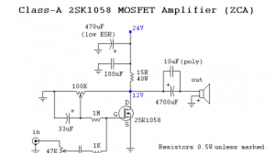
Class-A 2SK1058 MOSFET Amplifier
Undoubtedly, for an amplifier to be called an amplifier, it must contain active ingredients, providing amplification. I've always been fascinated by single-ended tube amplifiers. How is this even possible? Look, one lamp, a couple of resistors and an output transformer. That's why I decided to create an amplifier based on field effect transistor, maintaining the same simplicity of design.One channel unipolar MOSFET suitable for audio, a couple of resistors and capacitors, and of course a powerful, well-filtered power supply. The circuit of such an amplifier is shown in Fig. 1.

Rice. 1: Schematic of a single-ended class A amplifier using a MOSFET
A 2SK1058 field gun from Hitachi was used. This is an N-channel MOSFET. The internal circuit and pinout for 2SK1058 is shown in Fig. 2.

Rice. 2: Hitachi 2SK1058 N-Channel MOSFET
I used Sprague Semiconductor Group capacitors in the input circuits and large electrolytes in the output circuits with a 10 mF polyester capacitor "sandwich". All resistors, unless otherwise noted, are 0.5 Watt. Four 10-watt wirewound resistors act as loads. Beware, these resistors dissipate about 30 watts and become extremely hot even when the amplifier is idle. Yes, this is class A, and low efficiency is the price to pay. It consumes 60 watts to produce approx. 5W! I had to use a powerful and high-quality radiator with effective heat dissipation (0.784 °C/Watt).

Photo 1: Amplifier printed circuit board assembly
Amplifier power supply
The power supply consists of a 160-watt transformer loaded onto a 25-amp rectifier bridge and provides a voltage of approx. 24 Volt. A U-shaped filter (capacitor - inductor - capacitor) is used, consisting of 10,000 Mf electrolytes and 5 Amp chokes with an inductance of 10 mH.
Rice. 3: Power supply diagram

Photo 2: Amplifier assembly
Photo 3: Amplifier assembly, rear view
Amplifier setup
The bias is set by a 1 mΩ resistor and a 100 kΩ potentiometer. Simply set the potentiometer to half the supply voltage at the point where the MOSFET and load resistor connect.Sound
I auditioned my amp with a 12AU7 tube preamp as it provides the clearest sound. I have no idea about this amp's distortion ratios etc. in numbers, I’ll just say that it has accurate sound reproduction and a delicately textured timbre color.To operate the amplifier, highly sensitive, efficient acoustics are required, as it produces approx. 5 Watts RMS (and up to 15 Watts peak, which I clearly observed on the oscilloscope screen). Bass reproduction turned out to be much better than one would expect from such a solution. The amplifier easily drives my 12-inch three-way speakers.
REVIEW OF POWER AMPLIFIERS
POWER AMPLIFIER PAM8403. 2 CHANNELS EACH 3 W.
This power amplifier is distinguished by its miniature size and relatively high output power, since it is a class D amplifier. The PAM8403 chip has two bridge channels providing an output power of 3 W into a 4 Ohm load with a supply voltage of just 5 volts. The oscillation frequency is 260 kHz, which allows you to cover the audio range with a rollover at the edges of only 3 dB.
The circuit diagram of a miniature power amplifier is shown below:
The assembled amplifier board looks very compact and does not require any explanation about the connection:

Judging by the number of orders, these amplifiers are no longer sold by the piece, but by the kilogram...
And of course, a few reviews on this amplifier:
Delivery was on time, the amplifier itself made a splash on my mind, how can such a piece of crap work so well!? I planned to connect it to small speakers, but as it turned out, it pulls great and the speakers are more powerful, a real thing!
I don’t know how it’s 15 watts, but it works clean and loud
I received 2 copies. I've only checked one so far. I loaded the speakers with S-30. Power source 12 volts 4 amperes. Signal source: computer linear output. To the ear, the sound is very decent. I didn’t do any characterization, and it’s not necessary. It couldn't be better to use as an amplifier for a computer, TV or other small portable speaker system. There is no noise when connecting the input with a shielded wire.
the expected result coincided with many reviews, the amplifier operates from a 9 and 12 volt unit, when connected to the equipment, the background disappears, high-quality cords and cables will help... you can load it to full, but a radiator is very necessary, when loaded at 50% everything is ok. I inserted it into an external car speaker, for moments on vacation when connected to a laptop, it works. When listening to music from a smartphone, it began to “swallow” load peaks by more than 80% and reduced the sound by itself,
Amazing amplifier! I used it in my DIY mobile speakers and it works very well! The sound quality is excellent. There is some noise, but it's quiet and you can't hear it when you're playing music, for example. I run it on 2s 7.4 Lipo. it plays loud, but that depends mainly on what speakers you use. Recommended so much!
Delivery took less than a month (I paid extra for delivery). The amplifier is working (don’t attach three padded jackets to it, otherwise it will burn the fuck out, but if you do, listen at the second volume level (if from a phone)). The amplifier is working and for such a price it doesn’t carry too badly (with cooling it can stretch a Vega speaker to middle volume (from the phone). There was no need to contact the seller. From me 5 stars to the seller P.s. I played music from the phone that HAS EQUALIZER FX!!!
Updated reviews
and yes, I soldered it to the aux input, and when you pull out the plug it makes a lot of noise (well, pretty much everywhere), I asked a friend and he said that it should be so, well, I resigned myself, and before pulling out the plug I will turn off the power.
With high-quality food, the sound is very high quality. When the SW jumper is closed, the volume gradually fades to zero, such as the mute function. When opened, the volume smoothly returns back.
The sound quality is worse than I expected
The board does not use the volume control output of the microcircuit. This is not an amplifier, but an interference receiver!
The product was poorly packaged due to which several parts were broken off during transportation. The result is inoperability of the amplifier.
POWER AMPLIFIER FOR TDA2030. 15 W.
Fans of traditional class AB can recommend power amplifiers based on the TDA2030 chip. This amplifier has deservedly gained popularity because this microcircuit Requires a minimum of external components and provides quite high-quality sound.
Please note that most amplifier boards are designed to connect single-supply power. Single boards with a small radiator are not designed to receive maximum power:

Personally, I am more impressed with boards for self-assembly amplifier They are somewhat more expensive and you will have to solder yourself, but this option has much greater versatility. The board of such a power amplifier looks like this:

There are quite a few options for amplifier designs on the TDA2030, ranging from the single-channel options given above to 2.1 systems, where two microcircuits are connected as a bridge for the subwoofer.
For those who have problems purchasing radio components, the most optimal option would be one with an already installed tone control and volume control; this option requires a bipolar power supply:

The amplifier on the TDA2030 chip has the following characteristics:
Maximum output power 18W
Supply voltage 9...24 V (the microcircuit can operate up to 36V supply, but you should check the voltage of the electrolytic capacitors - the Chinese can put capacitors at a voltage of 16V, but this is not enough).
Load resistance 4...8 Ohm
With an output power of up to 10 W, the THD level is no more than 0.1%.
There are also power amplifiers based on the TDA2050, but for some reason they are too expensive.

From personal experience, here are some tips that you can ignore:
There is no need to receive more than 60 W from one chip - it is difficult for it to transfer heat to the radiator.
There is no need to fence bridge and parallel connections - this greatly reduces the reliability of the amplifier.
For those who have collected a couple of copies and are ready to prove with foam at the mouth that everything works, I will tell you that I have collected more than a hundred different versions of amplifiers on the TDA7293 and I can report: everything really works, but in order for it to work RELIABLY it requires additional measures, so for radio amateurs on a budget, it's best not to take risks.
Well, a few reviews:
checked the amplifier, quality product, I advise the sound is good
Great amp! I connected the trans and that's it. Walked for a long time
I installed it in 101 instead of the old transistor ones. for s 90 it’s even enough.
Everything is fine. Delivery on the last day of the first defense. The seller extended it for 40 days. But it wasn't needed. Good quality. I checked everything. The quality is super sound. 5+
I checked everything, everything works, the soldering quality is normal, I just had to wash off the flux
The seller did not send what I ordered. 300 rubles somewhere fucked up... It's a shame. Doesn't respond to SMS
Updated reviews
At first the seller sent the wrong product. After the dispute was closed, I immediately sent my order 1st class to M.O. 6 days. Thank you very much to the seller for your understanding. 5☆☆☆☆☆
They arrived quickly, are already working, fully correspond to the description. Good signet, track layout, no noise, no noise.
One of the two amplifiers arrived in normal condition, the second sparked and smoked and there was a sharp hum in the speaker. I don't recommend it, the quality is crap...
I ordered two amps, one working, the other burned out in a bright flame
The product arrived to be faulty, it was noticed that there was a swollen capacitor, thus a burnt leg of the chip, the seller will return my money, after a dispute
POWER AMPLIFIER MX50. 2 CHANNELS EACH 100 W.
Two 100 W power amplifiers are entirely transistorized without the use of SMD components. Supplied in a self-assembly package. The kit includes printed circuit board and a set of parts. It is extremely rare that a circuit diagram on paper is included - sellers refer to the fact that everything is written on the board. Just in case, below is circuit diagram of this amplifier, which we managed to find:
The power amplifier has two main subgroups, depending on the supplied final stage transistors. One cheaper option uses a pair 2SD1047 - 2SB817 or 2SA1941 - 2SC5198. With a power supply of ±42 V into an 8 Ohm load it is capable of developing 100 W. The second option is equipped with 2SA1295 - 2SC3264. This option is also promised 100 W at 8 Ohms, but if they promise to equip them with ORIGINAL SANKEN, then the collector power of these transistors is 200 W, therefore, with a power supply of ±40 V into a 4 Ohm load, this amplifier can safely deliver 150 W. Of course, this amplifier option is somewhat more expensive. The remaining characteristics of this UMZCH are given below:
Supply voltage: ±15 V to ±45 V
Output Power: 100W8R (±42V)
Voltage gain: 34 times
Input Sensitivity: 1.2V 100W RMS 8 Europe
SNR: more than 98dB
Distortion:< 0.009 THD 1 К ГЦ 10 Вт
Quiescent current 30 mA
Single channel board size: 76mm*73mm
Frankly speaking, so much power is unlikely to be needed for domestic use, but class D power amplifiers deservedly take their place in household appliances, and simplicity and compactness allow you to assemble light and powerful amplifiers audio frequency. The use of a specialized IRS2092 microcircuit makes the assembly and configuration of the amplifier quite simple. For those who do not need 2 kW at home, there are much simpler and cheaper options:
How to determine what transformer power is needed for an amplifier is shown in the video:
Submitted by homemade amplifier works in the 2+1 standard (stereo + subwoofer). It is made on the basis of a popular (and most importantly cheap) microcircuit, which gives an output power of about 30 W per channel with a 4 Ohm AC load resistance and +/-22V power supply. The circuit is suitable for working with any standard audio signal source: mp3 player, smartphone or computer, as it is equipped with a preamplifier with tone controls. The signal to the subwoofer is generated through a second-order low-frequency active filter. Signal components above 200 Hz are cut off, after which the signal is sent to a low-frequency power amplifier. The circuit can be powered with a voltage of no more than +/-25 V.
2.1 audio system amplifier circuit
The input signal is fed to the InP connector - the right channel, and the left channel to InL, passing through a filter high frequencies, consisting of C1 (1uF) and R1 (100k). The values of these elements ensure that the cutoff frequency of this filter is around 1.5 Hz, which effectively cuts out the DC component and very low frequencies. Next, the signal goes to the op-amp amplifier U3A (NE5532), and elements R6 (10k) and R11 (4.7 k) provide signal amplification at a level of about 1.5 (1+4.7 k/10k). Capacitor C6 prevents excitation, while C2 (1uF) decouples preamplifier U3A from a frequency control system built on the operational amplifier U4A (NE5532).
Tone block operation
Frequency adjustment is built in a classical way, elements that make changes to the signal characteristics are in a negative loop feedback U4A chips. Resistance X1 consists of capacitors C17 (4.7 nF), C20 (33nF) and resistor R7 (10k), “half” of potentiometers P1A (100k), P2A (100k) and elements R8 (10k) and R13 (3.3 k ). Resistance X2 consists of capacitors C18 (4.7nF), C21 (33nF), resistor R9 (10k), "half" of potentiometers P1A, P2A and elements R8 and R13. The following figure may help you understand:

When any of the sliders of potentiometers P1A or P2A are moved from their middle position, this will lead to a change in the values of X1 and X2, and, consequently, the gain value becomes different from -1 and begins to depend on frequency. Please note that the values of X1 and X2 always depend on frequency, so it is fixed only in the case of X1=X2.
Potentiometer P1A is responsible for adjusting the low frequencies. For high signal frequencies, capacitors C20 and C21 are conductors, so adjusting with a potentiometer has no effect at these frequencies. Potentiometer P2A allows you to adjust the treble, and thanks to capacitors C17 and C18, it does not affect the bass adjustment. For low frequencies, capacitors C17 and C18 represent an open circuit due to which the potentiometer is disconnected from the circuit and its influence on regulation becomes negligible.
The signal from the output of the tone control unit goes through R12 (4.7 k) to the potentiometer for adjusting the volume P3A (100k) and then to the op amp U5A (NE5532). Elements R14 (15k) and R15 (33k) set the gain to around -2 (-33k/15k). From output U5A, the signal through filter R17 (100P), C3 (1uF) and R4 (100k) enters the input of the UMZCH power amplifier.
The cutoff frequency of the filter for the subwoofer can be calculated using programs or by changing the values of the elements experimentally.
The second channel of the preamplifier works similarly, the passive elements in it that appear are additionally designated by the letter “a”, and the potentiometers and operational amplifiers are marked “B”.
An additional module is a adder and an active low-pass filter made using an operational amplifier U6 (NE5532). The signal isolated in this part of the chain is used after appropriate amplification to drive the subwoofer. The signal from both preamplifier outputs goes through C22-C23 (220nF) and R2-R3 (100k) to the input of U6A. Potentiometer P4 (220k) allows you to adjust the gain in relation to the main volume control P3. P4, R2 and R3 together with U6A form an amplifier with adjustable gain in the range of 0-2.2. The second operational amplifier (U6B) is an active low-pass filter. The values of the elements are selected so that the system operates as a second-order Butterworth filter with a cutoff frequency around 200 Hz. The signal from the filter output through circuit C24 (220nF), R5 (100k) goes to the input of the power amplifier.
ULF power supply

The entire amplifier is powered by a bipolar voltage within 17-25 V. The supply voltage for the operational amplifiers is formed using stabilizers U1 (78L15/L12), U2 (79L15/L12) and filtered using capacitors C4-C5 (100uF) and C7-C8 ( 47uF). In addition, the power supply to each of the four op-amps is smoothed using capacitors C9-C16 (100nF).
Operation of the UMZCH unit
The power amplifier is built on the basis of the popular U7 chip (TDA2050). This is probably the most common audio amplifier operating in class AB. With a total harmonic distortion of 0.5%, it allows you to achieve a power of about 30 W. Capacitor C8 (1uF) cuts off the DC component of the signal and at the same time represents a high-pass filter at the input. R20 (22k) determines the resistance at the input of the power amplifier.
The feedback circuit is resistors R21 (680R) and R22 (22k), changing their ratio leads to a change in gain, and a decrease in R22 or an increase in R21 causes a decrease in gain. In the datasheet of the TDA2050 chip, the manufacturer recommends that it be more than 24 dB. Capacitor C29 (22uF) cuts off the DC component at the amplifier input. Resistor R19 (2.2 Ohm) and capacitor C32 (470nF) prevent the amplifier from self-excitation. The UMZCH power supply is filtered by capacitors C26-C27 (2200uF) and C30-C31 (100nF). The other two channels work similarly.
Assembly
The circuit is soldered onto a common printed circuit board. First of all, you need to solder all the jumpers. Then you can start soldering the resistors. All of them are 0.25 W. Next, attach the sockets for the operational amplifiers. At the very end, place voltage stabilizers, electrolytic capacitors and potentiometers on the board. When installing potentiometers, care should be taken that they are in line - for aesthetic reasons. Metal housings of potentiometers must be connected to ground using wires. This causes shielding of the variable housings, reducing interference and hum alternating current when touching the potentiometer knobs.

All three TDA2050 can be placed on a common heatsink, which will have the potential of the negative power bus. To avoid this, use insulating washers. You must be careful not to short the heatsink to the metal chassis of the amplifier.
It is better to power the amplifier circuit from a transformer with a power of about 100 W and a voltage of 2x16 V, a rectifier and two capacitors that filter the alternating voltage.
Launching and setting up the scheme
When starting up for the first time, do not insert operational amplifiers into the sockets and after turning on the power, check that each socket has the correct supply voltages. Then you can stick them in place. The volume potentiometer should be turned to minimum (all the way to the left), and a signal from an mp3 player or computer should be supplied to the input. The amplifier works well with both speakers speaker systems) with a resistance of 4 and 8 ohms.

TDA2050, TDA2030 or TDA2040 microcircuits operate as output power amplifiers, providing output power of 14, 20 or 30 watts per channel, respectively. Not all amplifier chips have to be the same. You can install those that are weaker as ULF stereo, and the more powerful amplifier leave for the subwoofer.

Voltage stabilizers U1 and U2 provide symmetrical bipolar voltage at a level of +/-15 V. You can successfully use stabilizers for a voltage of 12 V or even 9 V. This will not cause changes in the operation of the preamplifier. This procedure will be necessary if we want to power the amplifier with less voltage than +/- 18 V. The 7815 and 7915 stabilizers may not want to work properly with a low voltage drop. Download PCB files
Discuss the article STEREO AMPLIFIER WITH SUBWOOFER AND LPF
- 05.10.2014
This preamplifier is simple and has good parameters. This circuit is based on the TCA5550, containing a dual amplifier and outputs for volume control and equalization, treble, bass, volume, balance. The circuit consumes very little current. Regulators must be located as close to the chip as possible to reduce interference, interference and noise. Element base R1-2-3-4=100 Kohms C3-4=100nF …
- 16.11.2014
The figure shows the circuit of a simple 2-watt amplifier (stereo). The circuit is easy to assemble and has a low cost. Supply voltage 12 V. Load resistance 8 Ohms. Amplifier circuit PCB drawing (stereo)
- 20.09.2014
Its meaning is different for different hard drive models. Unlike high-level formatting - creating partitions and file structures, low-level formatting means basic layout of disk surfaces. For early model hard drives that were supplied with clean surfaces, such formatting creates only information sectors and can be performed by the hard drive controller under the control of the appropriate program. ...
- 20.09.2014
Voltmeters with an error of more than 4% are classified as indicators. One of these voltmeters is described in this article. The voltmeter-indicator whose circuit is shown in the figure can be used to measure voltages in digital devices with a supply voltage of no more than 5V. LED voltmeter indication with a limit from 1.2 to 4.2V through 0.6V. Rin of the voltmeter...
In the review we study ULF radio designer class AB (2+1) on TDA2030 chips.
Diagram, description of the designer, replacement of microcircuits with TDA2050/LM1875, measurements, possible upgrade.
ULF characteristics
1. Class AB
2. Supply voltage double 12V AC 30W. It is better to use a transformer with a power of 40W or more.
3. Maximum output power 15 Watts per channel
4. Load resistance 4 to 8 Ω
5. Microcircuits are protected from overheating and short circuit.
6. Possibility to connect a passive subwoofer.
7. THD 0.1% or less.
Package


Constructor:

Double Sided PCB (Quality):


Details in detail

Capacitors: 
Potentiometers (all 50 kOhm, linear): 

Accessories: 
TDA2030, NE5532 op amp, 12 V stabilizers.

Radiator for one TDA2030. It is soldered into the board with two legs:


We calculate the area: (3*3+1.5*3*2+0.7*3*6)*2=61.2 cm^2
Transformer for power supply (mine) 40 Watt, two windings of 12 V AC:

ULF circuit
I restored the circuit diagram from the signet. Perhaps I made a mistake somewhere. If anyone notices a mistake, write and I will correct it. 
According to the TDA2030 datasheet, it is recommended to install two capacitors (100 µF electrolyte and 0.1 µF shunting film-ceramic) and two diodes to power each microcircuit: 
They are not here.
Two TDA2030 are installed on the right-left channels, two are included in the bridge and are used for the subwoofer. One preamplifier on the NE5532 works for the general input, the second for the subwoofer.
At the amplifier input there are two 4.7 uF electrolytes, which is not very good. At the input of the channels there is 0.1 µF ceramics. Not good either.
The volume control is after the limit. You can burn opamps with a strong signal.
I’ll write right away that I replaced all Chang electrolytic capacitors with Jamicon 50 V. I installed two 4700 uF*50 V capacitors on the power filter (the maximum capacitance that could fit on the board). I planned to test the amplifier on a 22-25 V power supply, but because of the small radiators I abandoned this idea. In another radiator, I was too lazy to drill 4 holes and solder the capacitors too.
Before completely soldering the amplifier, I decided to assemble only a diode bridge for power supply, power filters and two channels - right and left. I decided not to solder the preamps and amplifier for the subwoofer. Conducted several experiments.
Results of experiments with different capacitors and TDA2030/TDA2050/LM1875 microcircuits
It was connected via an speaker protection board just in case, Mission M51 8 Ohm speaker, DAC Constantine + DAC source (Philips TDA 1545A + Analog Devices 826 opamp) via USB.
First test. Ceramics VS film
First I installed two TDA2030 chips from the kit. On one channel I installed 0.1 µF ceramic capacitors, on the second Wima MKP-4 0.1 µF 250 V. The Wima capacitors fit on the signet without any problems: 
Turned on the power, listened - the result is obvious. With Wima MKP-4 0.1 uF it plays noticeably better. The sound is more detailed. With ceramics it gets a little sandy. If you install a 2 µF film at the ULF input instead of 0.1 µF, the sound improves - the bass plays better.
The sound of TDA2030 chips is quite harsh. HF (cymbals, for example) plays. LF is also ok by ear (especially if you put a 2 µF film at the input).
For further experiments, I removed the ceramics and installed Wima MKP-4 0.1 uF everywhere. 
Next we will test the ULF with different microcircuits. The supply voltage remained the same - 12 V double variable.
Patients: 
From right to left: TDA2030 from the kit, TDA2030 purchased offline (apparently a leftist), TDA2050 purchased offline, LM1875 purchased offline. All microcircuits are interchangeable. The max. differ from each other. supply voltage, power and distortion level.
Close-up:
TDA2030 from the set: 
TDA2030 offline: 
TDA2050 offline: 
LM1875 offline: 
All tests with a 12V transformer.
Second test. TDA2030 from the VS TDA2030 offline set
The sound of the Chinese microcircuits from the kit turned out to be better than those purchased offline. On offline ones the sound is blurry. I liked the Chinese TDA2030 from the set better.
Third test. TDA2030 from set VS TDA2050 offline
The TDA2050 chip is a more powerful chip. If you raise the supply voltage to 22 V, it can output up to 20 W into an 8 Ohm load with a THD of 0.03% at 1 kHz.
Installed. I listened. With this, the TDA2050 plays worse. The sound is somehow “smeared”, sluggish and a little muffled. It’s strange, for some reason people on forums and reviews like the TDA2050 more.
Fourth test. TDA2030 from the VS LM1875 set offline
LM1875 is a more powerful chip. If you raise the supply voltage to 25 V, it can output up to 20 W into an 8 Ohm load with a THD of 0.015% at 1 kHz.
Installed. I listened. The LM1875 has a more detailed sound, a little softer than the TDA2030, but also quite hard, not sluggish.
The result is that the LM1875 won in my tests.
There is a well-known review on YouTube on the Internet on tests of TDA2030, TDA2050, LM1875 microcircuits:
TDA2050 won there. The choice is yours.
Assembled by the designer. All microcircuits, ceramic capacitors from the set. Electrolytes, as I wrote above, were replaced. I installed the opamps on the sockets (they were not included in the kit, I installed my own). I washed the board. Here's what happened:


Controls from right to left: volume control, tone control, subwoofer level. Two resistors are normal (no crackling sound, no sound at min position, channel imbalance, etc.). One (tone control) - crackles a little when rotated. The usual lottery for such cheap parts.
The tone control works on the frequency response like this:

Let's carry out standard voltage measurements in the ULF.
Voltage measurements
AC voltage on the power transformer
One winding: 
Other: 
After diode bridge without load
One polarity: 
Other polarity: 
Under load (amplifier in clipping) 
After stabilizers on the op-amp

Let's connect a load (2 8 Ohm 100 W resistors for each channel and 6 Ohm 100 W for the subwoofer) and measure the constant at the ULF output at the minimum position of the volume control:
Right channel:

Left channel:

Subwoofer:

Let's measure whether the ULF works (supply a 1 kHz signal to the input and look at the output signal with an oscilloscope) and calculate the power of the main channels (8 ohm load). Two thermometers - one for the channels, the second for the subwoofer amplifier:

At the entrance:

At the exit:

A little more and we get clipping:


Pmax=(23.6/2)*(23.6/2)/8=17.4 Watt
Prms=8.7 Watt
Rectangle (turn the tone control all the way to the right - otherwise it will turn out crooked)

Everything is ok here too.
The subwoofer amplifier works like this:
On the input like this:

The output is like this:

If we increase the amplitude of the signal on the subwoofer with the leftmost resistor, we get this:

If it’s even more, then it turns out like this:

When increasing the frequency (for example, up to 400 Hz), we get this:


The subwoofer blew out...
At a temperature of about 110 degrees on my sensors, thermal protection is triggered and the microcircuits are turned off. Small radiators and no airflow.
I also noticed that the built-in op-amp preamp amplifies the sound by only 20%.
Right and left channel tests using RMAA program
Tested at a load of 8 ohms, the maximum output power is about 10 watts, with higher power distortion appears.
Tone control to maximum: 


I connected the amplifier to Mission M51 8 Ohm speakers, DAC Constantine + DAC source (Philips TDA 1545A + Analog Devices 826 opamp) via USB. I connected an old speaker as a subwoofer.
I listened to it on different tracks. The amplifier, in almost stock form, works well. So to speak, “very balanced.” There aren't enough stars, but it's worth its price very well. The truth is a little “sandy” and gives a hard sound. Apparently due to ceramic capacitors. Better than inexpensive D-class (for example, PAM chips)
Here on the site there is a review of a similar (apparently identical in design, but with different parts and board color) amplifier - . The author designed it into a corpus.
What do we have in the end?
He plays for his own money even when basic set The details are quite good. The constructor can be used if you have a couple of speakers and a subwoofer lying around (for example, from a home theater, car speakers, computer speakers, etc.). That's where he belongs. If only stereo, then they sell a bunch of sets in different options on these chips the ULF is only for stereo. If the acoustics are cheap, then
There is no point in upgrading the details. If it’s more expensive, then we change all the 0.1 µF capacitors to a decent film, strengthen the battery in the power supply, change all the pass-through capacitors to 2 µF film, change the microcircuits (ULF and op-amp) and regulators, to increase the power we raise the supply voltage and install a new radiator etc. However, after the upgrade the ULF will cost more than $10.
Thank you for your attention.
The product was provided for writing a review by the store. The review was published in accordance with clause 18 of the Site Rules.
I'm planning to buy +42 Add to favorites I liked the review +40 +74