Rc plane drawings. Radio-controlled airplane from the ceiling
Read also
Which boy doesn't admire structures like airplanes? And do-it-yourself aircraft models made from ceiling tiles are great gift for children interested in aviation. Especially if they took part in assembling the airframe. The article will tell you how to make ceiling tiles simple model airplane.
Aircraft modeling
Model airplane construction is a popular technical sport that is of interest to schoolchildren, students, workers and engineers. At the same time, everyone chooses for themselves a class of aircraft models that suits their interests.
In aircraft modeling there are three fairly large groups of aircraft models, presented in the table:
| Model class | Peculiarities |
|
|
In such models, designer intervention is impossible during flight. All adjustments and settings of the aircraft are completed when it is launched. They can be: - motorless - gliders; - with a simple, very small, internal combustion engine, which is attached to the body with an elastic band. The motors on the models work for a few seconds to throw the light-winged structures up to a hundred meters up, and then they smoothly go down. Timers or special clock mechanisms are used to turn off the engine and switch the steering wheel to planning. |
|
|
With such models, the athlete controls wire threads, which are called cord. The devices fly in a circle with a diameter of approximately 40 meters. The “pilot” is located in its center with the control stick. When you pull the handle towards yourself, the elevator deflects, and the device obediently flies up. And moving the handle away from you causes the model to descend. The devices are:
|
|
|
Controlled remotely, wirelessly. For this purpose, there is a set of radio equipment, which includes a transmitter, in the hands of the operator, and a receiver with steering control mechanisms, mounted on board the model. |


Model aircraft structure
Tip: Before you make an airplane from ceiling tiles, you need to become familiar with its design.
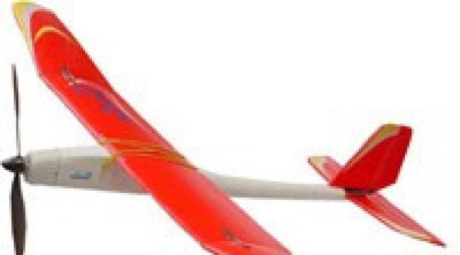
The design of all models is very similar. The main components of the radio-controlled airplane model are shown in the photo.

This:
- Fuselage. This is the basis of the entire model on which the following are mounted:
- bearing structures;
- tail section;
- chassis.
Installed inside:
- engine;
- aircraft control equipment: receiver, steering controls, batteries.
- Wing. Serves to create lifting force. The wing keeps the model in the air.
- Ailerons— control surfaces located at the rear end of the wing and deflected up or down in antiphase. They allow the plane to tilt left and right.
- Tail. It consists of a vertical part - the keel, and a horizontal part - the stabilizer. This device provides stability to the aircraft so that it can fly straight and level without tumbling in the sky, randomly changing the direction of its movement.
The rudder is installed at the rear end of the keel.
- Chassis. Allow the model to take off from the surface and then land on it.
Advice: If there is no landing gear, the model should be launched by hand, and the plane should be landed “on its belly”.
- Engine. Creates the movement of the model, allows it to gain the desired height, and then maintain a given speed.
- Tank. Serves for the fuel needed to run the engine.

- Receiver. Receives the transmitter signal, amplifies it, and processes it. And then it transmits to the steering gears.
- Steering cars. The signal coming from the receiver is converted into moving the model's rudders through the connected rods.
- The receiver and machine are powered from the on-board battery. Usually these are four “finger” elements.
Model selection
Advice: When choosing to make an airplane from ceiling tiles with your own hands, you need to ensure, first of all, that it is reliable to take off and land, and then that it satisfies aesthetic needs.
The aircraft model must have the following properties:
- Be stable: stay in the air well without much input from the pilot.
- It is easy to repair, which is ensured by aircraft models made from ceiling tiles.
- Sufficient strength, but without compromising flight qualities: withstand hard landings and fly well.
We do it ourselves
To work you will need tools and materials:

Making any design, including an aircraft model, with your own hands begins with the development of drawings. To do this, you can use the services of specialists or copy them from websites, print templates on a printer or draw them according to size.

After the printer:
- Printouts on A4 sheet formats are laid out on a flat surface according to serial numbers. The result should be a life-size image of the aircraft elements.
- All the necessary sheets are glued together.
- When gluing sheets without disturbing the dimensions and geometry of the future aircraft.
- Cutting lines are drawn by connecting special crosses drawn at the corners that define the boundaries of the image.
- The resulting airplane drawings from ceiling tiles are combined with structural fragments, glue is applied to the uncut edges of the sheets, and all parts are carefully glued together so that their joints coincide very precisely.

- This way all the fragmented elements of the model are glued together.
- Paper templates are cut out with scissors.
Manufacturing of blanks
Blanks for assembling the aircraft are cut from ceiling tiles using prepared templates.

Tip: To prevent the sheets from moving from the tiles, they must be fixed to the surface of the material with glue. After marking is completed, the glue does not have time to dry and the paper is easily removed without damage for further use.
- To mark a simple part with straight lines, it is enough to pierce all its corners with a needle.
- Remove the stencil and, using a ruler from adjacent puncture points on the tile, cut through the material with the tip of a knife.
- The ruler is shifted to the next adjacent points until the complete cutting of the part is completed.
- A workpiece of complex shape with rounded sides can be completely cut out according to the template.

- It is advisable to mark each part to facilitate its purpose, according to the assembly drawing.
Airplane assembly

Before you start assembling all the parts, it is better to watch the video.
The aircraft assembly technology can be roughly described as follows:
- Double partitions consisting of several parts are glued together, which increases their strength. For example, fuselage partitions.
Tip: For work you should use Titan glue, its price is the most affordable for beginning modelers. It is more convenient to apply glue with a syringe without a needle, using it as a dispenser.
- To ensure that the ends of the cut parts are smooth, they are sanded with sandpaper.
- The side of the fuselage is placed on the table so that the front side is towards the outside of the aircraft. All mounting holes are cut out on it.
- Using this part, the same holes are made on the second half of the fuselage.
- Glue is applied to the glued side of the front compartment partition blank and the part is pressed into place at the installation site. After spreading the composition on the mating part, the workpieces are separated and left for the glue to partially dry for about 30 seconds. The parts are connected again and pressed with force for about 10 seconds.
- When assembling an aircraft, it is necessary, if necessary, to adjust the dimensions of the battery compartment, constantly checking with a square or ruler the perpendicularity of the parts being joined.
- This is how all the fuselage partitions are gradually assembled.

- After installing all the partitions, the second side of the fuselage is glued.
- The nose of the aircraft and the mounting of the frame for the engine are being completed.
- The upper part of the fuselage is installed.
- The tail blanks are glued together. In this case, reinforced tape fittings are immediately laid to fix the rudder and toothpicks for rigidity.

- The gluing is clamped with a board and clamps, which will ensure evenness of gluing.
- The tail is glued into place.
- The verticality of the elements is controlled and strictly maintained.
- The elevator parts are glued together. In this case, a bamboo skewer and tape are placed inside to fix the steering wheel. To ensure reliable gluing of the ceiling halves, the tape can be perforated with holes.
- The elements are compressed with a board and clamps, and left for about a day until the glue dries completely.
- The edges are ground down with sandpaper or a stone at an angle of 45°, which will allow them to not rest against each other when the planes of the model are tilted.
- The wing is assembled, lines are marked on it for gluing stiffeners, ribs, and spars.

- A wooden axle or spar can be made from a wooden ruler 50 centimeters long.
- The spar rail is glued.
- The joint in the center is reinforced with two small slats.
- Foam plastic neurites are glued in.
- Set required form wing plane. To do this, the substrate or ceiling material is rolled onto a piece of pipe.
- Glue is applied to all mating elements and final gluing is performed. While the adhesive composition is setting, the wing is fixed with any in an accessible way: weight, clothespins, tape.

- Small dents caused by clothespins are sanded with sandpaper.
- The cavities in the center of the wing are closed and inserts are glued.
- After the glue has dried, the ailerons are marked. In this case, it is necessary to additionally look at the assembly in the light so as not to get on the partition.
- They are cut through on both sides with a cutter, and the finished aileron is removed.
- Opened cavities are sealed with strips of tiles.
- The ailerons can be glued immediately with reinforced tape or later, before the main fitting of the aircraft model.
- The front part of the wing can be reinforced with reinforced tape.
- The entire model is covered with tape, which serves for beauty, and most importantly gives the structure greater strength, which will allow the product to withstand impacts from falling.
- The adhesive tape is smoothed with a warm iron, which will finally attach it to the ceiling tiles.
- A slot is made in the body of the aircraft into which the wing is installed.
- Servos are installed on the wing. To do this, the elements are applied and outlined with a marker, and a seat is cut out.
- The wires are pulled with a homemade wire hook.
- On the contrary, hogs are installed on the ailerons and connected to the servos with a rigid wire.
- Two servos are installed in the aircraft fuselage, for the rudder and the elevator.
For fixation, it is better to use double-sided tape, glued to all contact areas of the servo. - The elements are installed in place and the supporting walls are additionally glued. The rods are laid from rigid wire to the rudders.
- A frame is made to mount the motor.
- Thin plywood is glued to the motor mounting side; bolts will be screwed into it for fixation.
- The frame for the motor is glued into place.
- The motor driver is mounted in front of the fuselage, and the wires are brought out through the ventilation window and connected.

Car modeling, motor glider, foam planes. Motor installation
- The direction of rotation is checked.
- The fairing is put in place and secured with tape.
- To strengthen the installation site of the wing, it must be secured by gluing plywood or thin shingles.
- The receiver is installed, and all the wires from all the electronics are collected together.
- The bottom of the fuselage is glued, a hatch is cut for mounting the battery.
- The total weight of the model is approximately 450 grams.
- You can fly over a model airplane. The video will show you how to do this.
Assembling airplanes from ceiling tiles is the simplest option, which a novice aviation enthusiast can do if desired. The main condition is to do everything carefully, adhering to the assembly technology, and it is better to take the advice of a specialist.
Here's what we did (video)
Are you looking for aircraft model drawings which one do you need?
Going through blueprints which you dug up on the Internet or took from books or magazines, you think something is wrong……..
This one is too complex, this one is too simple and primitive, and this one is all made of balsa….
And if you are thinking, well, where WHERE can I find the drawing that I need, where is the optimal airplane model or a glider that meets exactly my requirements???
Then you have come to the right place, for which I congratulate you)))
Here you will find EVERYTHING!!!
And if you don’t find it, come back later as the site is constantly updated and supplemented.
The site uses materials from the magazine Modelist-Constructor. All rights to these materials belong to their authors and the Modelist-Konstruktor magazine. The materials on the site are intended for informational purposes only.
And you will definitely find what you need!
So, welcome to not a site full of various drawings of aircraft models
(and not only)
Here you will find:
Airplane models with internal combustion engine Models of aircraft with electric motors
Code aircraft models
Airplane models with radio control
Aircraft models with rubber motor
Helicopter models
Glider models
Paper models aircraft
Kite drawings
Models of rocket planes
Model aircraft drawings presented on the site have various technical solutions, from simple to the most complex, collected here aircraft models from the sixties to the present day. So there is a very large choice here for both beginners and professionals.
And I will constantly update my site with new models of airplanes, helicopters, gliders, and in general I will post here everything that flies. I collected drawings of aircraft models bit by bit from old books and magazines and I hope you will appreciate my work and find a lot of interesting things for yourself here and come back more than once.
Except airplane models I plan to post drawings of aircraft on which you yourself can take off.
These will be:
Gliders
Autogyros
Helicopters
Hang gliders
In general, I have planned to create a portal based on this site in the near future. Where there will be not only aircraft, but also:
Boats
Catamarans
Snowmobiles on tracks and pneumatics
Various velomobiles
Homemade cars
In general, everything that flies in the sky, floats on water, and moves on the ground, and that you can assemble with your own hands. All this will be on my website.
So, here you will learn how to make a kite from the simplest to the more complex.
Many people are skeptical about paper models, but in vain! It's quite interesting.
Drawings of glider models from the simplest to the most complex.
Drawings of line aircraft of all types from training to championship ones. Rubber-mounted aircraft models, this type of aircraft model is very rarely searched for in search engines, I believe that rubber-mounted aircraft models are undeservedly forgotten, take a look there, I’m sure you won’t regret it!
Also here you will find drawings of timer models. radio-controlled airplanes, model helicopters, model airplanes with jet engines, rocket planes, model airplanes with a CO2 engine, with an engine that runs on non-liquefied gas.
Aircraft internal combustion engines (internal combustion engines), how they are designed and how they work, as well as recipes for fuel mixtures.
There is also a section here useful tips. Aircraft modelers are creative people and are constantly inventing, inventing, and improving models. It is these small inventions that this section of the site will be devoted to. I hope you find it interesting and useful.
This article is the story of a person who has never done RC before, who wants to show beginners who have decided to build their first balsa aircraft that there is nothing difficult about it. The article is not instructions for construction, but only a description of one’s own experience. I apologize in advance if I made a mistake in terms somewhere.
Background
It all started with the fact that for my birthday (at 28 years old) I was given radio controlled model an airplane with equipment and the opportunity to take a couple of flying lessons from knowledgeable people.
The instructor was surprised how quickly I got used to the controls (how could he know that I had flown MS a lot Flight Simulator?). It was a training model, and I soon got bored with it; I wanted something more nimble.

I ordered an Extra 330L from the Tower, and, alas, on the first flight I stuck its nose into our planet. The fuselage crumbled right down to the tail, the trailing edge of the left wing console was cracked, the ailerons were torn out, all the plastic parts were cracked and deformed. The frustration knew no bounds! And I wanted to fly.

I laid out the chips and debris on the table and put them together into a puzzle (puzzle, that is). This puzzle was measured and outlined on the computer. At the same time I learned and AutoCAD. Since I was a complete ZERO in aircraft construction and had no idea how and what was attached, I had to compose each part in 3D and combine one with another on the computer. This is how a three-dimensional drawing of this aircraft was created.

I sent complex parts for laser cutting, and cut simple ones with a scalpel myself. The plane was 100% restored. Cracks in plastic parts indicated involvement in the crash.

But then I got tired of the model’s behavior. The dimensions are small (80 cm span), the weight is large (715 g), and the thrust is rather weak (Super Cobalt 400 on 8 banks 1050 mAh with a 7x4 propeller). Experiments with replacing the propeller only reduced flight time from four minutes to three. He turns the barrels, but doesn’t want the loops. Apparently, it's time to want another plane. But not to buy, but to build.
Model selection
I wanted something beautiful, similar to my Extra, but bigger. The main criterion was ease of construction, or at least I had to understand HOW to build by looking at the selected drawing. Internet searches led me to a simple drawing of Ampmaster_jr from Al Eastman.

The drawing is not very detailed, but is accompanied by a description of HOW to build it. I liked this plane. Similar to Extra; the cockpit is almost at the trailing edge of the wing, and this makes it possible to make a huge hood for access to the batteries; designed for an electric motor. Reading the description revealed the fact that the author determined the dimensions of the aircraft by the length of the existing rail for the wing spar. I didn’t have such slats and boards! There were others...
Changing the design to fit existing materials
The drawing was super simple. There were no gaps between control and load-bearing surfaces, shelves for equipment, chassis mounts, etc. It was more of a diagram than a drawing. Reviews and articles by those who have already made this aircraft have revealed its shortcomings. Thus, the CLARK Y profile used (flat at the bottom and convex at the top), although it gave the wing greater lifting force, had a negative effect on acrobatic qualities; zero V of the wing with such a difference between the root and terminal chords affected the increased stall speed; those who made a plane larger than the original spoke of a noticeable improvement in flight performance. I could not miss such important comments and assessed my options for changing the original design.

So. CLARK Y can be easily changed in the program Profile2, it will also generate a set of ribs. The V of the wing is formed by gluing the consoles. What about the sizes? I look at what is the longest monolithic part on the plane: No. 1 - a solid spar of both consoles; No. 2 - balsa board along the fuselage. A solid spar is not suitable (I don’t have such long slats), but a 1 meter long board is just right. I draw this board on top of the drawing, and enlarge the drawing so that the length of the fuselage is equal to one meter. Everything else has also increased, including the thickness of the slats, which already seemed too thick to me - 6 mm. Therefore, I draw my 4 mm slats on top of the drawing; I decided to leave 6 mm on the stabilizer.

So, I got my drawing, and I deleted the layers that contained the original one without a twinge of conscience. I drew my own frames to fit my pre-purchased cockpit (canopy). I also drew the fastening and blowing of the motor, based on technical characteristics previously ordered AXI 2820/10.
I entered the necessary measurements from the received drawing into Real Flight G2. This simulator showed the true behavior of my existing Extra, so I have every reason to trust this program. The plane turned out to be very nimble, but shifting the center of gravity 2 cm forward solved this problem. Motocalc7 I also spoke well about the flight performance with the power plant I chose (40A ESC, 10 cell 4/5 FAUP SANYO, AXI 2820/10, 10x6 – 12x6 Aeronaut propellers).

For a 10x6 propeller, Motocalc7 considered that the model is suitable for performing “almost all aerobatic maneuvers”

Laser cutting
After struggling with thoughts of “Maybe another plane? What if this one doesn’t fly well?” I began to materialize the digital drawing into wood. I identified in the drawing those details that required special precision and accuracy, placed them on the drawn boards and went to cut.

The process of setting up a laser cutter (5 parameters and 100 values each) cost me a lost day, several sheets of burnt balsa, several dozen lost nerve cells from communicating with the owner of the laser machine, who did not understand anything about the settings. But it's done. How I cut plywood for Extra with him before is a mystery. Maybe there were no problems because plywood is more fire-resistant than balsa?
At home I assembled the consoles on the floor to get an idea of what it would look like, and... it happened accidentally. The next day I spoke again with the owner of the laser machine...

Cutting with a scalpel
I had enough patience to cut one rib crookedly. Round holes and protruding supports were especially difficult. Having assessed the time and effort spent, I reconsidered my attitude towards the owner of the laser machine.
It is difficult to cut precise ribs, but it is not difficult to cut straight slats from balsa boards. At the same time, I adapted to cutting off the corners to obtain a triangular joint in the ailerons.

Test on the stabilizer and fin
So I had everything ready to assemble. We have to start, but where? From a simple point of view! From something that can be broken and remade. For me it turned out to be the stabilizer and keel. From photographs on the Internet, I saw that many parts of the model were assembled directly on the drawing laid out and fixed on the table. For greater adhesion of the slats when gluing, it was necessary to make grooves. It is not hard. I made transverse cuts with a scalpel to a depth of 1-2 mm. It turned out that 1 mm is enough for strong gluing, and a 2 mm groove reduces the strength of the rail in this place.

When assembling the stabilizer and fin, I got the hang of gluing with cyacrine and keeping parallels. The tail unit turned out worthy of me breaking it down and making it again. Analysis of errors showed: do not rush, measure seven times and cut evenly, take into account the polymerization rate of cyacrine; sandpaper is a friend of precision.

Wing making
If everything was clear with a flat stabilizer, then how to assemble a non-flat wing, and even with so many fragile parts? I knew two ways: assembly on supports (building tabs); and assembly on slats (jig holes). When generating the ribs in the Profili2 program, I took into account both methods, that is, I marked the holes for my 4x4 mm slats and marked the supports along the trailing edge of the wing, but so that these supports did not protrude into the aileron area. I also made the width of the ailerons based on the presence of triangular balsa boards in cross-section. I took into account the thickness of 1 mm of balsa coating (skin), and made grooves for the spar at 30% of the chord. This place coincided with the highest point of the profile.
An interesting point: the rib that was at the intersection of the wing and the fuselage was imported into AutoCAD, and a cutout was made in the fuselage frame based on it. And the rib itself was supplemented with an area to the bottom of the fuselage and was cut from 4 mm balsa, and not from 1.5 mm, like all other ribs.

Building a wing on slats required an additional structure, which I did not have, and after I also stepped on the structure assembled on slats, breaking 4 ribs, I came to the conclusion that this method was not for me.

The assembly began with the fact that I attached the spar lath to the drawing with pins, marked the places where the ribs should shrink with a marker, made three more duplicates of this marked lath and began shrinking. The exact straight vertical was ensured by the squares previously purchased for this purpose. And I observed the longitudinal deflection of the ribs according to the lines on the drawing.

A drop of super-fast (thin) cyacrine grabbed the joint of the rib with the spar lath so quickly that the support from the previous one was freed for gluing the next rib. After all the ribs were seated on the first spar, I stuck the second rail into the grooves of the ribs on top. Thanks to the ensured verticality of each rib, the grooves coincided with the marked places on the rail. Add a drop of cyacrine to the joint and under the weight to avoid wing twist at this stage.

I cut the trailing edge from a 6 mm balsa sheet with a width equal to the height of the rear edge of the rib, plus 2 mm for the trim. Having attached it to the drawing and marked the joints, I made grooves millimeter deep - the ribs would fit into them. After checking that all the grooves lined up, I built supports that were the height of the table to the bottom of the trailing edge. This height is different at the root and tip chords, since the wing profile is not constant. Having firmly seated the trailing edge on these supports and driven the ribs into the grooves, I dropped a little cyacrine on each joint.
The front edge was glued in the same way and with the same 2 mm sheathing taken into account, only even easier, since I already had experience gluing the rear edge. To avoid twists and deflections, I pinned the entire structure to a straight board and wrapped it with threads, pulling them tightly.
While the wing was drying, I started making the spar seal (webbing). Its role was to create additional bending and torsional strength for the wing. These were jumpers between the upper and lower spar rails. They were cut from 2 mm balsa so that the fibers were vertical.
|
|
|


After the seals were glued in, I left the wing to dry overnight under a weight. Checking for possible deformation did not reveal any signs of twisting or bending, the consoles turned out surprisingly smooth!
When generating by the Profili2 program, it was taken into account that the wing will be covered with a 1 mm layer of balsa. To save balsa, weight and adhere to assembly technology, I cut out pieces that would cover 30% of the front part of the wing. I covered the rest back and cut jumpers connecting both skins along the ribs. The front and rear parts of the skin are equal to the height of the slats.
|
|
|


Fuselage manufacturing
The experience of restoring the Extra 330L gave me some insight into how to build a fuselage.

According to the drawing, I used a scalpel to cut out two side frames from 4 mm balsa.
I glued the frames to one of them in the same way as the ribs to the spar (see above). Next, I easily, like a LEGO constructor, assembled the shell of the hood and battery shelf.
At the moment of gluing in the longitudinal slats, an error in the cutout for them on the oblique frame was discovered. The file helped. Using the same file, I adjusted the cutout for the wing so that the wing and fuselage fit perfectly.

The bottom of the nose was not thought out at the time of drawing the drawing. I made it from the remnants of balsa, lightening it with shaped round holes. Also, on the spot, I figured out a way to snap the hood lid.

Selection of cover color
A long time ago I saw a black plane in some RC magazine. It looked very nice! The black coating reflected the sky, the glare of the sun enhanced the effect of the black enamel. But the position in the sky of an all-black plane would be difficult to discern. So I armed myself Photoshop"om 7, and at random I picked out the yellow stickers on a photograph of an amplifier that someone had already made. The result was a kind of German color scheme. In order to understand in flight where the belly and where the back of the aircraft are, I tried to make them as distinguishable as possible.

|
|
|


Installation of equipment
Since the aircraft itself was built according to the principle “what we have, we build from,” there was also not much to choose from. For ailerons according to HS-81, for everything else HS-55. The doubt crept into my head whether the HS-55 alone would be able to cope with the elevator, given the area of the rudder, the weight of the aircraft and the length of the arm. I had to extend the rod from the keel machine to the second half of the elevator, and make a separate socket for the new rudder machine with the ability to use pull-pull. On the transmitter I made a mix of 2 and 7 channels for the elevator.
I found out at a local store that machine wires up to one meter in length do not require any noise or interference suppressors, so I simply soldered in extension wires.
|
|
|


tight fitting
The special iron purchased for this purpose has proven itself to be easy to use. Before this, I tried using a home iron - it was cheap, but inconvenient. I started the trim from the hood, and the first time it didn’t work. I tore off the wrinkled covering and then followed the instructions that came with the film - I pinned the flap at the corners, then along the edges, and then glued everything else. I fought wrinkles with high temperatures. After I felt the behavior of the film during shrinkage, I boldly began covering the wings and fuselage. The entire fitting took a little over three hours.
And the covered plane waited for the motor and batteries for two months...

Test flight
Finally the wait!
The motor is installed, the batteries are pumped up and charged, and traction has been tested at home.

It was very scary to break my creation on the first flight, so I double-checked everything: all the rudder costs, rudder directions, the center of gravity, the rigidity of the batteries, wing and landing gear, I even shook the model to make sure it was strong.

I entrusted the first flight to a local champion. He pressed full throttle, the model took off, took off about two meters from the ground and confidently gained altitude. The pilot made a semicircle, flew in a straight line, made a roll, a loop, turned the plane on its back and flew like that for two circles, joking that I supposedly forgot to glue the landing gear... When I asked why he didn’t trim the model, he said that there was no trimming not required. What a joy! First flight - and it flies perfectly!
After a soft landing at our feet, the pilot advised us to engage the exponential control on all rudders, especially the elevator, and gave a lot of pleasant feedback about the model. Then my hands, trembling with excitement, took hold of the remote control. On the fourth battery I was already turning the plane as I wanted. The only thing that didn’t work was to fly vertically upward indefinitely, but I didn’t expect that. Subsequent flights were more confident and full of acrobatics. With wasteful use of gas, the flight time was more than seven minutes. With four batteries and the ability to charge two at a time, I can stay on the flight deck all day!
We count the costs
| Balsa | ~30 USD |
|---|---|
| Laser cutting | it cost me free |
| Oracover film | 20 USD |
| AXI-2820/10 | 90 USD |
| Propeller with collet and spinner | ~20 USD |
| MM 40-3p regulator | 110 USD |
| 10 cells 4/5 FAUP pack | 65 USD |
| Charger SuperNova 250S | 105 USD |
| 5 servos | ~100 USD |
| Receiver 7 channels | ~ 40 USD |
| Eclipse7 transmitter | ~300 USD |
| Other parts (cabin, chassis, hogs, etc.) | ~50 USD |
| Time for modeling and manufacturing | two weeks |
For some it is expensive. But if the plane crashes, then only the balsa and film are lost; the rest of the equipment, as a rule, is not damaged and can be used in another plane.
Error Analysis
Despite good result, namely: a beautiful plane, flies well, impresses DVSnikov, there are several points that I would criticize.
The first is the design stage in AutoCAD. Even at this stage, it is necessary to think through the mounting of the cars, hood latches, identify the distribution of masses, and pay a lot of attention to the details. But I didn’t do this.
Secondly, this is the assembly stage: I cut the stabilizer with a scalpel, not a laser, so it turned out to be far from ideal.
Third, this is the tightening stage. Still, it was necessary to glue the black overlapping the yellow, and not vice versa.
Fourth, this is decision-making: do not believe evil tongues that such a plane will not fly. He's flying!
Conclusion
The flight results exceeded even optimistic expectations. The plane behaved even more stable than its virtual clone in Real Flight G2.
|
|
|


The construction turned out to be not as difficult as I imagined at the beginning. I was told that this is not the plane that should be built first, but I believe that if a person is confident in his capabilities, then he can build this plane as the first and even complicate it!