Connecting the reset button to the motherboard. Connecting the front panel to the computer motherboard
Read also
The motherboard is the most important component of a computer, because it is where the rest of the hardware is connected. In some cases, it refuses to start when the power button is pressed. Today we will tell you how to act in such a situation.
The lack of response to the power supply indicates, first of all, a mechanical failure of either the button itself or one of the board elements. To exclude the latter, diagnose this component using the methods described in the article below.
Having ruled out the breakdown of the board, you should examine the power supply: the failure of this element can also make it impossible to turn on the computer from the button. The guide below will help you with this.
If the board and PSU are in good condition, the problem is most likely in the power button itself. As a rule, its design is quite simple, and, as a result, reliable. However, the button, like any other mechanical element, can also fail. The instructions below will help you troubleshoot the issue.
Method 1: Power button manipulation
A defective power button must be replaced. If this option is not available, it is possible to turn on the computer without it: you need to supply power by closing the contacts or connect the Reset button instead of Power. This method is quite difficult for a beginner, however experienced user it will help you troubleshoot.

The disadvantages of such solutions to the problem are obvious. First, both the closure of contacts and the connection "Reset" create a lot of inconvenience. Secondly, actions require certain skills from the user that beginners do not have.
Method 2: Keyboard
The computer keyboard can be used for more than just text input or control operating system, but is also capable of taking over the functions of turning on the motherboard.
Before proceeding with the procedure, make sure that your computer has a PS / 2 connector, such as in the image below.
Of course, your keyboard must be connected to this connector - with USB keyboards this way won't work.

As you can see, even such a seemingly difficult problem is very easy to fix. In addition, using this procedure, you can connect the power button to motherboard. Finally, we remind you that if you think that you do not have enough knowledge or experience to carry out the manipulations described above, contact the service center!
How to connect the motherboard to the front panel, which contains all the main buttons and indicators?
The procedure for attaching the motherboard to the front panel is a standard computer assembly process.
Before starting the connection process, you should study in detail the appearance of each element of the front panel of the computer case and the queue for connecting it to the motherboard.
Remember! If you connect elements to the main system board in the wrong order, some of them may not work or work incorrectly.
Learning the names of all the elements and their location is quite simple. All of them have a certain marking, name and appearance.
Connecting all buttons and status indicators
On any case there are indicators of the status of the computer, LEDs, buttons, drives. Other elements may also be present.
On the computer motherboard, there is a separate block for connecting LED bulbs (indicate the on state) and buttons.
Components are connected to this block using four separate connectors.
Their appearance is shown in the figure below. They look the same on all computers, but the phrases that are written on them may differ (but they mean the same thing).
Connectors are painted in different colors.
Yellow is for connecting the power button, blue is for the system status diode (lights up when the system is rebooted).
The green connector connects to the computer motherboard the indicator light for pressing the power button (after pressing the power key, the corresponding light turns green).
Red - power button cable.
The connector that links the speaker to the chassis can also be colored yellow.
This speaker makes beeping sounds when the computer is turned on, during system error detection, or when connected to a wireless network.
All connectors connect to one specific motherboard port. Typically, this port is located on the lower right side of the system's main board.
Computer parts manufacturers refer to this port as PANEL and its variations (F_PANEL).
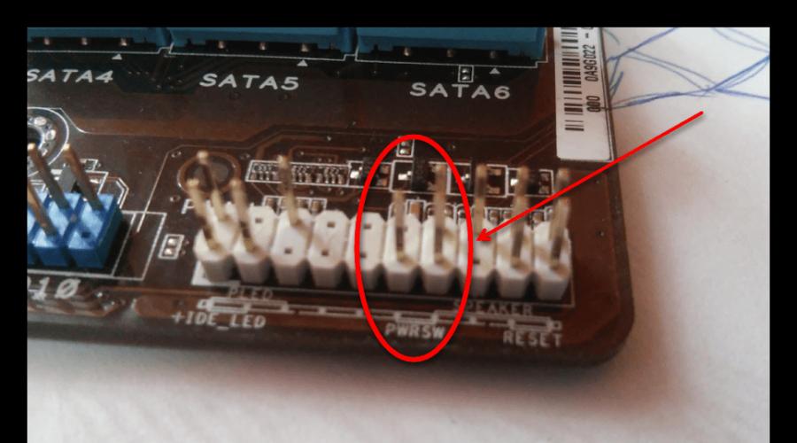
Absolutely every motherboard has signatures that indicate what and where to connect. The figure below shows the required port on the board.
The arrows indicate where to connect each of the connectors.

On the main board, you can often find a separate connector for connecting a speaker, which reacts to errors in the BIOS and in the computer hardware.
The location of the connector is shown in the figure:

After connecting the block with buttons and diodes, you can start connecting all the front USB inputs, as well as audio outputs.
The process of connecting the front panel of the system unit case
Appearance connectors for USB and sound practically does not differ from those connectors that were described above in the article.
However, unlike the previous connector wires, they are connected together.
Each connector has a name (respectively USB and HD AUDIO). The appearance of the wires is shown in the figure below:

The connector for connecting these connectors on the motherboard is located at its bottom and, as a rule, is signed with the names F_USB1 or F_USB2.
There can be more than two connectors for connection (newer versions of motherboards).
It doesn't matter which wire you connect to.
All inputs are absolutely identical, the order of their connection does not affect the operation of the front panel components of the computer.
It is also impossible to make a mistake with the correct side of the connector.
The USB connector can only be connected in one direction.
Follow instructions:
- Find a connector called F_USB;
- Locate the corresponding connectors on the motherboard. Their location is indicated in the figure;

- Connect the connectors to any of the connectors on the board.
Note! If your computer case indicates that you are using USB version 3.0, you need to connect the connector only to a specific connector. To which one, you can read in the instructions that come with the motherboard.
Connecting the Front Soundbar to the Main Board
Now you need to connect sound devices to the motherboard. All actions are almost the same as connecting USB connectors.
Connectors are also connected together with each other.
Thus, you can accurately connect all the components to the computer motherboard.
On most motherboards, all audio connectors are located near USB connectors. The approximate location of the ports can be seen in the figure below:

Most often, audio connectors are signed as AC 97.
Good day, dear readers. As you understood from the title, we will talk about connecting the front panel and motherboard connectors to the case or vice versa.
This is an article that is a small addition to the once written material on assembling a computer under the same name “Assembling a computer with our own hands” or “What is what in a computer, part 2″.
We will talk about a small missed, but important element - connecting connectors (all kinds of buttons, lights, etc.) of the front panel.
Go.
Front panel connection - connection instructions
On the front panel of the system unit, there are usually power buttons and a manual reset of the computer. They also need to be properly connected to. Connection cables are usually made in the form of pins (see above for what pins are).
They look something like this (clickable):

Power SW - power button cable; Power LED + - - power indicator (bulb) cables; HDD LED - loading indicator cable (the same light that usually blinks); RESET SW - reset button cable.
Proper connection of the front panel connection is also important, because without this the computer simply will not turn on.
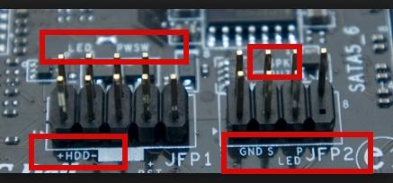
Each motherboard has a so-called Front panel contact block or F-Panel for short. Usually it is located in the lower right corner of the board, but there are exceptions. This is how it looks like:

Connecting the connection of the front panel and its pins is carried out manually and for this there are definitely tips in the accompanying documents to the motherboard.

If there are documents, then it is not difficult to connect the pins. If not, there are hints on the motherboard itself around or next to the F-Panel. If you are lucky many times, then the motherboard comes with the following adapter:

In which you simply stick, as shown above, the connectors themselves, and then this adapter to the motherboard and everything turns out quickly and simply. But not everyone is so lucky, and you probably got here because you are trying to connect everything for an already former (and not new) motherboard.
What else is worth knowing
In addition, on the front panel of the system unit there are sometimes USB interface connectors (usually a couple of them) and ports for connecting headphones / speakers and a microphone. It looks something like this:

Cable pins for connecting these external USB ports inside the system unit look like this:

They are connected to the pin blocks on the motherboard, which are called F-USB1 and F-USB2, respectively (they may not look exactly the same in color and location as in the screenshot below, but everything is the same in shape and number / location of pins):

The ports for connecting external audio inputs look approximately the same - only the position / number of pins differs, so connecting the front panel in this regard is not a very difficult task.
It’s easy to connect them (they simply won’t fit into other pin blocks). But for them, there are also hints in the accompanying documents for the motherboard:

Actually, everything and nothing complicated in this.
What to do if the documentation for the motherboard has not been preserved
Or take a magnifying glass and carefully study the connector mentioned above for connecting on the computer motherboard:
Usually it is at least somehow, but symbolically signed, since from the second or third time you can guess what is there and connect everything correctly. The wires are connected, as a rule, with an inscription on themselves:

Occasionally, the second row (far) looks the other way with inscriptions, but this is quite rare. One way or another, as I wrote above, not from the first, so from the second time - guess :)
If you can’t see anything (whether your eyesight is weak or the inscriptions are poorly spelled out), then open the motherboard manufacturer’s website and look for the “Support” section (or something like that), where you can usually download the instructions from the motherboard, where it is always described connection.

If you couldn’t find it on the manufacturer’s website, then you can find it on the Internet by querying “board name” + the word manual, with a minimum knowledge of English, you will definitely find a place to download, and there you can open, look and connect.
Afterword
If you have any questions or additions, write in the comments or with the help. I would be happy to help and just listen to you.
PS : The images shown are for illustration purposes only. No ads.
PS2: The article was written by a person who lives on the net under the nickname (friend and assistant of the project). For which many thanks to him.
The power supply is an integral part of any personal computer. Thanks to the block, electricity is conducted to the motherboard, the central processor and any other peripherals.
When installing this device in no case do not connect it to the power supply.
To connect you will need a cable with connector 24pin, however, older models use 20+4 pin. Such a connector is always included with your power supply, and you do not need to buy it separately.
Standard 24 pin connector

Connector 20+4 pin
This cable has a small latch on one side, which allows you to correctly position the connector when connected to the motherboard.
When connecting the module do not do it apply great force so as not to damage any of the devices. However, it is necessary to achieve a tight fit in the socket on the board, as well as make sure that the latch clicks and is securely fastened.
 Fixed 24 pin connector
 Thus, we connected two main devices together, which will allow us to supply power to the motherboard.
Next, you need to supply power to CPU. Behind this function answers 4 pinconnector. For more powerful processors used 8 pinconnector.

Standard 4 pin connector

8 pin connector for more powerful processors
Connecting this module likewise the contacts mentioned above. Plug must be plugged into socket click clamp that ensures a tight fit of the cable.
Thus, we have established the supply of electricity not only to the motherboard, but also to the central processing unit.
Connecting the front connectors
Buttons are usually present on standard system units. food And reboot personal computer, as well as indicators(bulbs). Their connection to the motherboard is carried out after 1-2 pins connectors that need to be connected correctly. These cables have hints, in the form of inscriptions that allow you to understand what each of the connectors is responsible for. To connect them, you need to find a special panel on the motherboard ( F— panel) and connect the cables, correctly arranging them.

f-panel

Pins responsible for the front connectors of the system unit
- Power SW responsible for the power button of your personal computer
- Reset SW for the reset button
- Power LED- these are the power indicator cables (lights that light up when the computer is turned on)
- D.D.LED– HDD loading indicator cable
When installing these cables, you must adhere to strict order . Each pin should be connected so that the inscription looks up. The location of their connection is often indicated in the tips near the F-panel on the motherboard itself. However, for convenience, it is recommended to use following scheme.
 Connector layout
 It is also worth paying attention to the fact that the connectors power LED divided into two 1 pin cables and subdivided into "+" and "-". It is necessary to arrange these pins so that as indicated in the diagram.
With the standard F-panel layout, the result should look like this:
 Final result
 However, this process is not over.
Often, on the front panel of the system unit there are also interface connectorsUSB And 3.5mm ports to connect audio devices and microphone.
 USB and 3.5 mm connectors
 There are also hints on these cables, and it’s quite hard to make a mistake, because. also present on the motherboard. signatures near the sockets required for connection.

Pins for 3.5mm jacks

Pin responsible for the USB connector

Connection sockets
How to connect video cards
Before installing this device, you need to determine in which port it should be installed.
Video card connectors are three types:
- Standard AGP(Obsolete and no longer used in modern models)
- Standard PCI(Used by previous generation cards)
- Standard PCI— Express(Used by modern graphics cards)
Because standard AGP already outdated, we will consider only connectors PCI And PCI— Express.

PCI-Express slot

AGP connector
It should be noted that connecting a video card with an AGP connector to a PCI-Express slot and vice versa - impossible. These standards differ not only in size, but also in cutout.
 Comparison of AGP and PCI-Express standards
 Having dealt with the type of port to which you need to connect the video card, you can proceed with the installation.
To get started you will need remove the plug from the back of your system unit. This can be done by unscrewing the fixing screw.
 Stubs
Stubs After the plugs have been removed, you need to carefully insert video card to the port you defined earlier. It is not necessary to apply force to the connection, the card enters the slot very easily, and the latch will help to make sure that it is installed correctly and tightly, which will emit click. Also, when connected, the interface panel of the video card should face back panel your case - to the place where the plugs were previously.
 Installing the video card in the slot
 After the video card is firmly seated in the slot, and the latch is fully latched, you need to fix its bolts, which remained from the removed plug. It happens like this:
 Fixing the video card with bolts
 Make sure the card is secure and does not stagger in the nest.
After that, you need to swipe to this device power supply.

Video card power connectors

Video card power
The video card power cables are included in the complete set on expensive models. On cheaper, such cables not included. Therefore, you will need to check if there is such a connector on power supply.
Module needed connect to the power socket on the video card. This is done in the same way as connecting the power connectors of the motherboard and the central processor.
The connection is made up to the moment clicks latch. The other end of the cable is connected to the power supply.
Connecting a sound card
Installing an internal sound card is very similar to video card connection. The difference is only in ports, to which connect this device.

Connecting a sound card to the wrong port will be difficult and even more likely impossible. The length of the PCI and PCI-Express x1 slots is cardinally different.
It is also necessary to remove plug from the back wall of the system unit, and then carefully insert the sound card into the desired port. Most motherboards do not have a latch on these connectors, so there will be no click when tightly connected.
After the actions taken, fix sound card with the fixing bolt left after the removed cover. It is recommended to make sure that sound card connected securely and does not wobble in the socket.
Additional power supply is not required (except for professional models).
Drive connection
Before installing this device, you must determine the type connections.

The drive must be placed in a specially designated place for it inside the system unit. By default, this is the upper front part of the case.
Connecting a drive with an IDE interface type
After installing the drive inside the case, you need to to plug power cable and data cable to it.

Data loop

Drive power cable
The power cable is connected in the same way as the CPU and video card power connectors.
Plume data must be carefully, without applying force, inserted into the connector on the back of the drive.
 Connecting the data cable to the drive
 The other end of the cable must be connected to one of the channels IDE controller on the board.
 Location of IDE controllers
 - Under the number 1 in the figure is shown IDEcontroller, which can accommodate two devices with jumpers Master And slave.
- Under number 2, the IDE controller may also include two devices. In master mode, this is the Master jumper, and in slave mode, this is Slave.
- Number 3 is the controller floppy drive.
To select the necessary jumper (Master or Slave), you need to inspect the drive case. The position of the jumper is indicated there.
Left fix drive to system unit 4 bolts included.
Connecting a drive with a SATA interface type
Installing a SATA type drive (used by modern devices) identical installing an IDE drive. The difference lies in the connector that needs to be connected to the drive and the motherboard.

SATA cable

SATA ports
It is worth noting that the power connector for modern drives is different from the power cable mentioned earlier. Below is a photo of the connection SATA-cable and a new power cable to the drive.
 Left - power cable, right - SATA
 It also happens that the drive has an old power connector, but it uses the type SATA interface. Such drives are used very rarely, but they do exist.
All that's left is to fix the drive in the case with 4 bolts and check that it is securely fixed.