What is a transformer and how it works. Working principle of a voltage transformer
Read also
Step-up transformers are power structures designed for installation in electrical household and industrial circuits. The installation changes the voltage upward. How step-up transformers work, where such installations are used, needs to be considered in more detail.
Operation
To understand what voltage-increasing transformers are, you need to understand the principle of operation. The equipment is manufactured for power plants whose design schemes belong to the pass-through category.
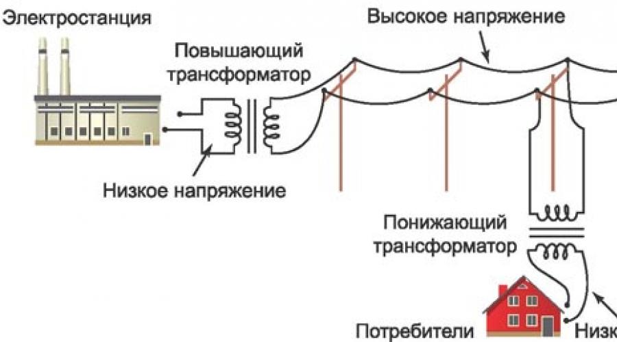
A step-up transformer at power plants is used to provide populated areas and other objects with current with certain technical indicators. Without a converter, the high voltage gradually decreases along its path. The end consumer would receive insufficient electricity. At the final power plant in the circuit, thanks to this installation, electricity of the appropriate value is received. The consumer receives a network voltage of up to 220 V. Industrial networks are provided with up to 380 V.

A diagram showing the operation of a transformer in a line includes several elements. The generator at the power plant produces 12 kV electricity. It is supplied through wires to step-up substations. A transformer apparatus is installed here, designed to increase the indicator in the line to 400 kV.
From the substation, electricity enters the high-voltage line. Next, the energy enters the step-down substation. Here it drops to 12 kV.

Transformers with a reverse operating principle direct the current to the low-voltage transmission line. At the end, another step-down unit is installed. From it, electricity with an indicator of 220 V is supplied to houses, apartments, etc.
Device principle
When considering how a voltage-increasing transformer works, you need to delve into the basic principles of the design. The basis for the operation of a transformer is the mechanism of electromagnetic induction. The metal core is in an insulating environment. The circuit includes two coils. The number of windings is not the same. Coils with more turns in the first circuit than in the second can increase the indicator.
AC voltage is supplied to the primary circuit. For example, this is a current in the network of 110 (100) V. A magnetic field appears. Its strength increases with the correct ratio of windings in the core. When electricity passes through the second winding in the step-up transformer, a current with a certain indicator appears. For example, an indicator of the characteristics of a 220 V network is provided.
In this case, the frequency remains the same. For admission direct current A converter is installed into the circuit in the power supply line. This device can be used in boost-type equipment. The device is capable of working not only to change voltage, but also frequency. Certain equipment is powered by direct current.
Varieties
- Autotransformer. It has one combined winding.
- Power. The most common type among devices that increase voltage.
- Anti-resonant. Has a closed design. Due to their special operating principle, they have compact dimensions.
- Grounded. The windings are connected in a star or zigzag pattern.
- Peak transformers. Separate direct and alternating current.
- Household. The improvement in the characteristics of electricity during the operation of a transformer is carried out in a small range. They help eliminate interference in the household network, protect equipment from surges, low and high electricity.
The presented designs differ in power and technical characteristics.
Other types
In accordance with the performance characteristics, the presented equipment differs in several ways. Depending on the number of circuits, there are single-phase (domestic) and three-phase (industrial) designs.
Various substances are used as a cooling system. There are oil and dry varieties. In the first case, the equipment costs less. Oil is a flammable substance. When used, high-quality protection against accidents is provided. Dry units are filled with a non-flammable substance. They are more expensive, but the requirements for their installation are fair.
![]()
Coolant circulation in the system can be forced or natural. There are designs that combine these methods. The variety of types allows everyone to choose the optimal type of device.
Marking
Manufacturers have developed special markings for the equipment presented. This allows consumers and inspectors to easily identify the type of equipment.
![]()
IN general view the designation looks like this - TM/N – X, Where:
- T – device type designation;
- M – unit power specified by the manufacturer, kVA;
- N – voltage class on the winding side high voltage(VN);
- X – climatic characteristic that determines the features of placement in accordance with GOST 15150.
The marking may include other characteristics. A plate indicating the parameters of the device is installed on its body. When installing equipment, the marked information must be in a place accessible for visual inspection. Read more about transformer markings.
Repair and service
A transformer is a complex piece of equipment. It will need to be serviced periodically and. It is recommended to entrust this work to professionals. Only a person with appropriate training has the right to carry out such work.
With an increased heating rate and the presence of noise, it is necessary to rewind the transformer circuits. This procedure can only be performed by an unqualified specialist with a minimum level of knowledge in the field of electrical engineering.
![]()
The device has a magnetic drive. It is common to coils. The first circuit is responsible for reducing, and the second circuit is responsible for increasing electricity in the network. Inspection of the transformer is carried out using a certain technology.
Examination
First, a visual inspection of the block is carried out. If overheating is observed during operation, deformations, irregularities, and swelling of the insulation appear on the surface. If the inspection does not reveal any deviations, you need to find the input and output of the device. The first of them is connected to the first coil. This is where a magnetic field appears when electricity is supplied. The output is connected to the secondary winding.
The output signal is filtered. This indicator needs to be measured. The collapsible parts of the housing structure are removed. You need to gain access to the microcircuits. This will allow you to measure the voltage with a multimeter. In this case, you will need to take into account the nominal indicators. If the measurement result is less than 80% of the value specified by the manufacturer, the primary circuit is not functioning correctly.
![]()
The first coil is disconnected from the device. It no longer receives electricity. Then the secondary circuit is checked. In the absence of filtration, power is used from measuring instrument. If there is no normal voltage in the system, the equipment requires repair.
After checking, if the component elements are in good condition, the structure is assembled in the reverse order. If necessary, the unit is repaired.
Interesting video: How does a transformer work?
Having examined the features and operating principles of step-up transformers, one can evaluate their importance in power lines. The use of such equipment improves the quality of electricity in household and industrial networks. It is installed everywhere. The presented types of installations are in high demand today.
Transformer, a device that transfers electrical energy from one part of a circuit to another through magnetic induction and, as a rule, by changing the magnitude of the voltage. Transformers only work with AC electric shock(AC).
Transformers are important in power distribution. They increase the voltage generated in power plants to high values for the purpose of efficient transmission of electricity. Other transformers reduce this voltage at points of consumption.
Many household appliances are equipped with transformers in order to increase or decrease the voltage coming from the home electrical network as needed. For example, for a TV and an audio amplifier to work, an increase in voltage is necessary, and for operation doorbell or thermostat low voltage.
How does a transformer work?
Typically, a simple transformer consists of two coils wound insulated wire. In most transformers, the wires are wound around a rod of iron called a core.
One of the windings, also called the primary winding, is connected to the source alternating current, which in turn leads to the appearance of a constantly alternating magnetic field around the winding. This alternating magnetic field, in turn, creates an alternating current in the other winding (the secondary winding).
The value, defined as the ratio of the number of turns in the primary winding to the number of turns in the secondary winding, determines the scale of the decrease or increase in voltage in the secondary winding. This value is also called the transformation coefficient.
For example, if a transformer has 3 turns in the primary winding and 6 turns in the secondary winding, then the voltage in the secondary winding will be 2 times greater than in the primary. Such a transformer is called a step-up transformer.
![]()
And on the contrary, if there are 6 turns in the primary winding and 3 turns in the secondary, then the voltage removed from the secondary winding will be 2 times lower than in the primary winding. This type of transformer is called a step-down transformer.
![]()
It should also be borne in mind that the ratio of current in both coils is inversely related to the ratio of their voltages. Thus, the electrical power (voltage times current) is the same in both coils.
The impedance (resistance to alternating current flow) of the primary coil depends on the impedance of the secondary circuit and the transformation ratio. With the correct ratio of transformer turns, you can achieve almost the same resistance of both circuits.
Matched impedances are important in stereo systems and other electronic systems, therefore this allows the maximum value of energy to be transferred from one block of the circuit to another.
The operating principle of a transformer is related to the principle of electromagnetic induction. The current entering the primary winding creates a magnetic flux in the magnetic circuit.
The operation of a transformer is based on the phenomenon of electromagnetic induction. One of the windings, called the primary winding, is supplied with voltage from an external source. The alternating current flowing through the primary winding creates an alternating magnetic flux in the magnetic core, phase-shifted, with a sinusoidal current, by 90° relative to the current in the primary winding. As a result of electromagnetic induction, an alternating magnetic flux in the magnetic circuit creates in all windings, including the primary, an induction emf proportional to the first derivative of the magnetic flux, with a sinusoidal current shifted by 90° relative to the magnetic flux. When the secondary windings are not connected to anything (no-load mode), the induced emf in the primary winding almost completely compensates for the voltage of the power source, so the current through the primary winding is small and is determined mainly by its inductive reactance. The induction voltage on the secondary windings in no-load mode is determined by the ratio of the number of turns of the corresponding winding w2 to the number of turns of the primary winding w1: U2=U1w2/w1.
When the secondary winding is connected to a load, current begins to flow through it. This current also creates a magnetic flux in the magnetic circuit, and it is directed opposite to the magnetic flux created by the primary winding. As a result, the compensation of the induced emf and the emf of the power source is disrupted in the primary winding, which leads to an increase in the current in the primary winding until the magnetic flux reaches almost the same value. In this mode, the ratio of the currents of the primary and secondary windings is equal to the inverse ratio of the number of turns of the windings (I1=I2w2/w1), the voltage ratio, to a first approximation, also remains the same.
Schematically, the above can be depicted as follows:
U1 > I1 > I1w1 > Ф > ε2 > I2.
The magnetic flux in the magnetic core of the transformer is shifted in phase with respect to the current in the primary winding by 90°. The emf in the secondary winding is proportional to the first derivative of the magnetic flux. For sine signals, the first derivative of sine is cosine, and the phase shift between sine and cosine is 90°. As a result, when the windings are turned on in agreement, the transformer shifts the phase by approximately 180°. When the windings are connected in opposite directions, an additional phase shift of 180° is added and the total phase shift by the transformer is approximately 360°.
Idle experience
To test the transformer, use the open-circuit test and the short-circuit test.
During the no-load test of a transformer, its secondary winding is open and there is no current in this winding (/2-0).
If the primary winding of the transformer is connected to the network of an alternating current electrical energy source, then the no-load current I0 will flow in this winding, which is a small value compared to the rated current of the transformer. In high-power transformers, the no-load current can reach values of the order of 5-10% rated current. In low-power transformers, this current reaches 25-30% of the rated current. The no-load current I0 creates a magnetic flux in the transformer magnetic circuit. To excite the magnetic flux, the transformer consumes reactive power from the network. As for the active power consumed by the transformer during idle operation, it is spent to cover power losses in the magnetic circuit caused by hysteresis and eddy currents.
Since the reactive power during no-load operation of the transformer is much greater than the active power, its power factor cos φ is very small and is usually equal to 0.2-0.3.
In order to independently increase the operating efficiency of many devices and the voltage at home, electrical network, regulating devices are often used. In this regard, we propose to consider the operating principle of a step-down, step-up, pulse, Tesla current transformer, as well as an autotransformer.
Operating principle and classification of transformers
The operating principle of an instrument transformer (as well as an isolation transformer) is very simple. It obeys Faraday's law of electromagnetic induction. In fact, mutual induction between two or more windings is responsible for the transformation actions in an electrical transformer.
In accordance with this, Faraday's law states: “the rate of change of flux linkage with time is directly proportional to the induced emf in the conductor or coil.”
Basics of Transformer Theory
Let's say we have a transformer with one winding, which is connected to an alternating electrical current source. Alternating current through the winding produces a constantly changing flux that surrounds the coil. If any other winding is close to the previous one, a certain part of the flux is connected to it. This flux is constantly changing in amplitude and direction, but in these cases there must be a change in flux linkage to the second winding or windings.
According to Faraday's law of electromagnetic induction, there must be an emf that is induced once per second. If the circuit of the last winding is closed, then an electric current must pass through it. This is the simplest operating principle of an electrical power or welding transformer and is the basic operating principle of a transformer.
Power transformer circuitWhenever we use the movement of alternating current to an electrical coil, a flow of energy surrounds that winding. The current flow will be uneven and its speed will constantly change. Naturally, an ECG will be performed in it, as in Faraday’s law, which talks about the phenomenon of electromagnetic induction. This is the most fundamental concept of transformer theory
The winding that receives electrical power from the source is generally known as the primary winding of the transformer.
Winding that gives the required output voltage due to mutual induction in the transformer, is called the secondary winding of the transformer.
Main structural parts of the transformer
There are three main parts of a transformer:
1. Primary winding of a transformer - produces magnetic flux when connected to an electrical source.
2. Magnetic core of the transformer - the magnetic flux created by the primary winding creates a closed magnetic circuit.
3. Secondary winding transformer - wound on the core.
How does a power or welding transformer work?
Electric power transformer is a static device that converts electrical energy from one circuit to another without direct connection, using mutual induction between its windings. It converts energy from one circuit to another without changing its frequency, but can operate at different voltage levels, for example if the welder changes the flux, or the generator fails while welding.
Operation of single-phase voltage transformer
The operating principle of a single-phase transformer is not too different from a three-phase step-down device. When an electric current passes through the primary winding, it creates an MF, which has quite powerful lines of force. They penetrate the primary coil completely, and the secondary coil partially. All these lines are closed around the coil conductors, but some of them are closed directly on the conductors.
Video: an object lesson that explains the principle of operation of a transformer
According to the law of magnetic coupling, the closer objects are to each other, the stronger this coupling, but the further they are located, the weaker it is, and so on until it becomes zero. This is explained by the fact that with a coaxial type arrangement, the farther the windings are located, the less coupling of the power lines and their penetration into the transformer coils.
You need to understand that in a single-phase transformer the strength of the magnetic field also depends on the current. Jumps of alternating electric current can significantly reduce the strength of the MF, or vice versa. This is also called the law of electromotive force. Those. Self-induction occurs in the first winding, and mutual induction occurs in the secondary winding.
As soon as the ends of these windings are connected, the device that needs to obtain the results of the transformer will be supplied with electric current, the operating principle will be launched, in a certain sequence the coils will start working.
Autotransformer operation
Most often, at home, a transformer is used not with two windings, but with one. Let's consider the operating principle of an electronic autotransformer (voltage booster transformer) and its characteristics. These devices belong to transformers for special use, because Their low voltage winding in conventional transformers is a high voltage winding; they are interconnected not only by a magnetic field, but also by a galvanic one.
By switching the windings, you can get either high or low voltage if desired. By connecting an alternating current source to the core, we obtain an alternating magnetic field. And between the points of the core, an EMF will arise and increase. Due to the fact that the core is made in a special way, a very small amount of current flows in it, which creates a fairly strong MF. Those. By saving materials, we get different voltages as needed.
It is more expedient to use autotransformers in areas where a very slight change in voltage and on-load tap-changer is needed, but for a long period of time. These are laboratories, small businesses or households.
There are also highly specialized laboratory transformers, they have a slightly different circuit:
The winding is made of a special ferromagnetic material, which reduces the likelihood of resonant motion to a minimum. The main differences from a conventional device are:
- In addition to the ferromagnet, they are wrapped in copper wire;
- Low valid parameters– maximum power up to 7 kVA;
- The line roller system works here - on the surface of the transformer there is a track along which the contact roller or brush moves.
But such a winding transformer has its drawbacks:
- it is necessary to isolate the secondary and primary circuits, because they have a fairly strong electrical connection;
- cannot be used for protection in powerful networks, a limit of 6 to 10 kV is acceptable;
- repairs and maintenance require significant investments.
Torque converter operation
Every driver of a bulldozer or other vehicle is familiar with the operating principle of an automatic transmission transformer or torque converter, but what is its purpose? In fact, this device is a modernized clutch that rotates not once, but twice; gas equipment requires the installation of even several such devices.
It must be installed between the engine and transmission in order to obtain rotational motion, which will then be transferred to the wheels. Externally, the mechanism resembles a donut, which is why it received such a “nickname” from car mechanics, but it has a rather complex design:
There are pumps built in on both sides of the edge, and a mini reactor is installed in the center. The latter device must transfer liquid (oil, for example) to the turbine wheel, which in turn distributes it evenly over the entire surface of the transformer.
The front wheel is rigidly connected to the main shaft of the machine engine, capturing fluid and transmitting it further through the mechanism. But the reactor, if necessary, blocks this movement and puts the wheel out of operation.
In addition to blocking torque, the design of the oil-filled three-winding transformer allows it to perform damping functions. That is, if the car has reached its limit, say, 80 km/h, then in order to prevent an accident, the rotating moment begins to be transmitted through damping springs. Thus, protection is provided against idling and sudden engine stops.
In this way we can explain the principle of operation of the transformer, as you can see, everything is very similar, but there are some nuances different models depending on the application and design.