How to erase part of a line in autocad. Trimming an image around a circle in AutoCAD
Read also
In this lesson, we will learn the cut / cut command. lengthen and learn how to correctly cut lines with it.
The command allows you to trim the lines specified by the user, relative to objects previously selected by him, or vice versa - to stretch the lines of arcs or segments to some specific primitive in the drawing.
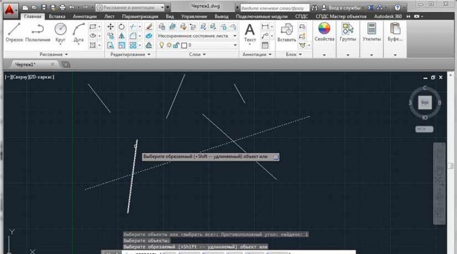
First of all, the program will require you to select objects. Important ! First of all, we choose not those objects that we will shorten or lengthen, but the one with respect to which we will perform trimming.
After selecting the base object, press RMB and specify those segments that we want to trim or lengthen. Important ! If we perform trimming of objects, then we need to point to that part of the segment or arc that we want to remove.
Pay attention to the hint in the command line or dynamic input: when you press the Shift key and select any object, we will lengthen it if we originally selected the “crop” command and vice versa.

See many others free videos AutoCAD for beginners
Other related lessons
Did you know that in AutoCAD it is absolutely illiterate to scale drawings immediately on a large canvas, that is, in the “Model” space? Yes, this is a truth that few people know about. Sad but true. But you have the opportunity to unravel this secret, hidden from us, of how to quickly set and painlessly change the scale of views on sheets in AutoCAD. […]
You can calculate the area in the AutoCAD program different ways. The value of the surface area is used in various calculations: payload or snow load, the amount of finishing work, or simply, an indication of the area of \u200b\u200bthe room on the plan. The two most common ways to measure area are shown in the video below. From it you will learn how easy it is to calculate the area in AutoCAD. Learn to work quickly in […]
In this article and video tutorial, we will learn how to create tables in AutoCAD. The Table command is on the ribbon. Find it and click to insert the table. A dialog box appears in which you can set the size of the future table by adjusting the number of its columns and rows, as well as their width and height. After setting the parameters and clicking OK, […]
The last step in the construction of the drawing is the final design of the contour of the technological groove. Of course, this problem could be solved by applying the tool four times Pairing(using tool Similarity to create the top horizontal groove contour line). However, we will look at another tool that will allow us to solve this problem a little faster. This tool is called crop and it is intended for trimming lines that protrude beyond the limits of other lines or drawing objects. As with the tool lengthen, cropping is performed in two steps. At the first stage, auxiliary lines are selected, since the lines are trimmed before they intersect with them.
1. Run the tool crop by clicking on the button crop panels Change or by selecting the command from the menu Edit » Crop or by typing in the command window the command crop or simply arr. As with the command lengthen, AutoCAD in the command window prompts you to select objects that will be used as secant edges in this case.
2. Select the two vertical lines created with the tool Similarity, which indicate the right and left vertical boundaries of the technological slot contour (Fig. 2.20) and press Enter to complete the selection.
Rice. 2.20 Lines selected as secant edges
3. Select a horizontal line indicating the bottom line of the contour to the left or right of them (Fig. 2.21).
4. Repeat the operation described in step 3, but this time select the remaining segment of the bottom line that extends beyond the other secant edge.

Rice. 2.21 Selecting the right segment of the bottom line of the groove for trimming
5. Press Enter to end the command crop. All that remains for us is to create the top line of the technological groove contour, and then cut off the upper parts of the lines that we just used as secant edges.
Note. Cancel a failed command crop can be done by typing in the command window Cancel or simply O or by clicking the button Cancel toolbar standard.
6. Using the tool Similarity shift the bottom line of the groove contour up by 30 units.
7. Run the tool again crop and select the newly created upper horizontal line of the groove contour as the secant edge (Fig. 2.22).

Rice. 2.22 The upper horizontal line of the contour of the groove is selected as a secant edge
8. After pressing Enter to complete the selection of cutting edges, when prompted by AutoCAD, select the lines to be cut, first the left and then the right vertical lines, as shown in fig. 2.23. AutoCAD will immediately cut the selected lines.

Rice. 2.23 Left vertical line circumcised, now it's the turn of the right
9. Press Enter to complete the command crop. Comparing the result obtained (Fig. 2.24) with the original drawing (see Fig. 2.2), we see that the goal has been achieved. A few of the simple tools learned in this chapter will come in handy not only in the rest of the chapters in this book, but also in your daily work with AutoCAD.

Rice. 2.24 Final view of the drawing
If you feel that you are not quite confident with the instruments With lines, Similarity, Erase, Pairing, crop And lengthen, you can try to repeat the creation of the considered drawing a few more times. In AutoCAD, there are no right and wrong methods for obtaining the result - you can use a different sequence for creating a drawing or a different sequence for using tools that is different from the one suggested by the author. Alternatively, you can try to execute the drawing by launching all the tools by entering their aliases in the command window.
With practice, you can close AutoCAD without saving the completed drawing. To do this, select the command from the menu File » Exit or just press Alt+F4. (If you don't want to exit AutoCAD, just close the current drawing by selecting the menu command File » Close or by pressing Ctrl+F4.) When prompted by AutoCAD to save the drawing, click the No.
Now you are ready to study the material of the next chapter, in which we will talk about the next problem. The object shown in the drawing we just created is 470 by 400 units. In this case, it can be assumed that we are talking about millimeters. However, such an assumption can not always be made. For example, if we have a drawing of a power generator shaft with a length of 10 units, then what length does this part actually have: 10 mm, 10 cm or 10 m? In addition, the drawing of the office pedestal corresponds to the default dimensions of the AutoCAD window, so we had no problems in this sense either. But imagine that you really need to create a drawing of a 15-meter shaft of an electric generator with a diameter of several meters! Finally, if you are creating a drawing for foreign partners who operate not in metric, but in the imperial system of units, you willy-nilly have to create a drawing not in meters and centimeters, but in feet and inches. Therefore, in the next chapter, we will talk about how to set the drawing parameters in accordance with the task facing the AutoCAD user.
If you had the task of cutting a part of a block or array, cutting a block or array according to a certain office, then you probably already noticed that the command Trim (_TRIM) is useless in this case.
At least until the block or array is blown up. How to cope with this task without splitting blocks and without splitting arrays will be discussed in this article.
Looking ahead, I will say that a team will come to our aid Clip (_CLIP). And to make it more interesting to read, I will not only describe the procedure for working with the team, but also show concrete examples its application.
Example #1. Block pruning
There is a block of a truck with cargo, which partially drove into the hangar. It is required to hide the part of the block that is inside the hangar. Blowing up a block and manually cutting off everything inside the building is a rather painstaking task, and it will be very inconvenient to work with such an object later.
Select a block. Go to tab "Insert" tapes, panel "Link" and choose a team Clip (_CLIP)

The command line will prompt:
Please note that the option <Новый> is selected as the default (triangular brackets indicate this), it suits us, so we just press SPACE or ENTER.
Next, we will be asked what exactly we want to use as a clipping path - an existing polyline, polygonal or rectangular area. We have the option Rectangular- note that it is offered as a default, so we just press again SPACE or ENTER.
Then we need to specify the first corner of the block area that we want to keep, and then the second corner - this is done two consecutive clicks of the left mouse button (LMB):

This is the result we get:

The clipping was successful, but we see a clipping path, which we do not need in this case. To control clipping paths, you need to select one of three options for displaying paths in the ribbon:

Let's choose an item Hide Outlines. Now the result really suits us:

I draw your attention to the fact that when a block is selected, the contours will be highlighted, and moreover, they are interactive - i.e. you can change them by moving the corresponding markers and the cropping result will change, which is quite convenient:

Example #2. Trimming an array with tiles along the contour of the room
IN this example we will consider a very useful case for those who are engaged in interior design, and in particular, the layout of tiles in AutoCAD. The description will be less detailed, because. We have already covered the basics in the first example, but here I will focus only on those steps that will differ.
So, we have a bathroom wall, the tiles in which are laid out using a Rectangular Array:

As you can see, the array goes beyond the wall, and moreover, you need to make a slot under the door. We do not want to blow up the array and cut it off, and this will not work, because the pattern uses hatching.
The beginning will be as in example No. 1 - select the array, call the command Undercut, press SPACE or ENTER to create New outline pruning. But this time we choose the option Polygonal:
Now we need with a few clicks sequentially indicate all the points of our contour and after specifying the last point press SPACE or ENTER:

In total, 8 points were obtained, and the cropping result is presented below:

Agree, very simple and convenient.
Example #3. Creating your own hatching (texture) from a block
We have this detail:

The item is made of timber and this species- this is the end of this very beam. We want to apply a texture to the end, which would resemble the growth rings of a tree and would simplify the visual perception of the part. To do this, create a block of concentric circles, something like this.
Frankly speaking, such operations are best performed following Woland's "golden" rule - "treat like with like." It is better to crop a bitmap image in a program that is specifically designed to work with such objects, in the same Photoshop. How to do it in Word, squeezing in the browser or cropping bitmap in AutoCAD.
After all, the idea is very simple - why insert an image on a Web page with a size of 1,000 by 800 and a volume of 20 MB, then to compress it to 150 by 100, the volume will remain at 20 - and the traffic during the download, and the space on the server's hard drive, Let's take into account that there can be up to hundreds of such pictures. Create this version in Photoshop with the desired size, and it will only weigh 100 kb. So, it's one thing to download 20 MB, and quite another thing to download 100 kb, 200 times less!
Approximately the same can be said about AutoCAD, which, with a complex drawing, creates quite voluminous files - let's not forget about 3D, shading and light sources. In general, it doesn’t hurt to always help yourself, and you can be sure that the program will help you.
However, there are different situations. In the end, there is no suitable tool at hand, and there is no time for this work. Then AutoCAD can help solve this problem - how to crop a picture, behind which the drawing is invisible.
A few fairly simple operations, almost following the example of Word
The order of work is quite simple and differs little from working in the same text process from Microsoft - Word.
We act as follows:

Advanced cropping options
But the user has more than just a simple rectangular clipping path. The outline can be anything. Moreover, you can even make an inversion - what gets inside the contour will become invisible.
To create a "broken" path:
- After selecting the command for creating a contour, select the "Polygonal" mode.
- Following the image, we create a polygon according to the usual rules of AutoCAD.
- As the polygon is closed, cropping will occur.

It is possible that the set snapping mode will interfere with the creation of the polygon. In this situation, the mode can be temporarily disabled in the status bar.
Crop cancellation (as the above operations are also called) is performed by selecting the "Delete cropping" command for the selected image on the "Cropping" panel.
Command line option
The clipping operation on the command line corresponds to the "_imageclip" command. It is called on some versions of the program through the menu "Modify" / "Clip" / "Image" ("Transformations" / "Cropping" / "Image"). Here is the order of using the command:
- First, a request to select a picture appears, if this was not done beforehand, before running the "Select image to clip:" command.
- Then the general prompt appears "Enter image clipping option
:" - creating a new outline (New - default), deleting it and restoring the full view of the picture (Delete), temporarily disabling cropping (OFF - it remains, just not temporarily applied yet), turning cropping back on (ON). - If the clipping construction mode is selected, then a request for its form “Enter clipping type
:". By default, it is proposed to use cropping by a rectangle - Rectangular, but you can also choose a polygon - Polygonal. - When choosing a rectangle, you will need to specify its upper left - lower right corners, and when choosing a polygon - specify the corners, the polygon is initially accepted as closed, therefore, according to the rules of AutoCAD, the user does not require closure - we complete the construction by simply pressing Enter.
When building, very often fragments of segments, arcs, etc. are found that "crawled out" beyond the boundaries of objects, the question arises of how to cut lines in AutoCAD. To crop such fragments in AutoCAD, use the "Crop" command. Lines, rectangles, splines, rays, etc. can also be used as clipping elements.
Cropping in AutoCAD is carried out by specifying the so-called cutting edge and a fragment of the object, which, after crossing with this edge, must be removed.
The crop command in AutoCAD, like other Editing commands in AutoCAD, is very popular and easy to use if you study it in more detail. You can call the "Crop in AutoCAD" command, as always, in several ways:
1. On tab "Home" → Edit panel.
2. By entering a keyword "OBR" and then pressing "Enter".

So all the same, how to crop in AutoCAD? To answer this question, it is necessary to consider the components of cropping: how to crop lines in AutoCAD, how to crop an image in AutoCAD and how to crop an object in AutoCAD, and learn general lessons or the basics of how to work with AutoCAD. First you need to select the cutting edge (or edges), and then you have to select the objects to be trimmed.
Let's give an example of how to crop an object in AutoCAD: let's say you need to crop a part of a segment that has gone beyond the rectangle. In this case, the cutting edge will be the rectangle itself, and the cut object will be the part of the segment outside the rectangle. I have shown the whole process in the picture.


There can be many cutting edges, as well as cut objects. For example, I sometimes select all objects or most of them as cutting edges. And then I click LMB on those elements that I want to crop. Immediately after specifying the object, it is trimmed. Trimming can be ended by pressing the "Enter" or "Esc" key. Parts of the cutting edges themselves can also be cut objects.


By the way, if, when selecting cropped objects, the selection is made with the “Shift” key pressed, then the objects will not be cropped, but lengthened.
When selecting cropping objects, you can use the following options:
✗ Line and Sekramka– allow you to select cropping objects using a temporary polyline and a crossing box.


✗ Edge– enables/disables the edge continuation mode up to an imaginary intersection.
When enabled, cropping in AutoCAD will also be performed in cases where the cropped object does not clearly intersect with the cutting edge. Whether this mode is enabled or not can be seen from the command line prompt when calling the “Crop” command in AutoCAD.
If it says “Edges = No Continuation”, it means that the mode is off. You can turn it on before selecting the cropping objects by typing command line(or just from the keyboard) the letter "C".
✗ Cancel- an option that allows you to cancel the trimming of the last object without completely canceling the execution of the entire command.