Windows 7 page error memory. Device Manager error codes
Read also
Preemptive/non-preemptive algorithms.
In the case of a preemptive algorithm operating system at any time can interrupt the execution of the current thread and switch the processor to another thread. In non-preemptive algorithms, the thread that is given the processor only decides when to transfer control to the operating system.
Algorithms with quantization.
Each thread is given a time slice during which the thread can execute on the processor. When the quantum expires, the operating system switches the processor to the next thread in the queue. Quantum is usually equal to an integer number of system timer intervals 1.
Algorithms with priorities.
Each thread is assigned a priority - an integer indicating the degree of privilege of the thread. The operating system, if there are several threads ready to run, selects the thread with the highest priority.
Windows implements a mixed scheduling algorithm - preemptive, based on quantization and priorities.
- Multitasking type for DOS application
- Service guarantees
- Scheduling foreground processes
- Purpose of the paging file
- Processes P1, P2, P3 allocate 100, 20, 80 MB of memory. The system has 128MB of RAM. What is the size used memory in the swap file. What is the size of the swap file.
- What is a "page fault"?
Interrupt 14 -Page fault (#PF): Intel386…
Generated if the page engine is activated (CR0.PG = 1) and one of the following situations occurs when translating a linear address to a physical one:
- element of the page table or page directory used in address translation, has zero presence bit, i.e. the required page table or the page is not present in physical memory;
- the procedure does not have privilege level, sufficient to access the selected page, or attempts to write to a page that is write-protected for the current privilege level.
The page fault handler obtains information about its cause from two sources: the error code, which is pushed onto the stack, and the contents of the CR2 register, which contains the linear address that caused the error. The page fault code has a special format (Fig. 3.7.).
An interrupted program, after eliminating the reasons that caused the page fault (for example, loading a page into physical memory), can be continued without any additional adjustments.
If a page fault was caused due to a violation of page security privileges, the access bit (A) in the corresponding page directory entry is set. The behavior of the access bit in the corresponding element of the page tables for this case is not regulated in Intel processors and may be different in different models.
- A high page error rate indicates:
Program insecurities
RAM unreliability
Other: explain
Column “Errors of page missing from memory/sec.”
In the column “Errors of page out of memory/sec.” (Hard Faults/sec) shows the average number of page out of memory errors per second over the last minute. If a process tries to use more physical memory than is available in this moment time, the system writes part of the data from memory to disk - to the paging file. Subsequent access to data saved to disk is called a page out of memory error.
What do page out of memory errors mean?
Now that you have an idea of what information is collected in the Processes table, let's see how you can use it to monitor memory allocation. When running applications and working with files, the memory manager monitors the working set size of each process and records requests for additional memory resources. As a process's working set increases, the dispatcher matches these requests to the needs of the kernel and other processes. If the available address space is insufficient, the dispatcher reduces the working set size by storing data from memory to disk.
Later, when reading this data from disk, a page out of memory error occurs. This is quite normal, but if errors occur simultaneously for different processes, the system requires additional time to read data from the disk. Too much common mistakes absence of a page in memory, respectively, reduces system performance. You've probably experienced unexpected slowdowns in all applications, which then also suddenly stopped. This slowdown was almost certainly due to active data redistribution between physical memory and swap.
The conclusion follows: if page out of memory errors for a particular process occur too often and regularly, The computer does not have enough physical memory.
To make it more convenient to monitor processes that cause frequent page out of memory errors, you can mark them with flags. In this case, the selected processes will move to the top of the list, and in the graph of page missing errors they will be represented by an orange curve.
It's worth considering that memory allocation depends on a number of other factors, and monitoring for page-out-of-memory errors is neither best nor the only way identifying problems. However, it can serve as a good starting point for observation.
- How is thread priority determined in Windows?
Priorities
The Windows OS implements preemptive priority scheduling, when each thread is assigned a certain numerical value - a priority, in accordance with which the processor is allocated to it. Threads with the same priorities are scheduled according to the Round Robin algorithm (carousel). An important advantage of the system is the ability to preempt threads running in kernel mode - the executive system code is completely reentrant. Only threads holding a spinlock are not preempted (see "Synchronizing Threads"). Therefore, spinlocks are used with great care and are set for a minimum amount of time.
The system provides 32 priority levels. Sixteen priority values (16-31) correspond to the real-time priority group, fifteen values (1-15) are for normal threads, and a value of 0 is reserved for the system page zeroing thread (see Figure 6.2).
Rice. 6.2. Thread Priorities
To relieve the user of the need to remember numerical values of priorities and be able to modify the scheduler, the developers introduced into the system priority abstraction layer. For example, the priority class for all threads of a particular process can be set using a set of constant parameters of the SetPriorityClass function, which can have the following values:
- real time (REALTIME_PRIORITY_CLASS) - 24
- high (HIGH_PRIORITY_CLASS) - 13
- above normal (ABOVE_NORMAL_PRIORITY_CLASS) 10
- normal (NORMAL_PRIORITY_CLASS) - 8
- below normal (BELOW_NORMAL_PRIORITY_CLASS) - 6
- and idle (IDLE_PRIORITY_CLASS) 4
The relative priority of a thread is set by similar parameters of the SetThreadPriority function:
A set of six process priority classes and seven thread priority classes forms 42 possible combinations and allows us to form the so-called basic thread priority
The default base priority of a process and primary thread is the value in the middle of the process priority ranges ( 24, 13, 10, 8, 6 or 4). Changing the priority of a process entails changing the priorities of all its threads, while their relative priorities remain unchanged.
Priorities 16 through 31 are not really real-time priorities because Windows' soft real-time support makes no guarantees about thread timing. These are simply higher priorities that are reserved for system threads and those threads that are given such priority by a user with administrative rights. However, the presence of real-time priorities, as well as preemptibility of kernel code, localization of memory pages (see "Operation of the memory manager") and a number of additional features- all this allows you to perform it in the OS environment Windows applications soft real time, for example, multimedia. The system thread with zero priority is busy clearing memory pages. Regular user threads can have priorities from 1 to 15.
Related information.
In my last article "" I talked about the capabilities of the Windows 7 Resource Monitor (Resource Monitor), explained how to use it to monitor the distribution of system resources between processes and services, and also mentioned that it can be used to solve specific problems - for example, to analyze memory consumption. This is exactly what this article will discuss.
A little about memory
Before starting the analysis, I’ll briefly talk about how memory is controlled. This will make it easier for you to understand what information is presented in the Windows 7 Resource Monitor.
Windows 7 Memory Manager creates virtual system memory, which consists of available physical RAM and the paging file on the hard drive. This allows the operating system to allocate fixed-length blocks of memory (pages) with sequential addresses in the physical and virtual memory.
Launching Windows 7 Resource Monitor
To launch Windows 7 Resource Monitor, open the Start menu, type "Resmon.exe" in the search bar and click . In the window that opens, select the “Memory” tab (Fig. A).
Figure A: The Memory tab in Windows 7 Resource Monitor provides detailed memory allocation information.
Processes table
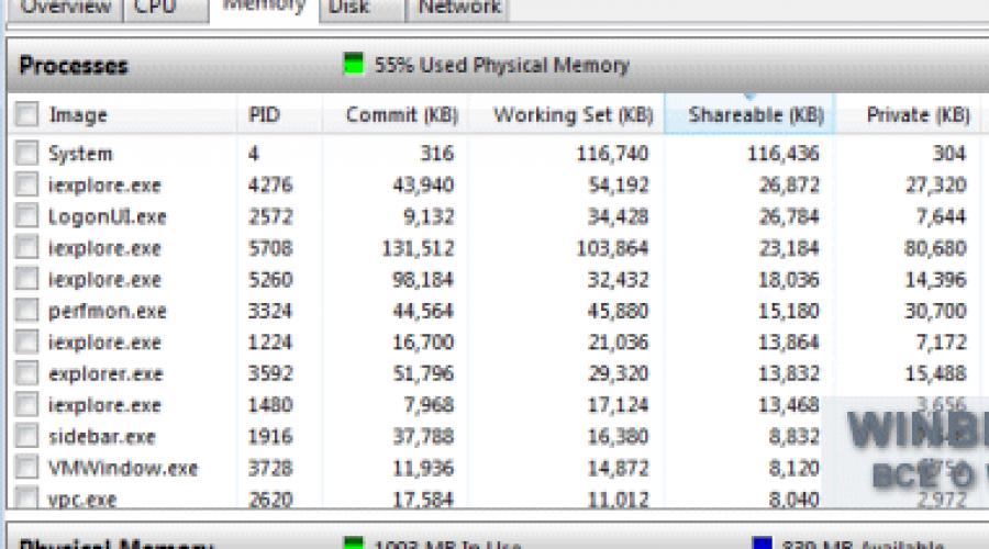
The Memory tab has a Processes table (Figure B) that lists all running processes and breaks memory usage into several categories.

Figure B: Memory usage information for each process is broken down into several categories.
Column "Image"
The “Image” column indicates the name of the process executable file. Processes, launched by applications, it is very easy to find out - for example, the process “notepad.exe” clearly belongs to Notepad. Processes named "svchost.exe" represent various operating system services. The service name appears in parentheses next to the process name.
Process ID column
The Process ID (PID) column indicates the process number - a unique combination of numbers that allows you to identify the running process.
"Completed" column
The Commit column indicates the amount of virtual memory, in kilobytes, that the system has reserved for this process. This includes both the physical memory used and the pages stored in the paging file.
Column "Working set"
The Working Set column indicates the amount of physical memory in kilobytes used by the process at a given time. The working set consists of public and private memory.
Column "General"
The “Shareable” column indicates the amount of physical memory in kilobytes that this process shares with others. Sharing a single memory segment or swap page for related processes can save memory space. This physically stores only one copy of the page, which is then mapped to the virtual address space of other processes that access it. For example, all processes initiated by system DLLs- Ntdll, Kernel32, Gdi32 and User32 - use shared memory.
Column "Private"
The Private column indicates the amount of physical memory, in kilobytes, used exclusively by this process. It is this value that allows you to determine how much memory a particular application needs to operate.
Column “Errors of page missing from memory/sec.”
In the column “Errors of page out of memory/sec.” (Hard Faults/sec) shows the average number of page out of memory errors per second over the last minute. If a process tries to use more physical memory than is currently available, the system writes some of the data from memory to disk - to the page file. Subsequent access to data saved to disk is called a page out of memory error.
What do page out of memory errors mean?
Now that you have an idea of what information is collected in the Processes table, let's see how you can use it to monitor memory allocation. When running applications and working with files, the memory manager monitors the working set size of each process and records requests for additional memory resources. As a process's working set increases, the dispatcher matches these requests to the needs of the kernel and other processes. If the available address space is insufficient, the dispatcher reduces the working set size by storing data from memory to disk.
Later, when reading this data from disk, a page out of memory error occurs. This is quite normal, but if errors occur simultaneously for different processes, the system requires additional time to read data from the disk. Too frequent page-out-of-memory errors consequently reduce system performance. You've probably experienced unexpected slowdowns in all applications, which then also suddenly stopped. This slowdown was almost certainly due to active data redistribution between physical memory and swap.
The conclusion follows: if page out of memory errors for a particular process occur too often and regularly, the computer does not have enough physical memory.
To make it more convenient to monitor processes that cause frequent page out of memory errors, you can mark them with flags. In this case, the selected processes will move to the top of the list, and in the graph of page missing errors they will be represented by an orange curve.
It's worth keeping in mind that memory allocation depends on a number of other factors, and monitoring page-out-of-memory errors is not the best or only way to identify problems. However, it can serve as a good starting point for observation.
Table "Physical Memory"
The Processes table provides detailed information about memory allocation between separate processes, and the Physical Memory table gives an overall picture of RAM usage. Its key component is the unique histogram shown in Fig. C.

Figure C: The histogram in the Physical Memory table provides an overview of memory distribution in Windows 7.
Each section of the histogram is indicated by its own color and represents a specific group of memory pages. As the system is used, the memory manager moves data between these groups in the background, maintaining a delicate balance between physical and virtual memory to ensure efficient work all applications. Let's take a closer look at the histogram.
Section “Reserved equipment”
On the left is the “Hardware Reserved” section, labeled gray: This is the memory allocated to the needs of the connected hardware, which it uses to interact with the operating system. Memory reserved for the hardware is locked and cannot be accessed by the memory manager.
Typically, the amount of memory allocated to the equipment ranges from 10 to 70 MB, but this figure depends on the specific system configuration and in some cases can reach several hundred megabytes. Components that affect the amount of reserved memory include:
;
Components motherboard- for example, advanced programmable input/output interrupt controller (APIC);
sound cards and other devices that perform memory-mapped input/output;
PCI Express (PCIe) bus;
video cards;
various sets microcircuits;
flash drives.
Some users complain that their systems reserve an abnormal amount of memory for their hardware. I have never encountered such a situation and therefore I cannot vouch for the effectiveness of the proposed solution, but many note that the update BIOS version allows you to solve the problem.
“In Use” section
The In Use section, shown in green, represents the amount of memory used by the system, drivers, and running processes. The amount of memory used is calculated as the “Total” value minus the sum of the “Modified”, “Standby” and “Free” indicators. In turn, the “Total” value is the “Installed RAM” indicator minus the “Reserved Equipment” indicator.
Section "Changed"
The “Modified” section is highlighted in orange, which represents memory that has been modified but not used. In fact, it is not used, but can be used at any time if needed again. If memory has not been used for a long time, the data is transferred to the page file and the memory goes into the "Waiting" category.
Section "Waiting"
The Pending section, shown in blue, represents memory pages that have been removed from working sets but are still associated with them. In other words, the "Waiting" category is actually a cache. Memory pages in this category are assigned a priority from 0 to 7 (maximum). Pages associated with high-priority processes are given maximum priority. For example, shared processes have high priority, so the pages associated with them are given the highest priority in the Pending category.
If a process requires data from a waiting page, the memory manager immediately returns that page to the working set. However, all pages in the Pending category are available for recording data from other processes. When a process requires additional memory and there is not enough free memory, the memory manager selects the waiting page with the lowest priority, initializes it, and allocates it to the requesting process.
Section "Free"
In the "Free" category, designated blue, represents pages of memory that have not yet been allocated to any process or that have been freed after the process terminates. This section displays both not yet used and already freed memory, but in fact, not yet used memory belongs to a different category - “ Zero pages"(Zero Page), which is so called because these pages are initialized with a zero value and are ready for use.
About the problem of free memory
Now that you have a basic understanding of how the memory manager works, let's take a moment to address a common misconception about the memory management system in Windows 7. As you can see in Figure 1. C, The free memory section is one of the smallest in the histogram. However, it is a mistake to assume on this basis that Windows 7 consumes too much memory and that the system cannot work properly if there is so little free memory.
In fact, it's quite the opposite. In the context of Windows 7's approach to memory management, free memory is useless. The more memory used, the better. By maximizing memory and constantly moving pages from one category to another using a priority system, Windows 7 improves efficiency and prevents data from ending up in the page file, preventing out-of-page errors from slowing down performance.
Memory monitoring
Would you like to observe the control system? Windows memory 7 in action? Restart your computer and immediately after startup, open the Windows 7 Resource Monitor. Go to the Memory tab and pay attention to the ratio of sections in the physical memory histogram.
Then start launching applications. As you run, watch the histogram change. Once you've launched as many applications as possible, start closing them one at a time and watch how the ratio of sections in the physical memory histogram changes.
By doing this extreme experiment, you'll understand how Windows 7 manages memory on your particular computer, and you'll be able to use Windows 7 Resource Monitor to monitor memory allocation under normal day-to-day operating conditions.
What do you think?
Do you like the idea of using Windows 7 Resource Monitor to monitor memory allocation? Share your opinion in the comments!
Many computing systems include one or another version of a memory manager (another name is a memory management unit - MMU), with the help of which a multitasking operating system allocates memory to each task and provides protection from user programs. For example, a typical problem occurs when an application program makes an error when calculating an address, perhaps using an index value that is too large or too small. If the system is not protected, this kind of error can lead to changes in the codes included in the operating system programs or modification of device tables and even cause an unplanned startup of the device with fatal consequences, such as unauthorized writes to the data file.
In addition to protecting the operating system from unintentional destruction, the memory manager provides automatic program relocation. With the help of a memory manager, logical or software addresses of user programs are converted into physical or hardware addresses. These addresses may be located in memory completely different from where the logical addresses point. Address translation causes the operating system and protected I/O devices to be completely removed from the user's address space. Any attempt to read or write memory outside the address space allocated to the user causes the processor to crash the user program.
Information is usually transmitted in chunks consisting of a fixed number of bits; The 80386 MP uses 32-bit chunks unless it is instructed to reduce the chunk size to 16-bits. These portions are named after words. The process of writing a word into a memory system is called recording in memory the process of retrieving a word from memory - reading from memory.
There are two methods of accessing memory: random and sequential. Sequential access is used in those storage systems where words are accessed in some predetermined order. Random access, on the other hand, involves the ability to access the words of a storage system in any order and in approximately the same time.
No matter how perfect the memory is, when a signal passes between devices, delays arise in its propagation. Propagation delay is defined as the time required for a logical signal to travel through a device or sequence of devices forming a logical chain. This delay also takes into account the passage of the signal along all connecting lines between the chips.
Direct Memory Access (DAM)
Direct Memory Access allows external devices and memory to directly exchange data without program intervention. DDP provides maximum I/O speed and maximum process parallelism. While interrupt-driven I/O and software-controlled I/O transfer data through the processor, DMA transfers data directly between the I/O device and memory.
To minimize the number of data buses, special measures are taken to allow the use of a conventional backbone for the DMA. These measures consist in the fact that the processor releases the highway, and the external device captures it and uses it to transmit data.
During the DAP, program execution is usually suspended. The trunk is released as soon as the DMA request control line is excited. The processor terminates the current operation, frees the address and data lines, and asserts a signal on one of the control lines to prevent unintentional decoding of undefined control signals.
The I/O interface transfers data directly to memory using a special register. When there is a need to transfer data, the interface requests a memory cycle from the processor. Once acknowledged, the interface transfers the data directly to memory while the processor pauses for one memory cycle. The logic that performs this transfer is called channel.
The channel contains a register to store the address of the memory cell to or from which data is being transferred. In most cases, the channel also includes a word counter to count the number of direct transfers performed. In addition, the channel must contain circuitry that ensures the exchange of control signals, synchronization and other auxiliary operations. In Fig. Figure 13.4 shows the logical connections between the CPU and the DMA controller.
RAP components. The main components of a DMA are a request trigger, an address register, a counter, and a data register, which is used by the peripheral device. Sending data over a DMA channel involves several stages: 1) initializing the DMA logic to perform DMA during repeated cycles of bus seizing; 2) activation of the PDP asynchronous with respect to program operations; 3) notification of the end of transfers (by a signal from the meter or as a result of a change in the state of the device); 4) calling the “cleaning” program at the end of transfers; 5) completion of the DDP using an interrupt service program, which returns control to the main program.
Block data forwarding. The DDP procedure for high-speed devices uses block transfer of data. While executing the current program, the processor initiates the transfer of a block of data and determines the number of words that make up the block. However, the actual transmission of words is performed under the control of a separate device - the DMA controller. Maximum speed block transmission over the DMA channel is limited only by the duration of the memory cycle (reading or writing) and the operating speed of the DMA controller.
DDP with memory cycle occupation. The program initiates block transfer by placing the start address in the address counter and the number of words in the word counter. and issuing the run command. This type of DDP is often called a DDP with occupying the memory cycle, because it pauses program execution for approximately one machine cycle each time.
When using memory cycle-occupied DMA, data transfer occurs in parallel with other processes running on the CPU. The sequence of actions here is the same as for block transfer, with the exception that the DMA controller takes up memory cycles from the processor and, therefore, slows down its operation (block data transfer over the DMA channel also takes memory cycles, unless DMA is used on a separate bus).
You have connected a new device, but it is slow to work, or the old device has stopped functioning, or is not working correctly. What to do in these cases? Reinstall everything? It’s troublesome, and it’s not always necessary. How to find out what the reason is and how to eliminate it? Very simple. The fact is that in the Windows family of operating systems, and not only, there is a certainDevice Manager, in fact, a very necessary and useful manager, if you can call him that. Here he is, he will help us find out what is the cause of the problem, and my cheat sheet will help us fix the problem. So, in the above mentionedDevice Manager traces of errors in the operation of devices remain in the form of codes. Knowing the error code, it is not difficult to determine the cause of the problem. For the uninitiated, codes are just incomprehensible and meaningless numbers. But to a knowledgeable user, they can tell a lot. I will try, to the best of my ability, to shed light on this topic.
To view device errors, we first need to enter the Device Manager itself. This is how it is done. Sign inControl Panel from the menuStart ( Can,My computer , right key -Properties — Device Manager, or you can do it by specifying a command inexecute , but why complicate everything). If we enter throughPanel management , then the path is:System - Equipment - Device Manager . Select by entering the menudevice Manager , the type of device we are interested in (keyboard, printer, modem, etc.), double-click on it, as a result we will see the devices included in this type. Select the device we need and double-click on it. Look at the column on the About tabgeneral, Device status. If there is a problem with the operation of the device, it will be displayed here as an error code. So we see numbers and numbers. What do they mean? Below I give full list errors, with brief description errors and possible ways elimination. The error code is highlighted in red, its description in blue and the solution in black.
Code 1There is a problem setting up the device, no correct settings or the driver is missing. Click the button Update driver , to launch the wizardHardware update . If there is no driver at all, install it.
Code 3The device driver is damaged, or there is not enough RAM for the device to function correctly.1. Let's remove the damaged driver and install a new one. To do this: Properties - Driver - Delete, then follow the instructions of the wizard. Reboot. Let's open againdevice Manager — Action — Update hardware configuration and follow the instructions of the master. 2. If the problem is a lack of virtual memory, close running applications to relieve memory. To check the memory state we need to go toTask Manager , to do this, press the keyboard shortcutCtrl+Shift+Esc.We can view the virtual memory settings by right-clickingMy computer — Properties - Advanced - Performance - Settings (Options) . You can try to increase the swap file (I described how this is done in one of my previous blog articles), but this is far from a radical measure. You'll have to increase RAM. How this is done is a separate topic beyond the scope of this post.
Code 10In the registry section there is a parameter corresponding to the deviceFailReasonString,the value of this parameter is displayed in the error data, that is, if there is no parameter as such, then an error code appears, in other words, the device cannot be started. Update the driver as above. Or install a newer one.
Code 12There is no supply of resources required for this device. Disable other working devices, at least one, to do this, use the troubleshooting wizard, which, if you follow its instructions, will disable the conflicting device. (Let me briefly remind you: Properties - General - Troubleshooting.)
Code 14Requires a PC restart for this device to work.
Code 16It is impossible to identify the resources that are necessary for the device to operate; the device is not fully configured. You need to assign additional resources to the device. But this can be done without problems if the device belongs toPlug and Play.
Properties - Resources. If there is a resource with the sign ? in the list of resources, select it to assign to the selected device. If the resource cannot be changed, clickChange settings , if this function is not available, uncheckAutomatic setup
Code 18Reinstall the device driver. We try to update the driver or remove it and do it as in the example withcode 3.
Code 19There is insufficient information in the registry about device settings, or the settings are corrupted. RunTroubleshooting Wizard and follow his instructions, if it doesn’t help, reinstall the device as mentioned above. (code 3). Or, if that doesn't help, downloadLast Known Good Configuration. If this does not help, you need the help of a specialist, just as you need to edit the system registry. Without knowledge and experience, there is nothing for you to do on your own; any system administrator will confirm this to you. He who is knowledgeable and able, knows how to do it himself, without me. And for an inexperienced person, it’s better not to try. The registry is the heart of the operating system and only an experienced specialist, or under his supervision, should perform operations on it. I don’t want to offend anyone in any way, but if you haven’t worked with the system registry and if you value your computer, my advice is to forget the way there. I’m not writing for professionals, they don’t need it, but for the average user. Of course, I can write how and what to do there, but this will be a manual explanation and if you damage your computer as a result of the slightest mistake, I will be to blame. I don’t need this at all, and neither do you.
Code 21 The device is being removed from the system, that is, the operating system is trying to remove the device, but the process has not yet completed.
Pause for a few seconds and press the key
Code 22 The device is disabled. The device must be turned on.Action - Enable and follow further instructions.
Code 24 The device is missing or installed incorrectly, the driver is malfunctioning, the device may have been prepared for removal. Remove the device and install again.
Code 28 No driver. Install the driver. To do this, you need to Update the driver, follow the steps as in the instructions for Code 1.
Code 29Device disabled . You must allow the device to operate in settingsBIOSRead the instructions for using the device.
Code 31The system was unable to load drivers for this device . Update the drivers as described above.
Code 32The driver for this device is disabled in system registry . Uninstall and reinstall the driver (described above)
Code 33The operating system cannot determine the resources for this devices . Set up the device or replace it.
Code 34The operating system cannot detect settings devices . Review the documentation supplied with the equipment and configure the configuration manually on the Resources tab.
Code 35The PC firmware does not have the necessary information for correct device operation . Need to updateBIOS.For instructions on how to do this, contact your supplier, or better yet, use the services of an experienced technician.
Code 36The device requires an interrupt to operate.PCIand the device is configured to interruptISAor vice versa . Settings need to be changedBIOScontact an experienced technician.
Code 37The operating system does not recognize the driver for this device . Reinstall the driver (described above).
Code 38The OS cannot load the driver for the device because, the previous driver version remains in memory . You need to restart your PC. Run the Troubleshooting Wizard if it does not start (Properties - General - Troubleshooting) and follow the wizard's instructions. Afterwards there is a mandatory reboot.
Code 39The OS cannot load the device driver. The driver is damaged or it doesn't exist at all . Reinstall the driver as described above.
Code 40There is no access to the equipment because there is no information in the system registry or the information contains an error . Reinstall the driver.
Code 41Device not detected . Run the Troubleshooting Wizard (described above), if this does not help, update the hardware configuration (see above) or update the driver. If not, install more new version drivers.
Code 42The system already has such a driver. That is, there are two different devices With same name, possibly due to an error . Restart your PC.
Code 43Stopping the device due to problems with its operation . Run the Troubleshooting Wizard and follow its instructions.
Code 44An application or service has stopped your device . Restart your PC.
Code 45Device not connected . Connect your device.
Code 46This error appears when the operating system shuts down. You don’t need to do anything, the next time you start the OS everything will work.
Code 47 The device has been prepared for safe removal, but not yet deleted (for example flash) . Remove the device, then connect again, restart your PC.
Code 48The device, or rather its software, is blocked . Update the driver or install a new one.
Code 49The device cannot be started because it has a large volume of the system registry hive, which exceeds valid parameters registry . Remove devices that are not used from the registry. You can do this: Device Manager - View - Show hidden devices. Here you will see hidden devices that are not connected to your PC. Select the devices you want to remove, click Properties for the device - Driver - Remove, then follow the instructions of the wizard and finally restart the PC.
A guide to removing any viruses from a PC with your own hands. All virus removal methods actually work and are tested in practice, step-by-step instruction with illustrations - simple and accessible even for a schoolchild + video tutorials + ultraiso program to create downloaders + useful links to tools in the fight against viruses. Download archive