The modem can operate at two fixed speeds. Coursework: Signal conversion devices
Read also
So, modems and modulation-demodulation...
The term "modem" is an abbreviation for the well-known computer term modulator-demodulator. A modem is a device that converts digital data from a computer into analog signals that can be transmitted over telephone line. This whole thing is called modulation. The analog signals are then converted back into digital data. This business is called demodulation.
The scheme is very simple. The modem receives digital information in the form of zeros and ones from the computer's central processor. The modem analyzes this information and converts it into analog signals, which are transmitted through the telephone line. Another modem receives these signals, converts them back to digital data, and sends the data back to the remote computer's CPU.
Modulation type (Modulation type), which allows you to select frequency or pulse modulation. Pulse modulation is used throughout Russia.
Analog and digital signals
Telephone communication is carried out through the so-called analog (sound) signals. An analog signal identifies information that is transmitted continuously, while a digital signal identifies only the data that is determined at a particular stage of transmission. The advantage of analog information over digital is the ability to fully represent a continuous flow of information.
On the other hand, digital data is less affected by various kinds of noise and rattles. In computers, data is stored in individual bits, the essence of which is 1 (start) or O (end).
If the whole thing is represented graphically, then analog signals are sine waves, while digital signals are represented as square waves. For example, sound is an analog signal because sound is always changing. Thus, in the process of sending information over the telephone line, the modem receives digital data from the computer and converts it into an analog signal. The second modem, located at the other end of the line, converts these analog signals into the original digital data.
Interfaces
You can use the modem on your computer using one of two interfaces. They are:
MNP-5 RS-232 serial interface.
MNP-5 Four-pin RJ-11 telephone cable.
For example, an external modem is connected to a computer via an RS-232 cable, and to a telephone line via an RJ11 cable.
Data compression
In the process of data transfer, a speed greater than 600 bits per second (bps or bps) is required. This is due to the fact that modems must collect bits of information and transmit them further through a more complex analog signal (a very tricky scheme). The very process of such a transfer allows the transfer of many bits of data at the same time. It is clear that computers are more sensitive to transmitted information and therefore perceive it much faster than a modem. This circumstance generates additional modem time corresponding to those data bits that need to be somehow grouped and applied to them by certain compression algorithms. So there were two so-called compression protocols:
MNP-5 (transmission protocol having a compression ratio of 2:1).
V.42bis (transmission protocol having a compression ratio of 4:1).
The MNP-5 protocol is usually used when transferring certain already compressed files, while the V.42bis protocol is applied even to uncompressed files, since it can speed up the transfer of just such data.
I must say that when transferring files, if the V.42bis protocol is not available at all, then it is best to disable the MNP-5 protocol as well.
Error Correction
Error correction is a method by which modems test transmitted information for the presence of any damage that occurred during transmission. The modem breaks this information into small packets called frames. The transmitting modem appends a so-called checksum to each of these frames. The receive modem checks if the checksum matches the information sent. If not, the frame is retransmitted.
Frame is one of the key terms of data transfer. A frame is a basic block of data with a header, information attached to this header, and data that completes the frame itself. The added information includes frame number, transmission block size data, sync characters, station address, error correction code, variable volume data, and so-called indicators. Start of transmission (start bit) / End of transmission (stop bit). This means that a frame is a packet of information that is transmitted ^ as one.
For example, in Windows 98, in the modem settings, there is an option Stop bits (Stop bits), which allows you to set the number of stop bits. Stop data bits are one of the varieties of so-called boundary service bits. The table bit determines the end of the cycle for asynchronous transmission (the time interval between transmitted characters varies) of data in a short cycle.
MNP2-4 and V.42 protocols
Although error correction can slow down data transmission on noisy lines, this method provides a reliable connection. The MNP2-4 and V.42 protocols are error correction protocols. These protocols define how modems validate data.
Like data compression protocols, error correction protocols must be supported by both transmitting and receiving modems.
Flow Control or Flow Control
During a transmission, one modem can send data much faster than another modem can receive the data. The so-called flow control method allows you to tell the receiving modem the information that this modem should stop receiving data at some point in time. Flow control can be implemented both in software (XON/XOFF - Start signal/Stop signal) and in hardware (RTS/CTS) levels. Flow control at the program level is carried out through the transfer of a certain character. After the signal is received, another character is transmitted.
For example, in Windows 98, in the modem settings, there is an option Data bits (Data bits), which allows you to set the information data bits used by the system for the selected serial port. The standard computer character set consists of 256 elements (8 bits). Therefore, the default option is 8. If your modem does not support pseudo-graphics (only works with 128 characters), indicate this by selecting option 7.
In the same place in Windows 98, in the modem settings, there is an option Use flow control,
which allows you to determine how the data exchange is implemented. Here you can correct possible errors that occur when transferring data from the computer to the modem. Default setting XON/XOFF means that data flow control is carried out by software methods through standard ASCII control characters, which send a command to the modem pause / resume transmission.
Flow control at the software level is only possible if a serial cable is used. Since the flow control at the software level regulates the transmission process by sending some characters, a failure or even termination of the communication session may occur. This is explained by the fact that one or another noise in the line can generate a completely similar signal.
For example, with software-level flow control, binary files cannot be transferred because such files may contain control characters.
Through hardware flow control, RTS/CTS transfers information much faster and more securely than through software flow control.
FIFO buffer and UART chips
A FIFO buffer is somewhat similar to a transshipment base: while data is entering the modem, some of it is sent to the buffer capacity, which gives some gain when switching from one task to another.
For example, Windows 98 only supports the 16550 series Universal Asynchronous Receiver Transmitter (UART) chips and allows you to control the FIFO buffer itself. With a checkbox Use FIFO buffers requres 16550 compatible UART (Use FIFO buffers) you can lock (prevent the system from accumulating data in the buffer capacity) or unlock (allow the system to accumulate data in the buffer capacity) the FIFO buffer. Pushing a button advanced, you turn to the dialogue Advanced Connection Settings, whose options allow you to configure your modem's connection.
S-registers
S-registers are located somewhere inside the modem itself. It is in these same registers that settings are stored that in one way or another can affect the behavior of the modem. There are a lot of registers in the modem, but only the first 12 of them are considered standard registers. S-registers are set in such a way that they send a command to the modem ATSN=xx, where N corresponds to the number of the register to be set, and xx specifies the register itself. For example, through the SO register, you can set the number of rings to answer.
IRQ interrupts
Peripherals communicate with the computer's processor through what are known as IRQs. Interrupts are signals that cause the processor to suspend an operation and transfer its execution to the so-called interrupt handler. When the CPU receives an interrupt, it simply suspends the process and hands over the interrupted task to an intermediary program named Interrupt Handler. The whole thing works regardless of whether an error was detected in the operation of a particular process or not.
Information communication port or simply COM port
The serial port is very easy to find out. You can do this by simply looking at the connector. The COM port uses a 25-pin connector with two rows of pins, one of which is longer than the others. At the same time, almost all serial cables have exactly 25-pin connectors on both sides (in other cases, a special adapter is required).
The COM port (serial port) is the port through which computers communicate with devices such as a modem and mouse. Standard personal computers have four serial ports.
COM 1 and COM 2 ports are normally used by the computer as external ports. By default, all four serial ports have two IRQs:
COM 1 bound to IRQ 4 (3F8-3FF).
COM 2 bound to IRQ 3 (2F8-2FF).
COM 3 is tied to IRQ 4 (3E8-3FF).
COM 4 is tied to IRQ 3 (2E8-2EF).
This is where conflicts can arise, since external ports of other 1/0 I / O devices or controllers can use the same IRQs.
Therefore, after assigning a COM port or IRQ to the modem, you should check other devices to see if they have
the same serial ports and interrupts.
I must say that devices connected to the telephone line in parallel with the modem (especially AON) can significantly degrade * the quality of your modem. Therefore, it is recommended to connect telephones through the jack in the modem designed for this purpose. Only in this case, he will disconnect them from the line during operation.
Your modem's flash memory
Flash memory is read-only memory or PROM (Read Only Memory) that can be erased and reprogrammed.
All modems with the string "V. Everything" in their name are subject to reprogramming. In addition, "Courier V.34 dual standart" modems are subject to software upgrade if the line Options the response to the ATI7 command contains the V.FC protocol. If the modem does not have this protocol, then the upgrade to "Courier V. Everything" is done by replacing the daughter board.
There are two modifications of Courier V. Everything modems - with the so-called supervisor frequency of 20.16 MHz and 25 MHz. Each of them has its own firmware versions, and they are not interchangeable, i.e. firmware from the 20.16 MHz model will not work for the 25 MHz model, and vice versa.
User Programmable NVRAM
All modem settings are reduced to correct installation NVRAM register values. NVRAM is a user-programmable memory that retains data when the power is turned off. NVRAM is used in modems to store the default configuration loaded into RAM at power on. NVRAM programming is done in any terminal program using AT commands. A complete list of commands can be obtained from the modem documentation, or obtained in the terminal program by commands AT$ AT&$ ATS$ AT%$. Write to NVRAM factory settings with hardware data control - AT&F1 command, then make adjustments to the modem settings in conjunction with a specific telephone line and write them to NVRAM by command AT&W. Further initialization of the modem must be done through the command ATZ.4.
Application Software for Data Communication
Data programs allow you to connect to other computers, BBS, Internet, Intranet and other information services. You may have a very extensive set of such programs at your disposal. For example, in Windows 98, you have at your disposal a very good terminal client, Hyper Terminal.
If you are having problems communicating with other modems
First you need to evaluate the nature of the communication line. To do this, after a successful session, before reinitializing the modem, enter the commands ATI6- communication diagnostics, ATI11- connection statistics, ATY16- amplitude-frequency characteristic. The received data must be written to a file. After analyzing the received data, it is necessary to make changes to the current configuration and then write them to NVRAM using the command AT&W5.
Russian telephone lines and imported modems
The choice of modems today is quite large, and the difference in their cost is very significant. Transfer rates of more than 28,800 bps on Russian telephone lines are usually unattainable. Above 16,900 bps can only be obtained if the Internet service provider has lines on the PBX to which your phone is connected. In other cases, working on the Internet is too tedious, because at a typical (and even not always achievable) speed of 9,600 bps, it turns into a continuous wait. Therefore, for stable data transmission with interference in the telephone line, you need a high-end modem that costs at least $400.
Which modem is better - internal or external?
The internal modem is installed in a free expansion slot on the computer motherboard and connected to the built-in power supply, while the external modem is a stand-alone device connected to the computer via a standard serial port.
Each of the designs has its own advantages and disadvantages. The internal modem occupies a system bus slot (and there are usually not enough of them), it is difficult to monitor its operation due to the lack of indicators, besides, the models described are fundamentally unsuitable for notebook-type laptop computers that have a narrow-profile case and in most cases do not with expansion slots. At the same time, the internal modem is several tens of dollars cheaper than external analogues, does not take up space on the table and does not create a mess of wires. Using an external modem means that the computer to which it is connected has the most modern serial port control chips (UART). UART chips appeared in the first PCs, since even then it became clear that data exchange via a serial port is too slow and complicated operation and it is better to entrust it to a special controller. Since then, several UART models have been released. In computers such as the IBM PC and XT, as well as in fully compatible with them, the 8250 chip was used, in AT it was replaced by the UART 16450. turn", and today the UART 16550A becomes the standard - a microcircuit similar to the previous one, but with the defects eliminated. The lack of buffers in all chips, except for the last one, leads to the fact that data transfer through the serial port at speeds above 9600 bps becomes unstable (using MS Windows reduces this threshold to 2400 bps).
If you need to connect a high-speed external modem to a computer using an obsolete UART chip, you must either change the multicard or add a special expansion card (which will occupy one bus slot and deprive the external modem of a major advantage). Internal modems do not have this problem - they do not use the COM port (more precisely, they contain it). Now internal modems have another advantage, also related to speed. According to the V.42bis specification, data can be compressed by about a factor of four in transmission, so a modem operating at 28800 bps must receive data from or send data to the computer at 115600 bps, which is the limit for serial PC port. However, 28800 bps is not the limit for a telephone line, where the maximum lies somewhere around 35000 bps, but on digital lines(ISDN) throughput exceeds 60,000 bps. Therefore, in this situation, the serial port will become the "bottleneck" of the entire system, and the potential capabilities of an external modem will not be realized. Modem manufacturers are now developing models that can connect to a faster parallel port, but it is clear that the devices sold now will not be able to adapt to this.
At the same time, many modems can be upgraded to work at high speeds, up to the ability to work on ISDN. But everything rests on a restrictive barrier on the part of the computer, which for an internal modem is significantly higher than 4 MB / s (the throughput of the ISA bus). By the way, all ISDN modems are internal. True, all this will be tomorrow (and maybe the day after tomorrow), but today one thing can be said: choose a device of the type that you like - there are no functional differences between internal modems and their external counterparts.
Which modem to choose and how to choose it
The modem cannot be unique. Your modem must be understood by other modems. This means that the modem must support the maximum number of standards, that is, error correction, communication methods and data compression. The most common standard is V.32bis for 14000 bps modems. For 28800 bps modems, the standardized protocol is V.34.
In addition, it must be emphasized that modems with a data rate of 16800, 19200, 21600 or 33600 are not standard.
No error correction should be programmatic. Everything must be sewn into the modem by its manufacturer.
About the outside and the inside. An external modem is connected to your serial port via a special cable. Such a modem, as a rule, has a volume control, information indicators, a power supply and other sometimes useful gadgets. If you are a professional, then it should not matter to you which modem you choose - internal or external. Usually, a good internal modem through special software emulates well all the visibility of an external modem.
Do not buy purely imported modems. These pieces of iron do not get along on our ancient lines. Purchase only certified modems, that is, hardware specially stitched for our dirty telephone exchanges.
In Russia, this choice is very small. This market was filled by two companies: ZyXEL from sunny Taiwan and U.S. Robotics from USA. Modems of the last firm are chosen by professionals (Courier), the first - by all the rest, that is, all those users who choose the so-called ultra-reliable ZyCell protocol.
So, choose Courier. And believe me, this is not advertising.
Modem selection.
All you need to know about how a modem works: A modem is a device that allows you to connect computers to each other via telephone network. The possibilities available to you with such a connection are determined solely by the software that you will use, and the quality of the modem itself determines the speed of the connection. All the features of the modem you should know:
All other characteristics of modems are of interest only to specialists.
External modems work, as a rule, better than internal ones, more clearly - the lights on the panel flash, and make a stronger impression on your friends (the larger the modem and the more lights on it, the stronger the impression), but the internal ones take up less space in your room (because they are located entirely inside the computer).
Having bought a modem and connected it to a computer (or put it in a computer), you can call Data Force IP (tel. 755-9363) for a trial and out of curiosity and obtain the necessary data for a trial connection to the Internet.
External modems
To connect an external modem to the computer, it is necessary (and sufficient) that it has a free serial port (COM port) and a cable to connect the modem to this port. Usually there are two serial ports in a computer, a “mouse” will be connected to one of them. Serial port connectors come in 9-pin and 25-pin connectors. Usually a computer has one 9-pin connector (the “mouse” is connected to it) and one 2 5-pin connector (if you don’t have a modem, then this connector usually remains free), both are of the “male” type, that is, with pins. The modem usually has a 25-pin female connector, that is, with holes. In this case, you need a female-to-male cable with 25-pin connectors on both sides. If the computer only has a 9-pin connector available, then you need a cable that has a 9-pin female and a 25-pin male. You can almost certainly purchase the cable at the same place where you purchased the modem.
If you are purchasing a high-speed modem, then the characteristics of your computer's serial port become important to you. You need to have a high speed serial port (eg such magic words are UART16550A). Usually on an external modem there is a row of light bulbs, under each of which two letters are signed. Here are the most common designations:
- HS - high speed
- AA - willingness to answer the call
- CD - carrier frequency detected
- OH - dialing initialization
- RD - data is being received
- SD - data transfer in progress
- TR - ready to work
- MR modem enabled
- RS - request to send data
- CS - readiness for data transfer.
If you have purchased an internal modem, note the following: Your computer usually comes with two serial ports, labeled COM1 and COM2, as standard. In fact, there may be more serial ports. Internal modems have a built-in serial port and they have jumpers (jumpers) with which you can set what number this port will have and through which interrupt it will need to work. As a rule, the factory setting is COM3 or COM4. However, the IBM PC architecture did not initially provide for a computer to have several serial ports, and access to such ports is organized through an “interrupt request” - Interrupt request - IRQ.
To work with serial ports, two IRQs are usually allocated - IRQ3 and IRQ4. Between the first four serial ports, these IRQs are distributed as follows:
- COM1 - IRQ4
- COM2 - IRQ3
- COM3 - IRQ4
- COM4 - IRQ3
Modem speeds
By speed, the main options for modems (in ascending order of speed): 2400 baud, 9600, 14400, 19200, 21600, 28800 and 33600.
Higher speeds on Russian telephone lines are difficult to achieve. Any modem is capable of operating not only at its maximum speed, but also at all lower speeds. Full range of speeds: 300, 1200, 2400, 4800, 7200, 9600, 12000, 14400, 16800, 19200, 21600, 24000, 26400, 28800, 31200, 33600. That is, a modem for 33 600 baud is capable of operating at all speeds listed here .
The modem speed of 2400 baud means that 300 bytes are sent per second (byte = 8 bits, one character), 18 kilobytes per minute, 1 megabyte per hour. The speed of 28800 baud means that 3600 bytes are sent per second (216 kilobytes per minute, 13 megabytes per hour).
In reality, the modem efficiency is usually lower than the forwarding speed - due to Low quality the telephone line has to repeat the transfer of portions of information two or three (or even more) times.
Modem protocols
To combat the poor quality of telephone lines, various protocols for correcting and compacting data during transmission were invented.
Main protocols:
- Bell 209A 9600
- V.29 9600
- V.32 9600
- V.32bis 14400
- V.33 14400 V.32terbo 19200
- V.34 28800 and above
- V.FC simplified version
- V.34 HST 16800 and above
- ZyX 16800 and above
- other.
If the speed of the established connection does not suit you (all programs that work with modems always report this information to the user), try calling back - the connection through the telephone network occurs every time on different wires, and it is likely that another connection will be of better quality .
On Russian telephone lines, the HST and ZYX protocols give the best results. Please note: modems that have only the V.34 protocol connect to modems that also have only the V.34 protocol at speeds not higher than 14400.
Fax modems
A fax modem is a modem that is capable of receiving (and storing on a hard disk) faxes and sending faxes specially prepared for it on a computer.
Received faxes using a special program for working with a fax modem can be printed on a printer.
There is nothing complicated in preparing a fax to be sent, on the contrary, you do not need to print beautiful font on the printer what you are going to shove into the fax machine - in many test editors it is possible to turn the document you are working with into a fax (or even immediately send it via a fax modem).
But if you're on the Internet, your modem doesn't have to be a fax machine.
Modem (MODulator-DEModulator) is a device for converting serial digital signals into analog ones and vice versa. Standards organizations use the common abbreviations DCE (DCE) to refer to a modem and DTE (DTE) to refer to a computer, terminal, or any other device connected to a modem. The modem has two interfaces (Fig. 2.31): interface between DCE and analog line; multi-wire digital interface between DCE and DTE.
point-to-point channel. The simplest network using modems is a point-to-point link, in which two modems are connected (“point-to-point”) by one communication line (Fig. 2.32). A discrete channel connects a DTE to a DTE. The line connects DCE to DCE. A discrete channel consists of a line and two modems (DCE). For baud rates up to 20 kbps, a V.24/V.28 (RS-232C) interface is used via a 25-pin or 9-pin female connector. Transmission rates from 48 to 168 kbps require broadband modems that work with the V.35 interface. At speeds up to 20 kbps, any of the following analog telephone lines can be used:
4-wire 2-point leased line; 4-wire multidrop leased line; 2-wire 2-point leased line; 2-wire 2-point dial-up line (connection by dialing over PSTN); A 4-wire, 2-point switched line established by switching two separate two-wire connections over the PSTN. Standards of telephone channels as derived from the standard PSTN voice frequency (PM) channel are presented in Table. 2.10.
Modems of operation. Asynchronous. This mode is implemented by asynchronous modems, such modems are low-speed and operate in the mode of asynchronous start-stop digit transmission. Asynchronous modems do not generate clock signals and can operate at any baud rate within their specified baud rate range. Synchronous. In this mode, data is transmitted in blocks, and the modem generates synchronization signals. Modems that implement only synchronous mode are called synchronous modems. Asynchronous-synchronous. This mode is implemented by asynchronous-synchronous modems, which can carry out both synchronous and asynchronous transmission. The modem removes start-stop bits before transmitting and restores them after receiving. Modems of this type generate clock signals and have a built-in asynchronous-to-synchronous converter. Asynchronous-synchronous and synchronous modems work only with fixed transmission rates. When choosing a modem, the type of communication provided by the combination of modem and line is important.
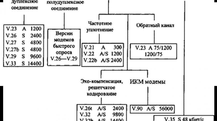
Any modem operating on a 4-wire, 2-point line uses one pair to transmit and the other to receive, and therefore can operate in duplex mode. Modems operating with 4-wire multidrop only operate in half-duplex mode. Synchronous-only modems operate on a 4-wire, 2-point, unswitched line, or over the PSTN, with one dial-up connection providing half-duplex mode and a dual-switched connection providing full-duplex mode. Asynchronous-synchronous modems operate on 2-wire lines (either leased or dial-up), and they can all operate in duplex mode. Modem Compatibility. Data transmission over telephone networks is described by recommendations of the V series of the International Telecommunication Union (Sector technical standards) - ITU-T. The compatibility check is to check the V series number specified by the manufacturer in the modem specifications. The classification of V-series recommendations is shown in fig. 2.33.
 |
The modem can operate in two modes: command and data transfer. The command mode of the modem is usually set: when the power is turned on; during the initial initialization of the modem; after an unsuccessful attempt to connect to a remote modem; when interrupted from the keyboard by pressing the “hang up” key combination (most often); when exiting data transfer mode via ESCAPE sequence. In command mode, the entire data stream entering the modem through the V.24/V.28 interface is perceived by it as a command. The mode of data transfer (on-line) is set after the modem sends a CONNECT message in the following cases: upon a successful attempt to establish communication with a remote modem; when the modem performs a self-test. In the data transfer mode, the data stream coming to the modem from the DTE is translated with conversion to the line, and the data stream from the line is translated with reverse conversion to the interface with the DTE. Functional modes of the modem. The modem is always in one of two functional modes (with the exception of periods when it switches from one mode to another): command (local) and asynchronous connection (ON LINE). The modem transition scheme is shown in fig. 2.34. When the power is turned on, the modem initializes its parameters in accordance with the configuration stored in the non-volatile memory and enters the asynchronous command mode. Only in this mode the modem accepts AT commands. On a Z-command, the modem restores its working configuration
 |
from non-volatile memory and returns to command mode, the "^-command restores the configuration according to the manufacturer's profile (default setting) and returns to command mode. The modem “picks up the phone” in auto-answer mode: a) upon receipt of an A-command; b) automatically at S1 = SO, when the counter of incoming calls (calls) becomes equal to the number set for the answer; c) upon receipt of a dialing command, when the call string ends with R. Exchange circuit functions 103, 104, 109 V.24. Consider the functions of the exchange circuits associated with the transmission and reception of data: 103 (2) TxD (transmitted data) to DCE; 104 (3) RxD (received data) to DTE; 109 (8) CD (Received Line Signal Detector) to DTE. The input stream of serial data entering the modem through circuit 103 is converted by the modulator into a modulated analog signal for output to the line (Fig. 2.35). At the other end of the line, the remote modem's demodulator receives the modulated line signal and converts it to a serial data stream for output through the receive data circuit 104.
 |
When a modulated carrier frequency is detected by the demodulator, circuit 109 changes from OFF to ON. This introduces a delay between the moment the carrier is detected and the moment the state of the communication circuit 109 changes, known as the carrier detection "on" delay. There is also a carrier detection "off" delay that occurs when the carrier at the other end of the line is turned off. Circuit 109 in the internal circuitry of the modem is necessary to fix the data exchange circuit 104 (data is received only when the circuit 109 is on). The CD turn-on delay and latching of the receive data circuit provide protection against transient bursts of line noise simulating spurious signals in the receive data circuit 104.
For an internal modem, first of all, you need to set the COM port number and IRq lines that it will use. The vast majority of internal modems are visible to the computer as an additional COM port, with the exception of soft modems with full software control, which can have an arbitrary interface.
When setting the port number, keep in mind that all modern motherboards have a built-in I / O controller that supports two serial ports, usually by default as COM1 and COM2. In BIOS Setup, for each of these ports, there can also be an Auto mode, in which the port is enabled only if there are free standard addresses and IRq lines. For example, if Auto is set for the second system port and an internal modem configured as COM2 is installed on the board, the BIOS, depending on the type and version, can either transfer the second system port to COM4 or disable it altogether.
If two ports are configured on the same IRq line (IRq sharing), then only one of them can be operated at any given time. If you try to activate both ports, neither will be able to work, except when both ports are served by a specialized program that is able to figure out which port generates which interrupt. If you set two ports to the same address, both will be inoperable.
Internal modems with Plug & Play interface do not need special configuration; it may only be necessary to set the PnP mode with jumpers if the modem also allows direct configuration of the address and IRq.
On an external modem, it may be necessary to set the operating modes with switches, if any.
You can check the correct operation of the modem port using any terminal program (Telix, Terminate, Telemate - for DOS, or the standard Hyper Terminal (Communication Program) - for Windows 95). To enter the AT&F string, the modem must answer OK. You can also use the ATZ string, however, if the default mode is set to Q1, the modem will not give an OK response to this string.
After making sure that the modem is working, you need to create a set of default parameters. To do this, enter the &Fn command with the desired configuration number, described in the modem manual; configuration with hardware (hardware, RTS/CTS) data flow control is highly desirable.
If some parameters are desired to be different from the factory configuration, their desired values are set after the &Fn command. After setting all the parameters, the &W command is entered, which writes the generated set as the default set with number 0. Subsequently, each time the modem is turned on or after the Z command is executed, this set of parameters will be set.
In order for the programs to correctly display the speed of the established connection, you must set the modem to the output mode in the CONNECT line of the real speed instead of the modem-DTE speed. This is done with the Wn command; other commands (for example, Vn) may also be required, which must be found in the description. You can check the format of the CONNECT string on most modems with the &T1 command, which establishes a test connection of the Local Analog Loopback type.
What is an initialization string and why is it needed?
An initialization string is a sequence of commands that brings the modem to a predetermined state. Typically, such a line begins with one of the &Fn commands, which sets the factory settings, followed by commands for setting the desired modes.
If the terminal program supports multiple initialization lines output sequentially to the modem, it is convenient to start the sequence with the Z command. In this case, the most common settings for all modem applications on this station are written to the active default parameter set.
In the event that one set of parameters is sufficient for all modem applications, it will be most convenient to store it in NVRAM. The initialization line in this case is reduced to a single Z command.
How can you optimize the modem and control program settings?
In the general case, the optimal setting of the modem and the program is very complex and ambiguous, however, in most cases, several of the most typical points can be distinguished:
Connection reliability. All modern modems support hardware error correction, but the factory settings allow the connection without correction if the modems failed to select a common correction protocol during the connection process. As a result, even with random interference at this moment, a connection can be established without correction, which is fraught with the appearance of a large amount of garbage at the modem output mixed with useful data and a significant decrease in the overall transfer rate. To avoid such situations, it is recommended to set the forced correction mode with the N2, N4, N6 (for most modems), &M5 (USR/3COM) commands, etc.
> - Efficiency of data compression. By default, all modern modems try to use the compression protocol. In the case of transferring unpacked data, this most often increases the overall exchange rate, however, in the case of transferring effectively packed information (ZIP, ARJ, RAR archives, collapsed distribution sets, CAB files, etc.), the V.42 compression algorithm most often runs idle, and the MNP5 algorithm tries to compress the stream anyway, causing it to increase due to overhead. Therefore, if this communication session is oriented mainly to the transmission of unpacked data, it is better to enable compression, but if large volumes of packed data predominate, and the modem supports only MNP5, it makes sense to disable compression.
Bandwidth of the interface with DTE. When establishing a connection, the modem can either set the DTE to the same transmission speed as in the channel (floating speed), or always work with the DTE at a fixed speed (fixed speed). The last case is called the port speed fixing mode (Port Locking, Baud Locking, etc.) and is the most convenient and efficient. It is recommended to set the fixed port speed to the maximum at which the system and programs retain the ability to reliably receive data, or at least twice the maximum connection speed. As a result, the increase in the transfer rate due to data compression will be compensated by the increase in the port speed, and the interface with the DTE will not be the bottleneck of the modem path.
On low-quality lines, depending on the interference spectrum, various modulation protocols can behave differently at close bit rates. For example, when connecting via the V.34 protocol at a speed of 16800 bps, the exchange rate due to error correction may be lower than when connecting via the V.32bis protocol at a speed of 14400 bps. In such cases, it makes sense to forcefully limit the possible protocols and speeds for specific communication sessions.
What is the difference between asynchronous and synchronous modes?
In asynchronous mode, data is transferred byte by byte, each byte is preceded by a start bit and terminated by one or two stop bits. Thus, the minimum unit of transmission is a byte, and the start/stop bits between bytes ensure that the beginning and end of each byte is correctly identified. This mode is convenient from the point of view of the reliability of separating signals from the line, however, it requires packing / unpacking bit data into bytes, and also reduces the transmission speed in the channel due to redundant start and stop bits (by at least 25% - 2/8).
In synchronous mode, data is transmitted bit by bit, without grouping into bytes. In this case, there is no bit grouping overhead, and the unit of transmission is a single bit. However, in order for the receiver to be able to resynchronize if part of the stream is lost, the bits are often packaged into packets of various lengths, provided with a header and a checksum. The minimum information unit in this case is the packet. Since the length of the packet significantly exceeds the length of its overhead, the overhead is much less.
All protocols for error correction and data compression establish a synchronous transmission mode between modems with packet exchange. At the same time, the exchange between the modem and the DTE most often takes place in an asynchronous mode, which, coupled with the overhead for the design and processing of packets, generates a speed difference in the channel and with the DTE. To compensate for this difference, the modem has a buffer, and flow control methods are also used.
Specialized devices (pager stations, industrial data collection systems, etc.) often use synchronous transmission between themselves and the modem, forming packets themselves and monitoring their correctness. In such cases, due to the inability of a conventional computer port to work in synchronous mode, the interaction of the computer with such devices through a pair of modems may be impossible.
Why is the connection on the internal modem broken when changing the video mode?
This happens mainly when working with a number of video adapters based on S3 chips. These microcircuits use to control the accelerator ports with addresses, the lower part of which matches the standard COM4 addresses (2E8. .2EF). With a correctly implemented PCI / ISA interface on the motherboard, access to these addresses should only be issued on the PCI bus, however, some motherboard chipsets mistakenly trans-merge them to ISA as well. If the internal modem is configured for COM4, this will cause a failure in the exchange data, disconnection, or even modem inoperability before it is re-initialized.
Why doesn't the modem recognize the busy signal?
The vast majority of modems are configured to recognize telephone signals in the US/Canada standard. The busy signal in this standard is more frequent and quiet beeps than are accepted in the Russian telephone system. As a result, if the modem's decoder does not have sufficient margin for signal duration/intensity, their correct identification occurs rarely or does not occur at all.
If the modem has the ability to adjust the sensitivity to station signals and the range of their parameters, you can try to find the appropriate values. Modems oriented to the Russian telephone network (IDC, Russian ZyXEL, Russian Courier) are initially set to the parameters of domestic signals.
For modems that do not have such adjustments, in the case when the difficulty in recognizing the "busy" signal is caused by its too loud level, you can try to attenuate the input signal by connecting a resistor with a resistance of 50 ... 500 Ohm in series with the line, but this most often has a negative effect on the quality of the connection.
Why the modem can freeze, and how to deal with it?
Like any computer, the modem's internal microcomputer can freeze for several reasons:
firmware errors
non-standard input signals or data elements against which the modem has no protection
poor quality filtering of supply voltages
electrostatic discharges or strong magnetic fields
The most common causes of freezing are the first two. In particular, in most modern modems, protocols are implemented using the finite automaton method, which provides for a large number of states and transition rules between them. With this approach, it is extremely difficult to check all possible transitions and exclude the appearance of "forbidden" states, into which the modem can fall by mistake, as well as incorrect chains of such states. As a result, under a certain combination of input conditions (types of modems in a pair, communication protocols, types of transmitted data, etc.), one or both modems can get into forbidden states. Depending on the severity of the hangup, the modem can be brought out of it either by triggering the internal timer (if any), or by removing the DTR signal, or by a complete hardware reset.
If the modem freezes regularly and there is no way to change it or at least the firmware, you can take compromise measures:
Set &D3 mode to reset on falling DTR signal. However, on most modems, the DTR signal, along with others, is analyzed by the modem's processor, and a hung processor is often unable to respond to its change. Robust modems may have a special mode in which the DTR signal is directly connected to the hardware reset circuit.
Install a hardware reset circuit in the modem that generates a Reset signal pulse, which is automatically generated when the power is turned on. The reset signal can be generated from the fall of the DTR signal, or a separate signal can be taken from some other port (COM or LPT). In the first case, only modification of the modem itself will be required, since almost all programs can reset DTR to break the connection. In the second case, you will need to launch a special program that will issue a signal to the desired port, from which the hardware reset circuit will work.
For an external modem, you can make a short-term power-off circuit that works on the same principles. The method is good because it does not require intervention in the circuit of the modem itself.
The option with the formation of an internal reset signal is of limited use in the case of an internal modem. The fact is that the internal modem always contains also a COM-port controller, the configuration of which is performed by most programs only at the beginning of work. Thus, if the reset signal is generated from the fall of DTR, then the port will also be brought to the standard state, and the program will not be able to work with it until it is reinitialized. In this case, it is necessary that the program, having detected a modem hangup, restarted in an emergency.
What is the maximum CPS achievable at a given bit rate?
Provided that there are no bottlenecks in the path (in particular, the speed of asynchronous serial ports on both sides exceeds the speed of the connection) and data is transferred everywhere at maximum speed, the maximum CPS without effective compression (for example, when transferring archives) is approximately equal to 90. .95 % of the bit rate divided by eight. For example, for a speed of 14400 bps, the CPS limit is about 1650, and for 28800 - about 3400. With the efficient operation of compression protocols, the real speed can increase two or more times (long series of repeated characters are most effectively compressed).
Different programs measure CPS in different ways during the exchange: some display only the instantaneous value calculated during the transmission of the current packet, others - the result of dividing the total number of transmitted / received bytes by the time since the beginning of the exchange. In the first case, the value varies greatly due to the influence of short-term factors, and in the second case, it is unreasonably underestimated. The most correct is to display the average CPS for a short period of time (several seconds) with the simultaneous calculation of the average CPS for the entire transmission time.
What is the difference between dial-up and leased lines?
A standard switched line is distinguished by the presence of a supply voltage (about 60 volts in Russian telephone networks) and the ability to issue and receive line and dial status signals. Accordingly, when working on a dial-up line, the calling modem generally waits for a continuous beep, then dials the number, and only after that it waits for a response from the remote modem. The answering modem, in turn, perceives the call signal (ringing), after which it connects to the line ("picks up the phone") and switches to answer mode.
> - A leased line is a permanent point-to-point connection between two subscribers. Usually this is a two- or four-wire communication line that directly connects two modems and is not connected to the station equipment in any way. In the simplest case, this can be a regular telephone cable included in the modem kit, in the most complex section of a multi-channel wire, fiber optic or radio path, which, using channel equipment, imitates a simple wired connection.
Modems that support leased line operation (command &L1) in this mode automatically disable checking for a continuous dial tone, and also automatically try to restore the connection when it breaks. To initially establish a connection, one modem must be activated as a caller (command D) and the other as a responder (command A). After that, the restoration of communication in case of a break is performed by the modems themselves in the same roles.
> - In addition, leased-line modems have learned modes, in which communication in the selected role is established automatically when the power is turned on (or after the appearance of the DTR signal). Thus, a pair of such modems immediately after power-up or the appearance of DTR creates an automatically maintained connection without the intervention of control programs, which in this case only monitors the DCD signal and / or CONNECT / NO CARRIER messages. Ideally, such a pair of modems allows you to organize a completely transparent connection, similar to a null-modem cable, in which programs are completely unaware of the existence of any additional devices in the path.
Almost all modems can work on a leased line - even those that do not support the &L1 command. It is enough that the modem does not pay attention to the presence of voltage in the line (some modems have a voltage sensor) and does not try to wait for a beep when switching to the call mode (this is provided by the X3 command). To establish a connection, the X3D commands are entered on the calling modem, after which the A command is entered on the answering modem. The only inconvenience in this case is that ordinary modems cannot automatically restore a broken connection.
The described technology can also be used when working on a dial-up line - to establish a modem connection over a channel that is already connected for a voice conversation. At the same time, modems must be connected in parallel to each telephone, their operators choose the roles of the caller / answerer for themselves, after which the caller enters the D command and, after connecting his modem to the line, hangs up. The answering operator, having heard the click of the remote modem connected to the line, enters command A and also hangs up, after which modems B A proceed to the exchange of connection establishment signals.
How to connect a modem through a blocker or AVU?
The blocker is used to separate paired subscriber lines when two subscriber lines are connected to one telephone pair, each of which uses its own polarity of supply and ring voltage, and simultaneous operation of both lines is impossible. A typical blocker is a diode unipolar rectifier that passes only the voltage of "its" polarity to the subscriber line, and also contains a transistor switch that closes the reverse current of the ringing signal (ringer). Such a blocker is designed for telephones with an inductive ring; after the completion of the action of the next half-cycle of a unipolar ringing signal, a current of the same direction appears in the bell coil, which closes through a transistor switch. Telephone sets with an electronic call and modems contain a separating capacitor, in which a current of the opposite direction occurs, and for this there is no bit circuit in the blocker. As a result, the device or modem works normally in all modes, except for call identification.
For normal operation on paired lines, blockers are produced that support devices with an electronic call. You can also independently assemble a circuit that provides the closure of the return current and the discharge of the isolation capacitor.
With the help of AVU (high-frequency multiplexing equipment), several (usually two) subscriber lines can be connected to a two-wire telephone line, which can work simultaneously. In this case, one of the lines operates in the usual mode - at a low frequency, and the rest - at high frequencies. For the transmission of call signals over a line sealed with ACD, special signals are used that are received by the ACD unit and converted into a standard ringing signal with a voltage of 110 V and a frequency of 100 Hz. A typical AVU block is also designed for devices with an inductive bell and has three connection points: two - a low-voltage line, and the third - a ringing signal output. To connect devices with an electronic call or modems, you need either an AVU unit with two connection points, or a special adapter.
If, in general, the modem works through the blocker practically without loss of quality, then speeds no higher than 9600 are usually available through the high-frequency AVU line.
> - What is FOSSIL?
Fido/Opus/SeaDog Standard Interface Layer is a standard interface layer jointly developed by Fido, Opus and SeaDog. Serves to unify the interface with serial ports in DOS, replacing and supplementing BIOS functions. In addition to the standard BIOS character wait I/O, it provides non-wait I/O, interrupt operation, buffered I/O, and so on. FOSSIL can also include an interface with a video adapter. The most famous versions of FOSSIL for DOS are BNU and X00.
FOSSIL is also useful under multitasking systems like OS/2 and Windows. The standard port virtualization tools of these systems emulate only the behavior of the port at the hardware level - byte I / O on interrupts, while emulating byte-by-byte exchange with an interrupt every few bytes creates a noticeable overhead and leads to periodic loss of bytes. Versions of FOSSIL for these systems provide DOS programs with an optimal port interface. The most famous version of FOSSIL for Windows is WinFossil, for OS/2 - SIO (Serial I/O). SIO is a development of the X00 version and, in addition to supporting FOSSIL functions, emulates the connection of two serial ports using network protocols.
Where can I get Win95/98 drivers for the modem...?
For most modems, as well as for monitors, there are no special drivers - Windows uses standard serial port drivers. The exception is modems with a non-standard interface - Soft-modems, modems with RPI, some voice modems.
However, to properly recognize a modem in Windows, an INF file is required that contains the modem's characteristics, mode setting commands, message strings, and so on. For most modems, these files are included in the package.
If Windows is not able to recognize the modem even if there is an INF file from the manufacturer, this means that either the full name of the modem type in the INF file does not match the one issued by the modem itself using In commands, or the INF file is intended for another version of Windows. If you can't find the correct .inf file on the manufacturer's website or BBS, you can try to set the type of standard modem that suits your speed. This will not affect the quality of communication - only advanced features (voice, fax, AON, etc.) will not be supported.
How to reduce the noise from the dialing relay?
The minimum solution: glue the relay with pieces of foam rubber, choosing their sizes and configuration for optimal sound absorption. This method, however, rarely gives a noticeable effect, since the vibration of the relay is transmitted to the entire board, which radiates more strongly than the relay housing itself.
The optimal solution is to unsolder the relay and connect it with segments of a thin flexible wire, and also glue the relay itself with foam rubber. In this case, the vibration will practically not be transmitted to the printed circuit board.
Cardinal solution: replace the relay with a reed switch. 5-volt RES-55A (model 0201) are well suited. If the relay has two pairs of contacts, the second of which turns off the parallel telephone, you can put two relays, or short-circuit the telephone switch. The relay can also be replaced with an electronic key, which are sold on radio markets, however, in this case, the signal-to-noise ratio may deteriorate due to the parasitic influence of the electronic components of the key.
General provisionsModems (the name comes from the merger of two words - modulator and demodulator)- These are devices that allow you to organize communication between computers located at a distance from each other. If computers are nearby, then you can organize communication between them using a serial, parallel port, USB, Blutooht. However, such communication is possible only at close distances, determined by the capabilities of the port. At long distances, the signal weakens and special devices are required that can convert the signal into a form that allows the signal to be transmitted over long distances. For this, a device called a "modem" is used - from the word MODulator-DEModulator. The modulator allows you to convert a digital signal to analog, and the demodulator allows you to do the reverse conversion, that is, convert from analog to digital.(in a more precise sense, modulation is a change in the characteristics of a carrier signal (usually low-frequency periodic oscillations) by a high-frequency control signal that allows you to transmit the necessary information). Demodulation is the selection of an information signal from a set of carrier and information signals). Fax works on almost the same principles, so modems that are available with facsimile capabilities are called a fax modem. Modems can be internal (inserted into expansion slots), external (connected to COM, LPT, USB ports or a network cable to the RJ-45 connector of a computer network card, usually have an external power supply), built-in like a laptop or in the form of a connection card to laptop PCMCIA connector(the latter is also called an expansion card PC Card and almost obsolete. The standard currently used express card with bus connection USB and PCI Express ). Recently, wireless modems (called a module or gateway) have become widespread, using communication lines of cellular operators (the most famous are USB modems) . The principles of operation of all devices are the same.
Modems can be analog And digital. Analog modems were the first to be used (dial-up). Due to the fact that the data transfer rate through these modems was not high (up to 56 Kbps), they began to switch to digital modes (with an operating frequency from 4 kHz to 2 MHz and, accordingly, a speed of up to several megabits / s). In addition, when transmitting data via an analog modem, you cannot carry on a conversation.
Most users used the telephone network for data transmission. In order to be able to use the digital mode of transmission, it is necessary that both the sender and the recipient have a digital exchange. In addition, there should not be paired telephones and burglar alarms on the telephone line. Until now, some users use analog modems.
Main characteristics of modems:
- interior or external. An internal modem is a card that plugs into a slot on the motherboard. Such a modem is inserted like a regular card, but you need to connect the wires as indicated below. An internal modem is usually cheaper than an external one. But it does not require space on the table, does not take up the serial port of the computer.
External modems (new) plug into the USB , PCMCIA or ExpressCard slot and do not require additional power as they get it from the slot.
An external modem (older ones) is connected to the serial port and is located in a separate case. This type requires connection to the electrical network through a transformer. Its advantages include the fact that it does not take up an expansion slot, making it easy to transfer it from one computer to another.
Supported standard And transmission speed;
Size of RAM or flash memory.
Additional features of modems: digitization of voice and its conversion into an analog signal for conversation when transmitting data; Fax; automatic identification of the caller's number; answering machine; electronic secretary and other features that telephone sets have.
As a rule, a modern modem has the following phone capabilities, which we present. These are: negotiations with several subscribers; temporary muting of the microphone; turning on external speakers; memory for subscriber numbers; repeated call of the subscriber; auto redial; automatic identification of the number; remembering the calling numbers and the time of the call; detection of the second call during a conversation; protection from unwanted calls; recording received messages; answering machine; remote control; on the phone panel there may be buttons with functions: auto-repeat, listening to left messages, turning off the phone, turning off external speakers, etc.; on the telephone panel there may be indicators that determine the operating mode, pick up the handset, etc.; there may be a display with data on incoming and outgoing calls, talk time, etc.; voice dialing, the user calls the name of the subscriber by voice, and the modem connects with his number; speed dialing, dialing a number using one or two keys; auto attendant, answering incoming calls when talking with another subscriber; collection of statistics on the number of calls received, their numbers, conversation time during the day, etc.; other functions such as dialing certain number at certain times of the day, alarms, etc.
If the modem freezes, you can restore its performance by resetting the power supply (remove the external one and reinsert it), and you do not need to turn off the computer. In addition, it has an indication by which you can determine the status of the modem.
digital modems.
Several are currently in use formats: ADSL, HDSL, IDSL, ISDN, HPNA, SHDSL, SDSL, VDSL, WiMAX and wireless modems using wireless communication (Wi-Fi). They are often referred to as xDSL (Digital Subscriber Line).
ADSL(Asymmetric Digital Subscriber Line - asymmetric digital subscriber line) appeared in 1987 and is one of the very first and most common digital data transmission format. Allows you to send data from the user to the network at a speed of 16 to 640 kbps (according to the standards 0.5, 0.8, 1.2, 1.3, 3.5 Mbps, and receive data at a speed of 1.5, 0.8, 5, 8, 12, 25 Mbps sec). Since the user is normally receiving rather than sending data, this split of rates is not perceived by the user, except in video communications. Therefore, over time, other types of formats began to appear using coaxial cable ( cable TV, speed up to 100 Mbps) and an Ethernet connector (LAN up to 1 Gbps). In a number of European countries, the ADSL standard has become the standard by which every resident gets access to the Internet.
An ordinary telephone line uses frequencies from 0.3 to 3.4 kHz for transmission, for an ADSL modem the lower frequency for the outgoing stream is 26 kHz, and the upper one is 138 kHz, and for the incoming stream from 138 kHz to 1.1 MHz. Thus, you can talk on the phone and send and receive data at the same time.
However, the first modems did not allow comfortable enough to talk on the phone, since the high-frequency part of the modem introduced extraneous noise into the telephone conversation (and vice versa, the conversation introduced distortions into the data transmission). To avoid this, they began to use a frequency filter (Splitter - frequency separator), which passed only low frequencies to the phone.
HDSL (High Data rate digital S ubscriber Line) was developed in the late 80s. It uses not one, but two pairs of wires and has a speed of either 1.5 Mbps (American standard) or 2.0 Mbps (European standard) and allows you to transmit a signal up to 4 kilometers, and in some cases up to 7 kilometers. Mainly used for organizations.
IDSL(ISDN Digital Subscriber Line - IDSN digital subscriber line) allows you to transfer data at a speed of 144 Kbps.
ISDN(Integrated Services Digital Network - a digital network with service integration) appeared in 1981 and has a data transfer rate of 64 Kbps.
HPNA(Home Phoneline Networking Alliance - the name of the unified association of non-profit industrial companies) works with either standard telephone or coaxial cable. The latest standard (3.1) allows you to transfer data at speeds up to 320 Mbps, according to standard 2.0 - 10 Mbps.
SHDSL (Symmetric High-speed DSL - symmetrical high-speed DSL) allows you to transfer data over one pair of wires at speeds from 192 Kbps to 2.3 Mbps, and two pairs twice as much at a distance of up to 6 km.
SDSL(Symmetric Digital Subscriber Line - symmetrical digital subscriber line) uses one pair of cables with speeds from 128 to 2048 kbps. Operates at a distance of 3 to 6 km.
VDSL(Very-high data rate Digital Subscriber Line - ultra-high-speed digital subscriber line) has a high data transfer rate of 13 to 56 Mbps from the network to the user and 11 Mbps in the opposite direction at a distance of up to 1.2-1.4 km.
WiMAX(Worldwide Interoperability for Microwave Access) is a wireless communication in the wavelength range from 3.5 to 5 GHz according to the 802.16-2004 standard (or fixed WiMAX) and 2.3-2.5, 2.5-2.7, 3.4-3.8 GHz according to the 802.16-2005 standard (or mobile WMAX). It has many similar parameters with Wi-Fi, but differs in that it can transmit a signal over a long distance and, moreover, is somewhat more expensive.
Bluetooth(translation - blue tooth) was developed in 1998 and is used for wireless communication with a computer in the license-free range of 2.4 - 2.4835 GHz. It has no connector and is located inside a computer (device), used to transfer data using radio waves between various types of computers, cell phones, printers, cameras, keyboards, mice, joysticks, headphones, MFPs, scanners and others.The essence of the method lies in the fact that in a certain range, the frequency is pseudo-randomly changing stepwise 1600 times per second. Such a change in frequency occurs simultaneously for the receiver and transmitter, which operate synchronously according to this scheme.Devices can be located at a distance of up to 200 meters from each other, depending on the obstacles between them (walls, furniture, etc.).
The transmit/receive device is inside the computer and is not visible. If the computer does not have such a device, then you can connect an external device via the USB connector, which allows you to work with this type of data transfer.
There are standards: 1.0 (1998), 2.0 EDR (2004) with a data transfer rate of 3 Mbps, in practice about 2 Mbps, 2.1 (2007) with the use of energy-saving technology, simplified communication between devices, has also become more secure, 2.1 EDR requires even less power, further simplifies the connection of devices and increases reliability, 3.0 HS (2009) with transfer rates up to 24 Mbps. 4.0 became used in the iPhone in 2011, allows you to transfer data at a speed of 1 Mbps. in portions from 8 to 27 bytes.
There are profiles for this standard, which are a set of features. In order for devices to work according to a specific profile, both devices must support this profile. For example, A2DP (two-channel stereo audio transmission), AVRCP (standard TV function transmission), BIP (picture forwarding), BPP (text, e-mail forwarding to printer) and so on.
WiFi used to create a wireless network. Developed in 1991 by NRC Corporation and [email protected], is supported by the Wi-Fi Alliance and complies with the IEEE 802.11 standard. Used to connect to the network (local and Internet) computers and cell phones.
The transmit/receive device is located inside the computer and is not visible. If the computer does not have such a device, then you can connect an external device via the USB connector, which allows you to work with this type of data transfer.
The following standards are available: 802.11a uses frequencies of 5 GHz, providing speeds (in theory) up to 54 Mbps; 802.11b uses frequencies of 2.4 GHz, providing speeds (in theory) up to 11 Mbps. (practically not used); 802.11g uses frequencies of 2.4 GHz, providing speeds up to 54 Mbps. (the most common); 802.11n uses frequencies of 2.4 and 5 GHz, providing speeds from 150 to 600 Mbps. (newly developed, starting to gain momentum). In this standard, the range of data transmission is increased, communication is less affected by barriers. This standard uses MIMO technology (Multiple Input Multiple Output - multiple input, multiple output), which allows the use of reflected waves from walls. If the device has one antenna, it can operate at a speed of 150 Mbps, two antennas - 300 Mbps, three - 450 - Mbps, four (not yet available) - 600 Mbps. However, the declared data transfer rate differs from the actual one. So instead of 300 Mbps, it turns out about 100 -130 Mbps (since half of the transmitted information is service characters), which is also enough for work. And in the presence of walls, the speed still drops, for example, for three walls it will drop to 50 Mbps.
Since some household appliances operate at 2.4 GHz (such as a microwave oven), they may cause interference. Therefore, it is desirable to have a device that operates at two frequencies: at 2.4 and 5 GHz.
There are also cable modems for connecting to a cable TV channel.
Typically, digital modems may contain elements that are used as Gateway between the local network and the Internet: a router, a firewall, and so on.
Modem indicators
There may be the following indicators:
AA(Auto Answer - auto answer) - auto answer mode that provides a response to the subscriber's request in automatic mode;
CD(Carrier Detect - carrier or DCD detection) - lights up during a communication session;
CTS or CS(Clear To Send) - the modem is ready to receive data from the computer. Turns off while receiving data;
DATA– lights up during data transmission;
DC (Data Compression) data ;
FAX– when the modem is operating as a fax;
HS(High Speed - high speed) - lights up when the modem is operating at maximum speed;
EU (Error Control or ARQ) - error correction mode;
MR(Modem Ready - modem readiness or DSR) - indicates that the modem is connected to the power supply and is ready for operation;
Oh(Off Hook - off-hook) - glows when the handset is hung up;
ON(PWR) - power indicator;
PWR (PoWeR) – power on;
RD(Recieve Data - receiving data or RX or RXD) - indicates that data is being sent to the computer;
SD(Send Data - sending data or SX or TXT) - indicates that data is being received from the computer;
TEL– lights up when the handset is off-hook on a telephone connected in parallel;
RTS (Request To Send) - the modem is ready to receive data from the computer. Lights up when waiting for data from the computer, goes out during data transfer;
TD (Transmit Data or TXD) – lights up or flashes when data is being transferred from the computer to the modem. May light when data is being transmitted at the maximum transfer rate;
TST (TeST) - flashes during testing;
TR(Terminal Ready - device readiness or DTR) - lights up when receiving a control signal;
USB– lights up when the modem is connected to the computer via the USB bus.
There may also be a volume control on the modem case.
On the back external modem may have connectors with icons:
AC IN – connecting the power adapter;
LINE – connection to a telephone line;
ON / OFF – modem on/off;
PHONE – connection telephone set;
RS -232 – connector for connecting to a computer serial port;
USB – socket for connecting to the USB bus.
Analog modem
Data transfer. Telephone lines are adapted to analog signals. Due to the fact that human speech has a range of 30 Hz to 10 kHz (music has a larger range), to save money, the telephone line passes a signal from 100 Hz to 3 kHz. It is this limitation that binds the possibilities for data transmission at high speeds. Computers can be connected not only through a telephone line, but also using radio waves and infrared radiation. In this case, wires are not needed.
Ultimately, the data sent on the parallel channel is serialized at the serial port with start-stop bits, transferred to the modem, where it is modeled, that is, superimposed on the carrier frequency of the signal transmitted over the line, then sent to another modem. Next, they are digitized, sent to the serial port, where they are converted to parallel form, and then sent to the processor for processing.
Digital data is sent bit by bit, and the sending can be of two types: synchronous and asynchronous. In a synchronous transmission, a data packet consists of a header containing the destination address, the data itself, and a checksum. An asynchronous transfer sends a start bit, 8 data bits, possibly an even parity bit, and a stop bit indicating the end of the transfer. This type is used in a serial link.
In addition, three modes can be used for data transmission: full duplex, in which data is transmitted in both directions simultaneously, half-duplex, in which data can be transmitted in both directions, but in one direction at a time, and simplex, in which data is transmitted only in one direction.
Data transfer from modem to modem and from modem to computer has a different speed, so that the data is not lost, the modem has a buffer where the received data is stored.
Some modems compress data before sending it, and another modem decrypts the data when it receives it. There are files that have already been compressed, so this method may not give you the best transfer experience. To avoid data loss, the data transfer rate from the modem to the computer must be several times higher than between modems, which is implemented in practice.
When transmitting data, the unit is often used baud, which is sometimes confused with bps. In fact, they are different sizes. 1 baud is one character sent per unit of time, and it can be not only data, but also control signals. A character can be multiple bits. If the signal consists of two types: 0 and 1, then the symbol means 1 bit, if 512, then 9 bits (2 9 = 512). When transferring data at a low speed, 1 baud is approximately equal to 1 bit / s. At a high speed, the modem sends data already at several frequencies, so not one, but several bits are transmitted at each moment of time, that is, the speed measured in bits / sec, and not baud / sec, will be several times higher than the baud rate . Often quoted baud rate refers to bits/sec.
When transmitting via a modem, you can roughly determine how long it takes to transmit by dividing the transmission rate by 10, for example, if the transmission is at 28,800 bps, then approximately 2,880 bytes or characters will be transmitted per second (28,800/10= 2800).
The modem connects to the computer's serial port and works with serial data. Typically, a modem is used to work on the Internet, but it can also be used for direct communication between two arbitrary computers. Modems are also used as fax machines to send fax messages. They may have a built-in adapter for creating voice messages in answering machine mode.
When connected, the modem sends out signals that are also output to the speakers and can be heard as a continuous, changing sound for several seconds. The receiving modem determines the standard by which it can operate, and also makes clock frequency settings, that is, it performs phase simulation. After that, the speaker is turned off, but the signals continue to arrive, in particular, they can be heard through the parallel phone.
Modems are of two types: internal and external. The internal ones are made in the form of expansion cards and are inserted into the motherboard connector, the external ones have their own case and are connected to the serial port using a cable. The latter types of modems can be connected via the USB bus (and sometimes receive power from the computer), so they are used while the computer is running, free up a connector, and have other advantages. When connecting a modem to a serial port for high-speed models, the port must also be high-speed. For example, 56Kbps modems require a serial port speed of 115Kbps. The higher port speed is needed because it also sends control signals between the computer and the modem that are not sent over the telephone line. If the port does not support high speeds, data may be lost. External devices can be turned off by turning off the power supply, and internal devices can only be turned off when the computer is turned off, which is inconvenient when the modem freezes.
Modems can be divided into two categories: the first type (Class2) has an internal processor that processes the data, the second type has the data processed by the central processor (Class1), they are also called Windows modems, somewhat cheaper than the first type. Such a modem, if the processor is old, can greatly slow down the computer, but if the user rarely accesses the Internet and sends only a small amount of e-mail from time to time, then this is acceptable. It is quite advisable to use it even if the computer has a powerful processor.
Often the modem is characterized protocol with which he works. Exist signal modulation protocols, error correction protocols, data compression And facsimile operations (fax). The modem has several protocols for each of these types. Error correction protocols include V.42, MNP2-4, MNP10, data compression - V42bis, MNP5.
One of the main characteristics of the modem is the data transfer rate, and indicated maximum speed can be 33.6 or 56 Kbps for modern devices. If 33.6 Kbps is specified, then the entire bandwidth is used and data is transmitted in both directions at 33.6 Kbps. if the line allows it. If the line does not allow this, then a transition to a lower speed occurs. Speed 56 Kbps. provides receiving data at a higher speed than when sending them, since there are more frequencies for reception than for transmission, however, transmission from the modem is carried out at a lower speed.
In addition, it is necessary that both modems have the same characteristics, otherwise the data transfer will not reach the maximum speed. To do this, before buying a modem from a provider, you need to clarify the type of modem with which it works best. Below is a table of correspondence between some protocols and the transmission speed over it.
The prefix bis means that the standard has been revised. Starting with a speed of 14400, all protocols are duplex, that is, they transmit messages in both directions at the same time. Not only the names of the standards that define the data transfer protocol, but also other types of protocols can begin with the symbol V, for example, V.24 contains a list of certain signals between two modems, V.25bis is a command language for managing a modem, etc., there are other names, for example, MNP, sometimes starting with the symbol V, but then there are not numbers, but symbols, for example, V.FC.
The following MNP protocols are in effect: MNP1 And MNP2- outdated and not currently used; MNP3– provides synchronous transmission; MNP4- transmits data in synchronous mode in packets from 32 to 256 bytes of data, while the packet size depends on the quality of the telephone line. For a lower quality line, a smaller package is used, for a higher-quality line, a larger one; MNP5- provides synchronous mode, while data compression is used, has two algorithms for compressing repetitive messages; MNP6- provides synchronous mode, also uses data compression; MNP7, MNP8, MNP9- provides synchronous mode, while using more advanced compression methods; MNP10- used in case of low-quality data line. At the start of work, it sets the lowest speed, and if the line is able to work with high gear, then the speed increases.
There are also the following protocols:
Xmodem- the protocol was issued in 1977. The transmitting modem sends a special NAK signal, then, upon reception, the receiving modem issues a NAK signal until it receives a data packet that consists of a start of data character (SOH), a block number, 128 bytes of data, and a checksum (CS) . When data is received and checked for correctness, a checksum signal is sent that the data was received (ACK), and if received incorrectly, a signal (NAK) is sent. If there are multiple failed data transfers, the session is terminated. At the end of the transmission, an EOT character is sent, indicating the end of the session.
There are modifications of this protocol, for example, in Xmodem CRC the checksum has been increased to 16 bytes, which increases the reliability of transmission, Xmodem 1k– data block size increased to 1 kilobyte, Xmodem G- transmits data, and the checksum is at the end of the file, not the data block.
Ymodem- based on the Xmodem protocol, with a transfer size of 1 kilobyte, transfers the file name and its attributes. In addition, the first block contains information about whether the following files are available for transfer.
Kermit- uses data packets up to 94 bytes, mainly used in Unix systems.
Zmodem- transfers data from 64 to 1024 bytes in size with their compression. On failure, sends data from the point at which the failure occurred.
Bimodem– further development of the Zmodem protocol with the ability to send data in two directions simultaneously.
Sometimes you may need modem commands, for example, to test it. Below is a list of some modem commands (note that modem modifications may have a different set of commands):
ATA- readiness of the modem to work;
ATADP number– pulse telephone number dialing;
ATADT number– tone dialing of a telephone number;
ATW– carrier waiting;
ATMx– loudspeaker operation, where 0 is off, 1 is on;
ATLx– loudspeaker volume from 0 to 7;
ATQx– modem messages about command execution: 0-enabled, 1-disabled;
ATHx– 0-disconnect the modem from the line, 1-connect;
ATZ- restoration of the original mode of operation;
AT&W– writing the current modem parameters to memory;
ATSx=value– determination of modem characteristics;
+++ - switching the modem to command mode;
A\- repeat the last command.
When transmitting data over a modem, special protocols are used for data compression, for faster transmission, and error correction methods. These standards are referred to as MNP (Microcom Networking Protocol), as well as some of the standards beginning with the letter V (V.41, V42, and V42bis).
For data transmission, a special protocol is used, that is, the rule by which data is transmitted and received. For normal operation, it is necessary that both modems (sending and receiving) can work with these protocols. With data correction methods, in addition to them, a special CRC combination is sent, which serves to determine errors. Upon receipt, the data is checked, that is, the CRC blocks (calculated and check) are calculated and compared, and in the case of normal operation, a signal is sent that the data was received correctly.
Remarks. The country code in the computer is the same as the international phone prefix. The phone number consists of the following digits: Country code (10 for Russia), + region code (495 or 499 for Moscow) + PBX number (3 digits) + internal PBX phone number (4 digits)
If you experimented with the modem and it does not work, then to reset the parameters, you can restart the computer, while turning the modem off and on, or enter the AT&F command, and enter AT&V to determine the modem parameters.
The transmission of textual information over telephone channels is called dayphone.
Modems contain in itself: I / O port adapter for working with a telephone line; I / O port adapter for working with a computer; a processor that modulates/demodulates the signal and provides a communication protocol; memory where the microcircuit control program is stored, modem parameters are supported, and RAM; a controller that manages communications with the computer and modem components.
The modem may have some of these components, and the missing part will be modeled by the central processor, for example, the controller. Such modems are called software.
The most important characteristic is the data transfer rate. More recently, the standard was 14.4 Kbps (of course, there were lower speeds), then devices appeared that allowed information to be transmitted at a speed of 28.8 and 33.6 Kbps. Now the maximum transfer rate has reached 128 Kb / s and provided the maximum possibility of transmission over the telephone network.
Of course, devices that operate at 33.6 KB can also operate at slower speeds, namely 28.8 and 14.4 KB/s, but not vice versa. So, if at one end there is a modem that provides a transfer rate of 28.8 Kb / s, and at the other - 14.4, then the transfer will occur at a speed of 14.4 Kb / s.
Installing the modem
Modem installation. Installing a modem, as a rule, is not a big problem, since after installation the operating system itself finds it and installs a standard driver. If a driver is attached to the modem, then it is advisable to install it, since compared to the standard driver, it provides additional features.
To install, you need to perform the following sequence of actions:
Turn off the computer (if you are connecting an internal modem or an external modem to the serial port);
If it is an internal modem, install it as an expansion card. At the same time, hold the board by the edges, without touching the conductors and microcircuits on the boards. If this is an external modem, then connect to the serial port or USB port. If the number of pins in the serial port connector does not match, an adapter will be required, as one of the ports may already be occupied;

If the modem has one output for the phone, then you need to connect the wire at one end to the modem, and the other end to the telephone socket. In this case, you can use a special type of outlet that has two outputs: one for the phone, the other for the modem. The view of such a socket is shown in the figure on the right, it has two such types of connector.
One coincides with the standard in force in our country, and the second - with the one adopted in the West, it is available in many modems sold.
You can use a special splitter, which has one connector at one end and two at the other. One connector is installed in the telephone set, the wire to the telephone socket and the wire to the modem are connected to the other two.
If the modem has two telephone jacks, then you need to connect the wire from the telephone socket to one (the inscription near the line connector), the other to the telephone set (the inscription phone). If there is no inscription, then look at the back of the modem, where there may be a pin diagram, or refer to the documentation. If the connection is not made correctly, the modem will not work. In this case, change contacts. The external modem must also be connected to the network via the power supply. To install an internal modem, use the description of installing boards in the system unit;
After installation, turn on the computer and install the software that came with the modem.
Notebooks have one output for connecting to a telephone line. While working with the modem, it is better not to use a parallel telephone or connect it through the appropriate socket on the modem, otherwise interference from the telephone line may occur, noise may appear.
In the Windows system, after installing the modem, a message will appear on the screen stating that the system has detected a new device, after which the system itself will try to determine its characteristics. Follow the instructions that came with your modem. It is necessary to make the correct installation so that there are no conflicts due to the use of system resources.
Installation modem is made in the same way as other devices. If the modem supports the Plug & Play standard, then when you turn on the computer, a “setup wizard” will appear on the screen, which, using questions and answers, will help you install the modem. If the modem does not support the Plug & Play standard (for very old models), then you need to use the mode: Start → Settings → Control Panel → Modems (2) → Properties (modems) → add → (do not detect modem type) Next. If there is a disk for the modem, then you need to use the “Install from Disk” mode or, if it is not available, select the manufacturer (if it is unknown, then “Standard modem types”) and Model → Next → after selecting the appropriate model, click Next → (select desired port) Next .
One of the most important parameters that needs to be set is the type of dialing, which must be pulsed, since we do not use another type in our country. To install it, in the Properties: Modems: General window, click "Connection settings", where select pulse dialing.
To check, whether the installation was done correctly, use the mode: Start → Settings → Control Panel → System (2) → Devices, where there is a list of devices. If there is a plus sign next to the name "Modem", then you need to click on this icon to expand the list of modems. Then you should make sure that there are no question and exclamation marks near the installed device.
Modem settings can be look And change through: Start → Settings → Control Panel → Modems → Properties → General, where the port changes, the speaker volume, the maximum speed is indicated. In this case, the maximum speed is meant between the modem and the computer, and not between the modems. Usually, the maximum speed is set, and in case of poor communication, it is reduced.
Other questions
In general, communication channels are divided into:
Analogue (for example, telephone), through which information is transmitted in the form of a continuous signal;
Digital, transmission of digital (discrete or pulse) signals
or
simplex,
half duplex,
duplex
or
Switched, created at the time of information transfer, are then turned off;
Unswitched (dedicated), long-term dedicated
or
Low-speed (telegraphic) with a speed of 50-200 bytes / sec.;
Medium-speed (telephone) with a speed of 300-56,000 bytes / sec.;
High-speed, over 56,000 bps.
To transfer data from high speed twisted pair wire (twisted together), coaxial cable (as in a television antenna), fiber optic (from glass fibers) and a radio channel (through radio waves) are used.
Radio waves can be ultra-long (3-30 kHz), long (30-300 kHz), medium (300-3000 kHz), short (3-30 MHz), ultrashort (30 MHz-3 GHz), submillimeter (300-6000 GHz).
When transmitting data, several types of modulation are used: frequency (V21), phase (V22), amplitude and quadrature amplitude modulation, in which the phase and amplitude change, which is more noise-resistant than the previous ones, so it is used in the V22.bis standard and higher.
The protocol also contains the ability to split messages into blocks, restore communication, correct errors, etc. These include Xmodem, Ymodem, Zmodem, Kermit, and others. The most common is Zmodem.
network cards serve to connect a computer to a network of computers and are an intermediary between a computer and a network for data transfer. The network card has its own processor and memory. The main characteristics of a network card are the bus to which it is connected, the size of the memory, the bit depth of the card (8, 16, 32 bits), and the types of connectors for thin and thick cables. Network cards require the setting of an interrupt line (often 3 or 5), a DMA channel, a memory address (C800).
Network cable may be of several types:
twisted pair. It consists of several twisted copper conductors in one cable, which can be unshielded (UTP) or shielded (STR).
coax cable consists of a central and shielding wires, between which there is insulation. There are two varieties of this cable: thin (0.2 inch thick) and thick (0.4 inch thick).
Fiber optic cable consists of two wires consisting of light fiber fibers. It has a large throughput, but is very expensive, so it is rarely used.
When using a cable, pay attention to the characteristic impedance, often 50 ohms. When laying, you need to have cables of the same brand, preferably one manufacturer. After laying a thin cable, connectors are installed, for example, Russian-made (CP50) or crimp BNC connectors. A plug is installed at the ends and one of them must be grounded.
The thick cable is laid through the transceivers, and one transceiver is used to one computer, and at the ends of the cables leading to the computer, there must be 15-pin DIX connectors (or AUI). At the end of the cables are installed: N-terminators, one of which is grounded. To increase the length of the local network (for a thin cable, it cannot be more than 185 meters), repeaters are used (Repeater - repeater).
A twisted pair cable is used together with a hub or hub (Hub), from which a cable no more than 100 meters long is laid to each computer. At the ends is an RJ-45 connector, which is similar in appearance to a telephone jack, but has 8 pins (not 4). Hubs can have a different number of ports, for example, 8, 12, 16, corresponding to the maximum number of connected computers.
When the modem is running fax, he works by his own standards. When sending faxes at 14.4 Kbps, V.17 (14400), V27 ter (4800), V29 (9600) and T.30 are used for the protocol itself. When transferring a sheet image, the following modes with resolution for fax transmission can be used: standard (Standard) - 100x200 dpi; high-quality (Fine) - 200x200 dpi; high quality (Superhigh) - 400x200dpi; photo mode (Photo) transmits 64 shades of gray.
A modern modem supports most standards, at least those that operate at less than the maximum speed of this modem.
In addition to ordinary modems, there can be very specific modems, for example, cable ones, when the signal is transmitted through tv cable. In this case, the cable is connected to a special socket, which has a connector for the TV and for the serial channel of the computer. Work on cable networks allows you to transfer data at high speed. However, over time, as the number of users increases, throughput per user may become low. And now, while there are few users, they give a small number of users the big benefits of working on the Internet.
Can be used satellite devices, while users send a message to the provider via phone, which pages he wants to receive, and receives them via satellite.
Currently, more and more information is being used mobile connection. In this case, the modem is connected to the mobile phone through a special cable.
In our country, the most widespread in data transmission is voice and digital, there is a standard GSM- Global System for Mobile Communication, which can be translated as "a global system for mobile communications". The essence of such a standard is that all transmitted information is divided into so-called frames, divided into eight intervals. Depending on the busyness of the line, one interval or another can be used. But this method of mobile communication is intended primarily for the transmission of voice messages, which have priority over digital data. Ultimately, the data transfer rate does not exceed 9.6 Kbps.
Other standard GPRS(General Packet Radio Service - general packet radio service) allows you to increase this speed to 50 Kbps, and theoretically it can reach 100 Kbps. Unlike GSM, here, for sending information, it is possible to use other time intervals in the frame, up to all eight, and this circumstance increases the speed of sending data. In addition, this option of mobile communication provides a reduction in user costs, since the volume of transmitted information is paid, unlike GSM.
GPRS devices are divided into three classes according to their capabilities:
Class A. Such devices in each unit of time are capable of simultaneously transmitting both types of information - voice and digital.
Class B. These models allow you to work alternately, either with digital data or with voice.
Class C. Only digital data is sent here.