How to test a solid capacitor. How to check the performance of a capacitor using a multimeter
Read also
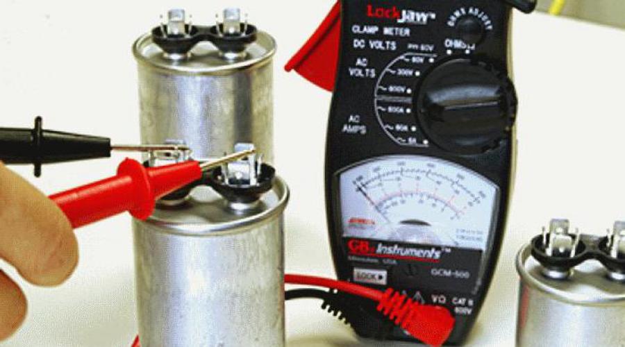
The cause of electrical breakdowns is often the failure of a capacitor. To carry out repairs, you need to know how to test a capacitor with a multimeter. You will also need a soldering iron as a tool, since the part will have to be desoldered from the board.
Polar capacitors can be easily checked using an ohmmeter. If the resistance of the part is infinitely large (one is lit in the left corner), this means that a break has occurred.
Capacitor Capacitance Testing
An electrolytic capacitor dries out over time and its capacitance changes. To measure it, you need a special device. How to test an electrolytic capacitor with a multimeter? The device is connected to the part, and the required measurement limit is selected using a switch.

When an overload signal appears on the indicator, the tool switches to lower accuracy. The capacitance of non-polar capacitors is measured similarly.
Types of capacitor faults
- Capacity has decreased due to drying out.
- Increased leakage current.
- Active losses in the circuit have increased.
- Insulation breakdown (short circuit of plates).
- There is a break inside between the plate and the terminal.
Visual inspection of capacitors
Malfunctions occur due to mechanical damage, overheating, power surges, etc. Most often, the capacitor fails due to breakdown. It can be seen by the following defects: darkening, swelling or cracks. Domestic parts may cause a small explosion when they swell. Foreign capacitors are protected from it by a cross-shaped slot at the end of the part, where a slight swelling occurs, visible to the eye. A part with this malfunction may appear normal, but be inoperable.
To check, the element is desoldered from the board, otherwise it is impossible to test it. The check can be done using the resistance map on the board, but for specific model it is not always available at hand, even during service.
Diagnosis of faults of non-polar capacitors
The resistance of a non-polar capacitor is measured. If it is less than 2 mOhm, there is a malfunction (leakage or breakdown). A working part usually shows a resistance of more than 2 mOhms or infinity. When taking measurements, do not touch the probes with your hands, since the body resistance will be measured.
Breakdown testing can also be carried out in diode test mode.
It is impossible to detect a break in small capacitors using an indirect method. How to check the capacitance of a capacitor with a multimeter in such a situation? Here you need a device that has the necessary function.

Checking electrolytic capacitors
There are slight differences in how to test a capacitor with a multimeter in ohmmeter mode. Polar capacitors are tested similarly, but their measurement threshold is 100 kOhm. As soon as the device is charged and the reading exceeds this value, you can judge that the part is working properly.
Important! Before checking the functionality of the capacitor with a multimeter, it should be discharged by connecting the leads. High-voltage parts from power supplies are connected to an active load, for example through an incandescent lamp. If you leave the charge, you can damage the device or get a noticeable discharge by touching the terminals with your hands.
Probes are connected to the capacitor to show the increase in resistance of a working part. The black probe with negative polarity is connected to the negative conductor, and the red one is connected to the positive conductor. On the surface of an electrolytic capacitor, minus is indicated by a white stripe on the side.

It is more convenient to carry out such a check on pointer instruments, since the size of the capacitance can be judged by the speed of movement of the pointer. You can test serviceable parts with known indicators and create a table from which the capacitance is approximately determined based on the speed of voltage drop.
After the capacitor is charged during testing (usually up to 3 V), the voltage value across it is measured. If it is 1V or less, the part needs to be replaced because it has not charged. After checking, the serviceable capacitor is soldered back, but it must first be discharged by shorting the legs with a probe.
The guarantee for an electrolytic capacitor means that during a given time the value of its capacitance will not exceed the specified limits, usually not exceeding 20%. When the service life is exceeded, the part remains operational, but its capacity is different, and it must be monitored. How to check the capacitor with a multimeter in this case? Here the capacitance is measured with a special device.
A break is difficult to detect with an ohmmeter. Its sign is the absence of changes in readings in ohmmeter mode.
How to test a capacitor with a multimeter without desoldering
The difficulty of checking a capacitor without dismantling is that it is adjacent to elements such as transformer windings or inductors that have little resistance to direct current. Measurements can be made in the usual way, when there are no low-resistance parts nearby.

Conclusion
A home DIYer should know how to test a capacitor with a multimeter. There are direct and indirect methods for this. We should not forget about the need to discharge the capacitor before each measurement.
Don’t know how to test a capacitor for functionality with a multimeter? The technology for testing this circuit element is quite simple; the main thing is to know how to use the tester and follow a few simple recommendations. So, next we will tell you which devices are easiest to use to determine the health of a capacitor and how to do it correctly.
Preparatory work
Before checking the serviceability of the capacitor, it is necessary to discharge it. For this, it is best to use a regular screwdriver. With the sting, you must touch two terminals of the barrel at the same time to create a spark. After a small flash, you can move on to checking the functionality.
Method number 1 – Multimeter to help
If the capacitor does not work, then it is best to check its functionality with a multimeter or tester. This device allows you to determine the capacity of the “container”, the presence of a break inside the barrel or the occurrence of a short circuit in the circuit. We have already told you about this, so we recommend that you first read this article. If you know how to work as a tester, then things are much simpler.
First of all, you must determine which capacitor is in the circuit: polar (electrolytic) or non-polar. The fact is that when checking a polar product, polarity must be observed: the positive probe must be pressed against the positive leg, and the negative one, respectively, against the minus leg. In the case of a non-polar version of the part, there is no need to observe polarity, but it will also have to be checked using a different technology (we will discuss this below). Once you have decided on the element type, you can move on to verification work, which we will now consider in turn.
Measuring resistance
So, first you need to check the resistance of the capacitor with a multimeter. To do this, unsolder the barrel from the diagram and, using tweezers, carefully move it to a work surface, for example, a free table.

After this, we switch the tester to the continuity mode (resistance measurement) and touch the leads with the probes, observing the polarity.
Please note that if you confuse a minus with a plus, the performance check may fail, because the capacitor will immediately fail. To prevent this from happening, remember the following point - manufacturers always mark the negative contact with a tick!
After you touch the legs with the probes, the first value should appear on the display of the digital multimeter, which will immediately begin to increase. This is due to the fact that the tester will begin to charge the capacitor upon contact.

After some time, the maximum value “1” will appear on the display, which indicates the serviceability of the part.

If you just started checking the capacitor with a multimeter, and you get a “1”, it means there is a break inside the barrel and it is faulty. At the same time, the appearance of a zero on the display indicates that something has happened inside the Conder. 
If you decide to use an analog multimeter (pointer) to check the resistance, then it will be even easier to determine the performance of the element by observing the movement of the arrow. As in the previous case, the minimum and maximum values will indicate a breakdown of the part, and a smooth increase in resistance will indicate the suitability of the polar capacitor. 
To independently check the integrity of a non-polar conductor at home, it is enough to touch the tester’s probes to the legs without observing polarity, setting the measuring range to 2 MOhm. A value greater than two should appear on the display. If this is not the case, the capacitor is not working and needs to be replaced. 
It should also be noted that the verification method provided above is only suitable for products with a capacity of more than 0.25 µF. If the value of the circuit element is less, you must first make sure that the multimeter is capable of operating in this mode, or buy a special tester - an LC meter.
Measuring capacity
The next way to check the performance of the product is through breakdown, by measuring the capacitive characteristics of the condenser and comparing them with the nominal value (indicated by the manufacturer on the outer shell, which is clearly visible in the photo).

Measuring the capacitance of a capacitor yourself with a multimeter is not at all difficult. You just need to move the switch to the measurement range, relying on the nominal value and, if the tester has special mounting sockets, insert the part into them, as shown in the photo below.

If the tester does not have such a function, you can check the capacity using probes, similar to the previous method. When connecting the probes, the display should show a capacitance that is close in value to the nominal characteristics. If this is not the case, then the capacitor is broken and the part needs to be replaced.
Measuring voltage
Another way to find out whether a capacitor is working or not is to check its voltage with a voltmeter (or “cartoon”) and compare the result with the nominal value. To check, you will need a power source with a slightly lower voltage, for example, for a 25-volt condenser, a voltage source of 9 volts is sufficient. Observing the polarity, connect the probes to the legs and wait a few seconds, which is enough to charge.
After this, switch the tester to voltage measurement mode and perform a performance check. At the very beginning of the measurement, a value approximately equal to the nominal value should appear on the display. If this is not the case, the capacitor is faulty.
Please note that when connecting a voltmeter, the barrel will gradually lose charge, so reliable voltage can only be seen at the very beginning of measurements!
Here I would like to say a few words about how to check a large capacitor in a simple way. First, you must fully charge the cell for a few seconds, then close the contacts with a regular screwdriver with an insulated handle. If the barrel is working, a bright spark should appear. If there is no spark or it is very dim, most likely the capacitor is not working, or rather, it is not holding a charge.
Was there any stage of the verification that you did not understand? Then review the technology for testing the functionality of a capacitor with a multimeter in this video lesson:
Method number 2 – Let’s do without devices
A less qualitative way to check the performance of a capacitive element is using a homemade dialer in the form of a light bulb and two wires. In this way you can only check the capacitor for short circuit. As in the case of a screwdriver, we first charge the part, after which we touch the legs with the probe leads. If the condenser is working, a spark will occur, which will instantly discharge it. We also talked about that.
What else is important to know?
Checking the performance of a capacitor does not always require the use of a multimeter or other testers. Sometimes it is enough to visually look at external condition product to check for swelling or breakdown. First, carefully examine the top part of the barrel, on which the manufacturer has marked a cross (a weak point that prevents the container from exploding if it fails).

If you see leakage or destruction of the insulation there, it means that the capacitor is broken, and there is no point in checking it with a tester. Also carefully check whether this element of the circuit has darkened or swelled, which happens very often. Well, we should not forget that damage may have occurred on the board itself near the capacitor connection point. This malfunction can be seen with the naked eye, especially when the tracks peel off or the color of the board changes. 
Another important point, which you must take into account - the product must be checked only by removing it from the board. If you want to check the capacitor without desoldering it from the circuit, keep in mind that a large measurement error may occur due to the remaining elements of the circuit being nearby.
That's all I wanted to tell you about how to check the performance of a capacitor with a multimeter at home. We recommend that you use these instructions for either washing machine with your own hands, because in this species household appliances This breakdown occurs very often. In addition, the air conditioner often stops working on air conditioners, amplifiers and even video cards. Therefore, if you want to repair something on your own, we hope that this instruction will help you!
Also read:
How to check the integrity of the "conder"
Like( 0 ) I do not like( 0 )
There is no marking or there is no trust in the parameters indicated on its body, you need to find out somehow real capacity. But how to do this without special equipment?
Of course, if you have a multimeter with the ability to measure capacitance or a C-meter with a suitable range for measuring capacitance at hand, then the problem ceases to be such. But what to do if you only have some kind of power supply, and you need to measure the capacitance of the capacitor here and now? In this case, the well-known laws of physics will come to the rescue, which will make it possible to measure the capacitance with a sufficient degree of accuracy.

Let's first consider a simple way to measure the capacitance of an electrolytic capacitor using improvised means. As is known, when a capacitor is charged from a constant voltage source through a resistor, a pattern occurs according to which the voltage on the capacitor will begin to exponentially approach the source voltage, and eventually eventually reach it.
But in order not to wait for a long time, you can simplify the task for yourself. It is known that in a time equal to 3*RC, the voltage on the capacitor during charging will reach 95% of the voltage applied to the RC circuit. This means that, knowing the voltage of the power supply, the value of the resistor, and armed with a stopwatch, you can easily measure the time constant, or rather, triple the time constant for greater accuracy, and then calculate the capacitance of the capacitor using a well-known formula.

As an example, consider the following experiment. Let’s say we have one that has some kind of marking on it, but we don’t really trust it, since the capacitor has been lying around in the bins for a long time, and you never know has dried out; in general, you need to measure its capacity. For example, the capacitor says 6800uF 50V, but you need to find out exactly.
Step #1. We take a resistor with a nominal value of 10 kOhm and measure its resistance with a multimeter, since in this experiment we will initially trust our multimeter. For example, the result was a resistance of 9840 Ohms.
Step #2. Turn on the power supply. Since we trust the multimeter more than the calibration of the scale (if any) of the power supply, we switch the multimeter to the DC voltage measurement mode and connect it to the power supply terminals. We set the voltage of the power supply to 12 volts so that the multimeter accurately shows 12.00 V. If the voltage of the power supply is not regulated, then simply measure it and write it down.
Step #3. We assemble an RC circuit of a resistor and a capacitor, the capacitance of which needs to be measured. We short-circuit the capacitor for a while so that it can be easily short-circuited.
Step #4. We connect the RC chain to the power supply. The capacitor is still shorted. Using a multimeter, we again measure the voltage supplied to the RC circuit and record this value on paper for accuracy. For example, it remained 12.00 V, or the same as it was at the beginning.
Step #5. We calculate 95% of this voltage, for example, if 12 volts, then 95% is 11.4 volts. Now we know that in a time equal to 3*RC, the capacitor will charge to 11.4 V.
![]()
Step #6. We take a stopwatch in our hands, open up the capacitor, and simultaneously begin counting the time. We record the time during which the voltage on the capacitor reaches 11.4 V, this will be 3*RC.
Step #7. We make calculations. We divide the resulting time in seconds by the resistance of the resistor in ohms, and by 3. We obtain the value of the capacitance of the capacitor in farads.
For example: the time turned out to be 220 seconds (3 minutes and 40 seconds). Divide 220 by 3 and 9840 to get the capacity in farads. In our example, it turned out to be 0.007452 F, that is, 7452 microfarads, and the capacitor says 6800 microfarads. Thus, the deviation of the capacity fell within the permissible 20%, since it amounted to approximately 9.6%.
But what about small containers? If the capacitor is ceramic or polypropylene, then this will help alternating current and knowledge about capacitance.
![]()
For example, there is a capacitor, its capacity is supposedly several nanofarads, and it is known that it can work in an alternating current circuit. To perform measurements, you will need a network transformer with a secondary winding of, say, 12 volts, a multimeter, and the same 10 kOhm resistor.
Step #1. We assemble an RC circuit and connect it to secondary winding transformer. Then we connect the transformer to the network.
Step #2. We measure with a multimeter AC voltage on the capacitor, then on the resistor.
![]()
Step #3. We make calculations. First, we calculate the current through the resistor - divide the voltage across it by the value of its resistance. Since the circuit is series, the alternating current through the capacitor is exactly the same value. We divide the voltage on the capacitor by the current through the resistor (the current through the capacitor is the same), we obtain the value of capacitance Xc. Knowing the capacitance and current frequency (50 Hz), we calculate the capacitance of our capacitor.
For example: the resistor has 7 volts, and the capacitor has 5 volts. We calculated that the current through the resistor in this case is 700 μA, therefore the current through the capacitor is the same. This means that the capacitance of the capacitor at a frequency of 50 Hz is 5/0.0007 = 7142.8 Ohms. Capacitance Xc = 1/6.28fC, therefore C = 445 nf, that is, the nominal value is 470 nf.
The methods described here are very crude, so they can only be used when there are simply no other options. In other cases, it is better to use special measuring instruments.
Capacitor - electronic element, belonging to the category of passive. Its main ability is to slowly (from an electrical point of view, within a few seconds) accumulate a charge, and, if necessary, instantly release it. During recoil, this discharge occurs. Unlike a battery, a capacitor releases all its energy in a pulse rather than gradually, after which the charging cycle begins again.
The main characteristic of this element is capacity. It is measured in pF and μF - pico- and microfarads. In addition, each capacitor has certain characteristics of operating voltage and breakdown voltage at which it fails. They are either indicated on the body by numbers, or they have to be determined from catalogs, guided by the standard size and color marking of the part.
Due to their design features capacitors belong to the category of elements that most often fail in electronic board. Therefore, any repair of a device containing electronics (from a microwave to motherboard PC) begins with checking these elements for functionality - visually, using a multimeter or other instruments.
The easiest way
The simplest and at the same time preliminary way to check this element without removing it from the circuit is a visual inspection. A broken leg automatically turns the part into non-working and subject to replacement.

If there are electrolytic capacitors on the board - they are easily identified by their cylindrical shape with a cross-shaped mark on the cap, as well as by their foil coating - first of all you need to check them. This group of elements is characterized by “swelling”. This is a micro-explosion of the electrolyte inside, which can occur, for example, due to a surge in operating voltage. If the “cylinder” is swollen, bursts at the risk on the top, and electrolyte leaks are found on the board, then it is unconditionally replaced. Often after this the device begins to work normally. If this does not happen, it is recommended to check the remaining capacitors and other parts.
In professional repair or commissioning organizations, professional devices are used for this - LC testers, or capacity testers. They are quite expensive, and therefore are rarely found in the household of an ordinary electrician. But when repairing most boards of household devices, there is no need for them - you can check the capacitance of the capacitor with a regular multimeter.
Using a tester for verification
It's time to answer the question of how to test a capacitor with a multimeter. First of all, we need to clarify right away: with a multimeter you can only check parts with a capacity of at least 0.25 μF and no more than 200 μF. These restrictions are based on the principles of their operation, and in general the principle of the test itself - for low-capacity ones, the sensitivity of the device is not enough, and powerful ones, for example, a high-voltage capacitor, can damage both the device and the tester himself.

The fact is that any capacitor must be discharged before starting to measure capacitance or check for a short circuit. To do this, both of its terminals are connected to each other with any conductor - a piece of wire, a screwdriver, tweezers, and so on. In this case, in the case of a weak element, a soft bang and a flash occur. But a powerful, for example, starting capacitor (especially Soviet made, to start fluorescent lamps) will give a flash comparable in power to an electric welding flash. The metal conductor may even be melted.
Therefore, it is necessary to use either a screwdriver or pliers with an insulated handle, or electrical rubber gloves. Otherwise, you may receive an electric shock.
There is a connector for measuring capacitance
The further testing method depends on the functionality of the multimeter itself: whether it has special connectors and a capacitance measurement function (indicated by Cx) or not. If yes, then everything is extremely simple:

Note! To check an electrolytic capacitor, it is necessary to observe the polarity - plus to plus, minus to minus. If the device sockets are marked with plus and minus, then this is the only way to install it. If they are not marked, it does not matter.
An electrolytic capacitor is a mini-battery that contains electrolyte and is connected only with correct polarity. The plus is not marked on it, but the minus is marked with a tick on a golden background, in addition, the “minus” leg is sometimes longer. Incorrect connection of the polar element will lead to its unequivocal failure.

After installing the part into the sockets, the multimeter will begin to charge it with direct current. A number will appear on the display and gradually increase. When the readings stop changing, the element is maximally charged. If the charge indicator is similar or at least close to the nominal value, the element is operational.
How to check a ceramic capacitor? Similar. Ceramic elements of this type are always non-polar, so there is no fear of incorrect connection.
No connector for measuring capacitance
You can ring a polar or non-polar capacitor with a multimeter that does not have a special function in the maximum resistance mode, in which it is charged with direct current. This testing method is even suitable for elements such as an SMD capacitor (for surface mount) or film capacitor. Checking a polar element differs only in the need to observe polarity.

The algorithm is as follows:
- discharge the element by short-circuiting its legs;
- set the maximum resistance measurement limit - up to megaohms, if the device allows;
- connect the black probe of the multimeter to the COM socket - this is zero or, in our case, minus, and the red probe to the socket for measuring voltage and resistance;
- touch the black probe to the minus part, and the red probe to the plus;
- observe the instrument readings.
Please note that the electrolytic type is always polar, all others are non-polar.
What happens in this case? The multimeter begins to charge the part with direct current. During charging, its resistance increases. A rapid increase in resistance readings up to a value of “1” (infinitely large) means that the capacitor is potentially healthy, although in this way it is impossible to determine its actual capacity.
Possible error! During such a check, do not touch the probes or element legs with your fingers. You bypass it with your own body resistance, and the tester will show your own resistance. It is recommended to use alligator probes, if available.
What do the test results mean?
When testing a capacitor with a multimeter using the maximum resistance method, you can get three results.
The resistance grew quickly and reached “1” - infinity. Indicates that the item is OK.
There is very little or no resistance. This means a breakdown of the capacitor plates among themselves. Installation on the board will result in a short circuit.

The resistance rises to a significant threshold, but not to “1”. This means there is a current leak. The capacitor is “conditionally operational”; its use in the device will lead to signal distortion, interference and other negative consequences.
In addition, in the latter case, there is no guarantee that when a “conditionally working” element is included in the circuit, a final breakdown will not occur.
Voltage check
The capacitor must produce a certain voltage - it is indicated on the case or in the performance characteristics according to the catalog. Before using it for work, you can check its actual ability to deliver the required discharge. To do this, the capacitor is charged at a voltage below the rated voltage for several seconds. For high voltage, 600 V, a voltage of 400 V is suitable, for low voltage, 25 V - 9 V, and the like.
After this, the multimeter is switched to measuring constant (!) voltage and is connected to the part being tested. The initial value on the screen is the digit value.
Please note that the numbers on the screen will decrease very quickly - the capacitor is discharging.
If the initial value on the multimeter display is less than the nominal value, the element does not hold a charge. Please note that in any case it discharges quickly.
When designing and repairing electronic equipment, there is often a need to check radio elements, including capacitors. We will talk about how to reliably check the serviceability of capacitors before using them.
The most accessible and widespread device with which you can test almost any capacitor is a digital multimeter turned on in ohmmeter mode.
The most important thing is to check the capacitor for breakdown.
Capacitor breakdown- this is a malfunction associated with a change in the dielectric resistance between the capacitor plates due to exceeding the permissible operating voltage on the capacitor plates.
When the operating voltage on the capacitor is significantly exceeded, an electrical breakdown occurs between its plates. On the body of broken capacitors you can find darkening, swelling, dark spots and other external signs of element malfunction.
Since the capacitor does not pass D.C., then the resistance between its terminals (plates) must be very large and limited only by the so-called leakage resistance. In real capacitors, the dielectric, despite the fact that it is essentially an insulator, passes a small current. This current for a working capacitor is very small and is not taken into account. It is called leakage current.
P checking capacitors using an ohmmeter
This method is suitable for testing non-polar capacitors. In non-polar capacitors, in which the dielectric is mica, ceramics, paper, glass, air, the leakage resistance is infinitely large and if you measure the resistance between the terminals of such a capacitor with a digital multimeter, the device will record an infinitely large resistance.
Typically, if a capacitor has an electrical breakdown, then the resistance between its plates is quite small - several units or tens of ohms. A broken capacitor is essentially an ordinary conductor.
In practice, you can test any non-polar capacitor for breakdown like this:
Switch the digital multimeter to resistance measurement mode and set the largest possible resistance measurement limit. For digital multitesters of the DT-83x, MAS83x, M83x series this will be a limit of 2M (2000k), that is, 2 Megaohms.
Next, we connect the measuring probes to the terminals of the capacitor being tested. If the capacitor is working properly, the device will not show any value and a 1 will light up on the display. This indicates that the leakage resistance of the capacitor is more than 2 Megaohms. This is enough to judge the health of the capacitor in most cases. If the digital multimeter clearly detects any resistance less than 2 Megohms, then the capacitor is most likely faulty.
Please note that you cannot hold the leads and probes of the multimeter with both hands when taking measurements. Since in this case the device will record the resistance of your body, and not the leakage resistance of the capacitor. Since the resistance of the human body is less than the leakage resistance, the current will flow along the path of least resistance, that is, through your body along the hand-to-hand path. Therefore, do not forget about the rules when measuring resistance.
Testing polar electrolytic capacitors with an ohmmeter is somewhat different from testing non-polar ones.
The leakage resistance of polar capacitors is usually at least 100 kiloohms. For higher quality polar capacitors this value is at least 1 Megaohm. When testing such capacitors with an ohmmeter, you should first discharge the capacitor by short-circuiting the terminals.
Next, you need to set the resistance measurement limit to at least 100 kiloohms. For the capacitors mentioned above, this would be a limit of 200k (200,000 ohms). Next, observing the polarity of connecting the probes, measure the leakage resistance of the capacitor. Since electrolytic capacitors have a fairly high capacitance, during testing the capacitor will begin to charge. This process takes a few seconds, during which the resistance on the digital display will increase until the capacitor is charged. If the value of the measured resistance exceeds 100 kiloOhms, then in most cases one can judge with reasonable confidence that the capacitor is working properly.
Previously, when pointer ohmmeters were common among radio amateurs, testing capacitors was carried out in a similar way. In this case, the capacitor was charged from the ohmmeter battery and the resistance shown by the pointer instrument increased, eventually reaching the leakage resistance value.
By speed of arrow deflection measuring instrument from zero to the final value, the capacitance of the electrolytic capacitor was estimated. The longer the charging took (the longer the needle of the device deviated), the correspondingly greater the capacitance of the capacitor. For capacitors with a small capacity (1 - 100 μF), the needle of the measuring device deviated quite quickly, which indicated a small capacitance of the capacitor, but when checking capacitors with a large capacity (1000 μF or more), the needle deviated much more slowly.
Testing capacitors using an ohmmeter is an indirect method. A more accurate and truthful assessment of the health of the capacitor and its parameters can be obtained by obtaining a multimeter with the ability to measure the capacitance of the capacitor.
When testing electrolytic capacitors, it is necessary to completely discharge the capacitor being tested before measuring the capacitance. This rule should especially be followed when checking polar capacitors that have large capacity and high operating voltage. If this is not done, the measuring device may be damaged.
For example, you often have to check the serviceability of capacitors, which act as filters and are used in pulse blocks nutrition. Their capacity and operating voltage are quite high and, if not fully discharged, can lead to damage to the measuring device.
Therefore, such capacitors should be discharged before testing by short-circuiting the terminals (for low-voltage capacitors with low capacity), or by connecting a resistor with a resistance of 5-10 kiloohms to the terminals (for high-voltage capacitors).

When carrying out this operation, you should not touch the capacitor terminals with your hands, otherwise you may receive an unpleasant electric shock when the plates are discharged. When the terminals of a charged electrolytic capacitor are short-circuited, a spark jumps. To prevent a spark from occurring, the leads of the high-voltage capacitors are short-circuited through a resistor.
One of the significant malfunctions of electrolytic capacitors is partial loss of capacity caused by increased leakage. In such cases, the capacitance of the capacitor is noticeably less than that indicated on the case. It is quite difficult to determine such a malfunction using an ohmmeter. To accurately detect a fault such as loss of capacitance, you will need a capacitance meter, which not every multimeter has.
Also, using an ohmmeter it is difficult to detect a capacitor malfunction such as a break. When broken, the capacitor electrically consists of two insulated conductors with no capacitance.
For polar electrolytic capacitors, an indirect sign of a break can be the absence of a change in readings on the multimeter display when measuring resistance. For low-capacity non-polar capacitors, it is almost impossible to detect a break, since a working capacitor also has a very high resistance.
It is possible to detect a break in a capacitor only with the help of instruments for measuring the capacitance of the capacitor.
In practice, breakage in capacitors is quite rare, mainly due to mechanical damage. When repairing equipment, it is much more common to replace capacitors that have electrical breakdown or partial loss of capacity.
For example, compact fluorescent lamps often fail due to electrical breakdown of capacitors in electronic circuit converter
The cause of a TV malfunction may be the loss of capacitance of the electrolytic capacitor in the power supply circuit.
Capacitance loss in electrolytic capacitors is easily detected by measuring the capacitance of such capacitors using multimeters with a capacitance measurement function. Such multimeters include the Victor VC9805A+ multimeter, which has 5 capacitance measurement limits:
20 nF (20nF)
200 nF (200nF)
2 µF (2uF)
20 µF (20uF)
200 µF (200uF)

This device is capable of measuring capacitance in the range from 20 nanofarads (20 nF) to 200 microfarads (uF). As you can see, with the help of this device it is possible to measure the capacitance of both conventional non-polar capacitors and polar electrolytic ones. True, the maximum measurement limit is limited to 200 microfarads (μF).
The measuring probes of the device are connected to the capacitance measurement sockets (denoted as Cx). In this case, you must observe the polarity of connecting the probes. As already mentioned, before measuring capacitance, it is imperative to completely discharge the capacitor being tested. Failure to comply with this rule may result in damage to the device.

A capacitor malfunction can be determined by external inspection; for example, the housing of electrolytic capacitors has a broken notch in the upper part of the housing. This indicates that an excessive voltage was applied to the capacitor, as a result of which the so-called “explosion” of the capacitor occurred. When the operating voltage is significantly exceeded, the housings of non-polar capacitors tend to split, and splits and cracks form on the surface.

Such capacitor defects appear, for example, when an electronic device is exposed to a powerful electrical discharge during lightning discharges and strong voltage surges in the lighting network.