Sound effects simulator circuits, voice change. Voice modulator (vibrato sound effects and robot voice) DIY voice changer
Read also
By adjusting the pitch and pitch of your voice, this little box that fits in your pocket can completely change your life. By attaching the speaker to the handset, headset or voice recorder, you will completely change your voice in the perception of the interlocutor. Rude male voice can instantly turn into a gentle female voice, and vice versa.
6 change modes will make your voice more feminine, high, childish or low, masculine and bass. Using all these features, you can attract pleasant interlocutors and avoid unwanted ones. With the help of the neutral mode, your voice will return to its natural state, and the “robot” mode will make the interlocutor wonder if he has encountered manifestations of a foreign race.
Use the device for romantic calls, games or jokes. In addition, such a thing is useful to avoid enemies or annoying calls.
The device works like professional program to change the voice, fit in your pocket or purse.
How to use:
1) Open the battery compartment and place one "Crown" battery (sold separately)
2) Turn on the device with the roller labeled VOL, turning it down until it clicks lightly. Turning down turns on the device and increases the volume, while turning it back decreases the volume and turns off the device.
3) Use the green and blue buttons to control the pitch. There are 3 levels of high tone (female) and 3 levels of low (male), as well as neutral and “robot”. The red button always turns on the "robot" mode.
4) Place the speaker near the receiving device: microphone, handset or headset. There is a dense sound isolator around the speaker, which can be pressed firmly against the handset of the phone for best results.
5) Get close to the microphone and speak.
You may want to experiment with the device first. By pressing the tone control buttons, select the mode that will be most convenient for you. For convenience, use the diagram: You can easily understand which tone is included in this moment. Test the device by changing the volume and intonation of your voice to get the most realistic result. You can use a voice recorder to better hear the resulting voice.
To avoid distortion, try not to blow into the microphone at a slight angle to your mouth.
Food: 1 battery type "Krona".
Examples of using the device:
Option for men
Schematic diagrams of set-top boxes for voice processing, obtaining distortion of the "computer voice" type are given. Devices will be useful for voicing various events using sound effects.
Prefix scheme
The circuit in Figure 1 is designed to work with any audio source and allows you to change the spectrum at the output relative to the input. For example, to make a “computer voice” out of ordinary colloquial speech. This is achieved by modulating the original signal rectangular pulses, which are generated by the generator on the DA1 chip (its operating frequency is about 10 Hz).
Rice. 1. Scheme of a set-top box for simulating a computer voice.
The resulting distortion creates new frequency components in the spectrum of the original signal, which change the timbre of the sound, such as voices, making it less like the original.
To obtain the desired spectrum, it may be necessary to adjust the elements R3 and R2. The transistor is used as a voltage controlled resistor and forms a voltage controlled attenuator with R4.
Second attachment option
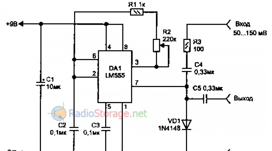
Another circuit for changing the signal spectrum is shown in Figure 2. In it, the audio signal is modulated at a frequency of 50-90 Hz (the frequency is changed by resistor R2) generated by the DA1 chip.

Rice. 2. The second version of the console for creating sound effects.
To avoid strong distortion and degradation of intelligibility, the input signal should not exceed a level of 150 mV and come from a source with a low output impedance, such as an electrodynamic microphone. The output signal is fed to any external amplifier. In this case, in many cases, you can not install capacitors C4-C5 (if there is no constant component in the audio signal).
Voltage-pulse width converter
To create some devices (voltage stabilization or electric motor rotation speed, automatic charger etc.) may require a converter of the control input voltage to the width of the output pulses. A variant of the scheme of such a node is shown in Figure 3; it provides a conversion accuracy of at least 1%.

Rice. 3. Scheme of the voltage-pulse width converter and diagrams explaining the operation.
Chip DA1 has domestic analogue K140UD7 and works as an integrator of the voltage difference Uin and Uon, and on the DA2 timer a single vibrator is assembled with a start from an external clock generator. Resistor R2 is used to set the desired minimum pulse width.
Literature: Radio amateurs: useful schemes, Book 5. Shelestov I.P.
Are available
Buy in bulkThis inexpensive kit is assembled in just 15 minutes and is designed to change the voice. That is, it raises the tone of your voice, turning it into a "cartoon" or vice versa, the tone of your voice can be set very low - male bass. Additional setting will give a metallic color to your voice, and it will become like the voice of a robot. This is the technology of changing the voice in real scale time. This device- a great opportunity for a novice radio amateur to put their theoretical knowledge into practice. It will be interesting and useful for getting acquainted with the basics of electronics and gaining experience in assembling devices. This device is intended for entertainment use only.
Specifications
Principle of operation
The device is assembled on two chips: D1-LM386 and D2-RTS0072B. LM386 is a low frequency amplifier. The RTS0072B is Realtek's custom IC known as the "Voice Changer". This digital microcircuit containing an ADC module, a module digital processing and a DAC module. Depending on the settings of the DIP switch in D2, the spectrum of the input voice signal is shifted or distorted to the “robot voice”.
Device design
Structurally, the device is made on a single-sided printed circuit board made of foil fiberglass with a size of 90x45mm.
Additional Information
DIP switch - designed to set the voice synthesis (change) mode: S1, S2 - a combination of these switches raises or lowers the voice according to the table:
* For example, if a frequency of 1 kHz is applied to the input, the output will be ... S - turns on the voice pitch change mode using only the variable resistor R8. N - disables any voice change. The device works like microphone amplifier. R – turns on the “Robot voice” mode. SW1 – turns on the power supply of the module. Variable resistor R8 - smoothly adjusts the pitch of the voice when SEL is on. Trimmer resistor R4 - adjusts the volume of the "voice mask".
Scheme

Setting
- 1. Connect the +9V DC power supply to the device according to the marking on the printed circuit board. Attention! Incorrect polarity of the power supply can damage the device!
- 2. Lower the SW1 lever of the DIP switch to the down position. You turn on the device.
- 3. By changing the position of the rest of the DIP switches according to the table, try to say something into the microphone. From the loudspeaker you will hear your modified voice.
Questions and answers
- How much does delivery cost within Moscow and the Moscow region?
- You place an order on the site, choose a delivery method from those offered, the shipping cost will be calculated automatically.
- Good day! Bought this product but ran into a problem. Having soldered everything and connected the power, the mask in the mode of changing the pitch of the voice with the help of a variable resistor R8 gives out only a high voice, but when I try to tune it to a lower one, only noise is heard. What could be the problem? Thank you in advance.
- Install a fixed resistor Rh with a nominal value of 10 kOhm in parallel with the extreme terminals of the variable resistor R8.
- Hello, I would like to know about the KT200 kit, does it have a list of elements, and is it available at all?
- Available, please order. The list of components can be seen in the instructions https://cloud.mail.ru/public/4569/5w8xwoc6D
- Make a discount on this product
- Make an order
- Hello. Is the NT200 board available?
- The board is not sold separately.
- Do you have a set of NT200 and a list of elements for it?
- Yes, you can download the list here https://cloud.mail.ru/public/4569/5w8xwoc6D
- Hello, please tell me if there is an instruction in the kit? Is the mask difficult to assemble, since I don’t understand electronics at all
- The set has instructions. If everything is assembled without errors, the device starts working immediately and does not require configuration.
- what is the power of the speaker? If you speak loudly into the microphone, will it not be heard louder than in the speaker?
- Will. Use an amplifier if you need to increase the volume. For example BM2037M https://website/shop/2563690
- How many days will it take to arrive in Vyborg? And if I pay online, will they deliver it to my house or to the post office?
- 3-4 days. It all depends on the shipping method you choose.
- Good afternoon. Is it possible to order already soldered?
- There is no such possibility
- Good evening, I bought a voice mask starter kit from you. what is the best way to install fixed resistors. Thank you.
- Before installing fixed resistors, the value must be monitored with a multimeter.
Project description
IN this project two special effects are created: vibrato and robotic voice. The vibrato effect is generated by changing the frequency of the input signal up and down at 8 Hz. The second effect is created by converting the input voice into a robotic voice. Both effects can be selected depending on whether the input is triggered, ROB or VIB. To shift the frequency level at the output, the microcircuit has seven steps, which are selected using the push buttons SW0, SW1 and SW2 for direct selection electronically, which are connected to the inputs of the ROB, TGD, TGU and VIB microcircuit.
The HT8950 includes an integrated microphone bias amplifier, 8-bit ADC, on-chip SRAM, and an 8-bit current output DAC. 8-bit ADC and DAC provide 8 kHz sampling rate, guaranteeing high quality and high signal-to-noise ratio of the voice output. The IC controls an LED that flashes according to the level of the input voice.
Characteristics:
Input Power - 6VDC @ 300mA
Sound output - Speaker, 8 Ω / 0.5 W
7 steps for shifting the frequency level (Volume control) SW3 (TGU) and SW4 (TGD)
SW2 - Vibrato mode, SW5 - Robot mode
LED to display input voice level
ON/OFF slide switch for power supply
Audio amplifier LM386 with volume presets
PBT (power supply terminal block) connectors for power supply and output speaker connection
Power indicator LED
Size printed circuit board 63mm x 68mm
CN1 – 6V DC power supply input
MIC1 - Electret condenser microphone
LS1 - Speaker
Wiring diagram

PCB (bottom view)


List of radio elements
| Designation | Type | Denomination | Quantity | Note | Shop | My notepad |
|---|---|---|---|---|---|---|
| CN1 | Modulator | HT8950A | 1 | To notepad | ||
| C1 | 4.7uF 63V | 1 | To notepad | |||
| C2, C4, C6, C7, C9, C12 | Capacitor | 0.1uF | 6 | To notepad | ||
| C3, C8 | electrolytic capacitor | 100uF 25V | 2 | To notepad | ||
| C5 | electrolytic capacitor | 10uF/50V or 63V | 1 | To notepad | ||
| C10 | electrolytic capacitor | 22uF/50V | 1 | To notepad | ||
| C11 | Capacitor | 0.22uF | 1 | To notepad | ||
| PR1 | Potentiometer | 200 ohm/250 ohm | 1 | To notepad | ||
| R1 | Resistor | 100 kOhm | 1 | To notepad | ||
| R2 | Resistor | 47 kOhm | 1 | To notepad | ||
| R3, R5 | Resistor | 330 ohm | 2 | To notepad | ||
| R4 | Resistor | 560 ohm | 1 | To notepad | ||
| R6 | Resistor | 33 kOhm | 1 | To notepad | ||
| R7 | Resistor | 2.2 kOhm | 1 | To notepad | ||
| R8, R11 | Resistor | 4.7 kOhm | 2 | To notepad | ||
| R9 | Resistor | 470 ohm | 1 | To notepad | ||
| R10 | Resistor | 2.2 ohm | 1 | To notepad | ||
| SW1 | strip switch | 1 |
The scheme of the prefix for changing the human voice is based on the HT8950A micro-assembly, which converts sound vibrations into two special sound effects - vibrato and "robot voice". The first is created by changing the frequency of the input signal up and down in 8 Hz steps. And the second transforms the audio signal into the voice of the robot. To adjust the output frequency level, there are switches SW0, SW1 and SW2, which are connected to the inputs of the ROB, TGD, TGU and VIB microcircuit. Both effects are selected depending on the triggered input, ROB or VIB.

The HT8950 has a built-in A/C 8-bit A/D converter built into SRAM and an 8-bit D/A converter current output. An 8 kHz sample rate converter guarantees an acceptable level of quality and a high signal-to-noise ratio of the output voice. The red LED blinks depending on the voice input level.

Specifications prefixes
Input - 6V 300mA direct current
Output - speaker, 8 ohm 0.5 W
7 effect levels
SW2 - Vibrato mode, SW5 - robot voice
LED indicator for level display
ON/OFF power switch
Audio amplifier on LM386 with volume control
Power LED
PCB dimensions 63 x 68 mm

The prefix can be used to mask your voice during New Year's jokes on the phone or Skype, as well as in various children's toys. A part list and a list of used radio components are attached.
