Satellite antenna. Parabolic antenna Parabolic transmitting antennas
Read also
The operation of satellite antennas, in particular those that receive television signals, is based on the optical property of a parabola. A parabola is the locus of points equidistant from a line (called the directrix) and from a point not on the directrix (called the focus). From the above definition of a parabola it is not difficult to get the “school” definition: a parabola is the graph of a quadratic function y=ax^2+bx+c (in particular, y=x^2).

Let us formulate the mentioned optical property of a parabola. If you place a point source of light (a light bulb) at the focus of a parabola and turn it on, then the rays, reflected from the parabola, will go parallel to the axis of symmetry of the parabola, and the leading front will be perpendicular to the axis.

The opposite is also true - if a stream of rays parallel to the axis of symmetry falls on a parabola, then, having reflected from the parabola, the rays will come to focus, and simultaneously, if the leading front of the stream of rays is perpendicular to the axis.

When a parabola rotates around its axis of symmetry, a paraboloid of revolution is obtained - a second-order surface. For any section of a paraboloid by planes passing through the axis of symmetry, equal parabolas with a common focus are obtained, therefore the paraboloid also has an optical property. If you place the emitter at the focus, the rays, reflected from the surface, will go parallel to the axis of rotation. And if rays parallel to its axis fall on a paraboloid, then after reflection they all converge at the focus.

Optical property is the fundamental basis of parabolic antennas. Antennas can rotate, for example, parabolic antennas at airports, shaped like “slices” of huge paraboloids, they both transmit and receive signals. Antennas may be stationary. The last type includes household satellite TV antennas(“dishes”): they are aimed at a relay satellite located high above the Earth in geostationary orbit, after which their position is recorded.
Since the satellite is far from the surface, the rays coming from it at the point of reception by the antenna can be considered parallel. At the focal point of the satellite dish is a receiver, from which the signal is sent via cable to the TV.

The same idea is used to create spotlights for railway locomotives, car headlights, and can even be used for cooking food in the field. The optical property of a parabola “knows” the world of living nature. For example, some northern flowers, living in conditions of short summer and lack of sunlight, open their petals in the shape of a paraboloid to make the “heart” of the flower warmer. “Parabolic” are such alpine and arctic flowers as alpine lumbago, glacial bekwichia, polar poppy. Thanks to the optical property of a parabola, the ripening of seeds in such flowers is accelerated. Another consequence of their parabolic properties that is beneficial for flowers is the attraction of insects that like to “soak up” in the flower bowl, and this affects the process of pollen transfer (pollination).
A parabolic antenna consists of a feeder and a reflector in the form of a paraboloid of rotation or part thereof.

When you can use the optical representation of the ray path. The design of the feed is such that it emits waves whose front shape is close to spherical. The parabolic reflector converts the spherical front into a flat one, which determines a narrow pattern.
There are two types of antennas: axisymmetric and axisymmetric.
The back reaction of the reflector to the feed can be reduced by moving the feed away from the field of the reflected wave.
The equation of a parabola in the polar coordinate system is determined by the equality
![]() ,
,
where: – focal length, – opening angle.
If the opening angle is , the antenna is called long-focus, otherwise - short-focus. DN width:
![]() .
.
The directional properties of antennas are deteriorated due to phase distortions of the field in the aperture, which can be caused by a deviation of the reflector profile. The permissible deviation of the field phase in the aperture is considered to be
 Then the manufacturing error of the reflector profile is equal to
![]() .
.
The greatest accuracy should be in the center at
In cases where a high protective effect is not required, to reduce weight and wind load, the surface of the reflectors is perforated or made of lattice. The ratio of the energy passed through the reflector to the incident energy is called the transmission coefficient T 0.
For perforated surfaces:
 ,
,
where S is the area of the reflecting surface; S¢ is the total area of all holes in the reflector; r is the radius of the holes.
The diameter of the holes should not exceed the distance between the centers of the holes ![]() .
.
 The figure shows the dependence of the transmission coefficient on the ratios and for a grating reflector made of rectangular plates with dimensions d And t and the distance between the plates and for a grating reflector made of parallel wires with a radius r.
a) from rectangular wires, b) from round wires
The advantage of a parabolic antenna is its relative simplicity and low cost. Disadvantages - low efficiency factor = 30 - 48 dB (), difficulty in matching with the feeder.
To improve directional properties and increase the SCR to 55 - 70 dB, cylindrical screens (hoods) are used.
When using waves with orthogonal polarization, the feed horn must have a square cross-section. The natural noise immunity of axisymmetric antennas in the shadow region is low - the radiation level in the Poisson lobe region is only 5-10 dB lower than the isotropic radiation level. In this regard, the problem of improving noise immunity in the rear half-space is very important. It is especially acute for radio relay communications, where for normal operation of the line it is necessary to ensure in the entire shadow region a radiation level 20-30 dB below isotropic.
Methods developed to date for reducing shadow radiation come down to reducing the excitation level of the antenna edge and the diffraction ability of the edge, additional shading of the diffraction field, compensation of edge fields, and dephasing of edge fields.
The level of the field exciting the edge can be reduced either by creating special distributions in the aperture, or by applying absorbing materials to the working surface of the mirror, and in both cases the antenna gain is reduced. Coating the inner surface of a cylindrical hood with an absorber is quite effective. In this case, the field level from the antenna at the edge of the hood is significantly weakened

With a sufficiently extended hood, it is thus possible to provide wide-range suppression of shadow radiation by 10-15 dB without a noticeable decrease in the efficiency of the antenna.
Reducing the diffraction ability of an edge can be achieved in many ways. These are, for example, quarter-wave traps or impedance devices. Such devices are difficult to manufacture and do not completely solve the problem. Good results can be achieved by covering the outer surface of the antenna with an absorber. So, according to the data, this allows you to reduce the field level in the shadow area by 7-10 dB.
In some cases, it is advisable to use rounded edges. Suppression is effective if , where is the radius of the rounding (Fig.).
Diffraction radiation from the edge can be significantly reduced if the transition from metal to free space is made smooth, that is, the peripheral region of the antenna is made translucent.
Effective attenuation of the diffraction field of an edge can be achieved using disk metal screens(rice.).
If the screen profile is made parabolic with a focus on the edge of the antenna (see figure), then the field reflected from it will be concentrated in the vicinity of the main lobe of the antenna and its influence will be completely unnoticeable.
Compensation of the diffraction fields of the edge can be carried out using a slit screen (see figure); at certain sizes, its diffraction fields on edges A, B, C compensate each other in the direction.
It is effective to use a slot screen together with a solid disk screen (see figure).
Let's begin our consideration of devices for suppressing shadow radiation by dephasing the diffraction fields of the edge with the so-called beveled hoods (see figure). The radiation pattern in the NN plane is usually horizontal; in this case, the bevel of the hood AB lies in the vertical plane) an antenna with a beveled hood can be determined
in the following way. If we denote the angle between the NN plane and the polarization of the feed field (axis OY), then for the field of the main polarization in the back half-space we obtain.
where 2 R- phase difference of signals diffracted in the direction from the upper and lower points of the hood.
Intensive suppression of radiation in a given plane can be carried out using a screen (or flange) consisting of two half-disks (see Fig.), the dimensions of which are selected in such a way that the diffraction fields from the upper half-disk are shifted in phase by n relative to the fields from lower half-disc ![]() . In the plane of separation
. In the plane of separation
Of particular interest are devices with smooth dephasing of diffraction fields at the edge. In particular, if the edge is cut in a spiral (see figure), then the phase of the fields in the direction changes according to the law.
Much top scores can be obtained by making the screen in the form of a polygonal star (see figure).
DOUBLE-MIRROR CASSEGRAIN ANTENNA (ADG)
In 1672, the French optician Cassegrain invented a telescope consisting of 2 mirrors. The focus is the real focal point and is located near the primary mirror. The second focus is the virtual focal point and is located at the focus of the paraboloid. An antenna built according to this design makes it possible to shorten the microwave path and place the main part of the feed structure behind the mirror.
Reducing the focal length of the main mirror, as well as the small scattering of the feed field into the rear hemisphere, helps to reduce the noise temperature.
In simple DZA, a hyperbolic mirror is used as an intermediate mirror. Such an antenna is called a two-mirror antenna with a hyperbolic small mirror ADH. A hyperbolic mirror has two foci. The antenna is made so that F1 coincides with the focus of the parabolic reflector, and F2 with the focus of the feed. ADH has a higher CPC value and better coordination with the feeder. Depending on the ratio of diameters, the CIP is 0.5..0.6. Usually taken.

Geometry of the classical Cassegrain antenna
In a two-mirror antenna, it is possible to obtain a better amplitude distribution of the field in the opening of a large parabolic mirror with a sharp drop in the field at its edges by installing a special flange 3 on the small mirror. This achieves a reduction in the intensity of the side lobes of the antenna's radiation pattern and improves its protective effect. All of the indicated properties of a two-mirror antenna are essential for the operation of space communication lines, therefore these antennas are often used in space complexes.

Two-mirror antenna
The disadvantages of a two-mirror antenna are the presence of a reverse reaction of the small hyperbolic reflector to the feed and shading of the antenna opening by the small mirror. Shading of the aperture causes an increase in the intensity of the side lobes in the antenna radiation pattern.
Ministry of Education and Science of the Russian Federation
Tomsk State University of Control Systems and Radioelectronics
Department of Microwave and Quantum Radio Engineering
(microwave and radio frequency)
Laboratory work for the course “Antennas”
"Study of parabolic antenna patterns"
Checked: Complied with Article 121-2:
Fateev A.V.______ Yakushenko Yu.V._______
Ermolova M.I._______
Kalugin P.S.________
Introduction
The purpose of this work is: measuring the radiation pattern of a parabolic antenna in the far zone, measuring the radiation pattern of a parabolic antenna in the near zone for the feed removed from the focus of the mirror, measuring the polarization diagram of the antenna.
1 Description of the experimental setup
The block diagram of the installation is shown in Figure 1.1.
1 – P2M block; 2 – transmitting horn antenna; 3 – receiving parabolic antenna; 4 – detector; 5 – P2M block
Figure 1.1 – Structural scheme experimental setup.
2 Basic calculation formulas
The pattern of a parabolic antenna is calculated by the formula:
where is the Bessel function;
– wave number, – wavelength;
cm– radius of the mirror;
– the angle between the normal to the opening and the direction to the point in space where the field is determined.
The wavelength is calculated using the formula:
λ =4 cm;
We calculate the distance to the far zone using the formula:
D– paraboloid diameter, – wavelength.
To measure the radiation pattern in the near zone, we install a parabolic antenna from the transmitting antenna at a distance, which is calculated by the formula:
where is the distance between the transmitting and receiving antennas;
– the amount of offset of the phase center of the feed;
-focal length;
– mirror diameter.
3 Results of work and their analysis
Let's use formula (2.2) and (2.3) and determine the minimum radius of the far zone.
Using formula (2.4) we calculate R wholesale :
![]()
Let's use formula (2.1), construct the pattern of the parabolic antenna and determine the width of the radiation pattern at a level of 0.5 from the maximum value. The pattern of a parabolic antenna is shown in Fig. 3.1.

Figure 3.1 – Parabolic antenna pattern
The beam width is 7.68 degrees.
The radiation patterns obtained experimentally for the vertical and horizontal polarization of the transmitting antenna are presented in Figures 3.2 and 3.3, respectively. The focus of the mirror is aligned with the phase center of the feed ( f=22cm). Distance between antennas 8 m. For vertical polarization of the antenna, the width of the pattern is 5.5 degrees, and for horizontal polarization it is 10 degrees.

Figure 3.2 – Pattern for vertical polarization

Figure 3.3 – Pattern for horizontal polarization
Let us shift the irradiator from the focus along the mirror axis by a distance = 3 cm and remove the pattern of the parabolic antenna in the far zone with vertical polarization of the feed, the resulting pattern is presented in Figure 3.4.

Figure 3.4 – Pattern for vertical polarization of a parabolic antenna with a shifted focus
Align the phase center of the feed with the focus of the mirror and rotate the feed at an angle of 6° from the mirror axis. The resulting pattern for vertical polarization is presented in Figure 3.5. The width of the pattern is 10 degrees.

Figure 3.5 – Pattern for vertical polarization with an angle of deflection of the feed by 6 degrees
Let's place the feed of the parabolic antenna into focus and, by rotating the transmitting horn antenna, remove the polarization diagram of the parabolic antenna. We carry out measurements at 20° intervals; the resulting polarization diagram is presented in Figure 3.6.

Figure 3.6 – Polarization diagram
Let's install the transmitting horn antenna at a distance = 2 m And Let's remove the pattern of the parabolic antenna for vertical polarization with the feed being in focus. The resulting pattern is presented in Figure 3.7. The width of the pattern is 9 degrees.

Figure 3.7 – Pattern for vertical polarization at R wholesale =2 m
Let us shift the feed of the parabolic antenna from the focus to a distance = 3 cm and remove the DN. In this case, the transmitting antenna must be at a distance. The resulting pattern with vertical polarization is presented in Figure 3.8. The width of the radiation pattern is 8 degrees.

Figure 3.8 – Pattern for vertical polarization with shifted focus

Figure 3.9 – Pattern for vertical polarization with an unbiased focus in the far zone
Conclusion
During laboratory work The directivity patterns of the parabolic antenna in the near and far zones, as well as the polarization pattern, were measured.
Analyzing the results obtained, we can conclude that when the irradiator is deflected by a certain angle, the maximum of the diagram shifts towards the deflection of the irradiator. When the irradiator is moved out of focus, the width of the pattern narrows.
When the feed source is displaced from the focus along the mirror axis, phase distortions appear on the surface of the aperture, symmetrical relative to the top of the mirror, which expands the main lobe of the radiation pattern; to compensate for phase errors in the aperture, we move the feed source out of focus in the near zone; the radiation pattern is the same as if the feed would be in focus, and the receiving antenna would be in the far zone.
Or-bi-ta satellite no-sits the name of geo-sta-tsi-o-nar-noy, if during the rotation of the Earth the satellite always vi- sits over the same point on the earth's surface. Such or-bi-you are often used in communication systems and po-zi-o-ni-ro-va-niya.
The satellite you see in the picture is a symbol of the space program of our country -us. This is SOYUZ-TM.
And so at some point you looked at the program “Time” - the main in-for-ma-tsi-on- No tele-pro-gram-we countries.
Well, in the cartoon we see how the process of re-re-da-chi sig-na-la proceeds, for example, in modern times -th satellite-in-the-television.
Let's talk straight and call it di-rek-tri-soy. Let's take a point outside of it. Geo-met-ri-che-skoe place-one-hundred-to-checks, equally-distant from di-ri-rivers-three-sy and a given point (fo-ku-sa), on- zy-va-et-sya pa-ra-bo-loy.
If you point the rays of light at the pa-ra-bo-lu, parallel to its axes of sym-metry, then all the rays come together in fo-ku-se pa-ra-bo-ly. This property is called the op-ti-che-skim property of pa-ra-bo-ly.
The reverse is also true. If you place the lamp in the focus, then the rays, having developed from the pa-ra-bo-ly, will go para-lel-but, what does the border of light have to do with it?
If you rotate the pa-ra-bo-lu from its axis of symmetry, then you get a rotating surface niya second in a row - pa-ra-bo-lo-id. Since in any given plane co-containing the axis of symmetry, one and the same parameter is obtained bo-la, then the op-ti-che-st property is also true for pa-ra-bo-lo-i-da. If you place the lamp in the focus of pa-ra-bo-lo-i-da, then the rays, radiating from the top, let's go together. The opposite is also true.
It is precisely this property that is used in satellite an-ten-nahs. Since the satellite is located very far from the antenna, the rays can be considered almost parallel to us, and when -em-nick sign-na-la sta-vit-sya in fo-kus pa-ra-bo-lo-i-da.
Additional Information:
On la-you-ni focus means "hearth, fire". Like the ma-te-ma-ti-che-che-term the word “fo-kus”
Reception of satellite television signals is carried out by special receiving devices, an integral part of which is an antenna. For professional and amateur reception of satellite transmissions, parabolic antennas are the most popular, due to the property of a paraboloid of rotation to reflect rays parallel to its axis falling on its aperture to one point, called the focus. An aperture is a part of the plane limited by the edge of a paraboloid of revolution.
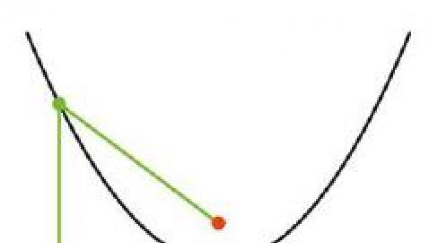
A paraboloid of revolution, which is used as an antenna reflector, is formed by rotating a flat parabola around its axis. A parabola is the locus of points equidistant from given point(focus) and a given straight line (directrix) (Fig. 6.1). Point F is the focus and line AB is the director. Point M with coordinates x, y is one of the points of the parabola. The distance between the focus and the directrix is called the parameter of the parabola and is denoted by the letter p. Then the coordinates of the focus F are as follows: (p/2, 0). The origin (point 0) is called the vertex of the parabola.
By definition of a parabola, the segments MF and PM are equal. According to the Pythagorean theorem MF^2 =FK^2+ MK^2. At the same time, FK = = x - p/2, KM = y and РМ = x + p/2, then (x - p/2)^2 + y^2 = (x + p/2)^2.
By squaring the expressions in brackets and bringing similar terms, we finally obtain the canonical equation of the parabola:
y^2 = 2px, or y = (2px)^0.5. (6.1)
Millions of antennas have been made to receive signals using this classic formula. satellite television. Why did this antenna deserve attention?
Parallel to the axes of the paraboloid, rays (radio waves) from the satellite reflected from the aperture to the focus travel the same (focal distance). Conventionally, two rays (1 and 2) fall on the opening area of the paraboloid in different points(Fig. 6.2). However, the reflected signals of both beams travel the same distance to the focus F. This means that the distance A+B=C+D. Thus, all the rays that are emitted by the satellite’s transmitting antenna and to which the parabolic mirror is directed

loid, concentrate in phase at focus F. This fact is proven mathematically (Fig. 6.3).
The choice of parabola parameter determines the depth of the paraboloid, i.e. the distance between the vertex and the focus. With the same aperture diameter, short-focus paraboloids have a large depth, which makes it extremely inconvenient to install the feed at the focus. In addition, in short-focus paraboloids, the distance from the feed to the top of the mirror is much less than to its edges, which leads to uneven amplitudes at the feed for waves reflected from the edge of the paraboloid and from the zone close to the top.
Long-focus paraboloids have a shallower depth, the installation of the feed is more convenient and the amplitude distribution becomes more uniform. So, with an aperture diameter of 1.2 m and a parameter of 200 mm, the depth of the paraboloid is 900 mm, and with a parameter of 750 mm it is only 240 mm. If the parameter exceeds the radius of the aperture, the focus in which the irradiator should be located is located outside the volume limited by the paraboloid and the aperture. The optimal option is when the parameter is slightly larger than the aperture radius.
Satellite antenna- the only amplifying element of the receiving system that does not introduce its own noise and does not degrade the signal, and therefore the image. Antennas with a mirror in the form of a paraboloid of rotation are divided into two main classes: symmetrical parabolic reflector and asymmetrical (Fig. 6.4, 6.5). The first type of antennas is usually called direct-focus, the second - offset.


An offset antenna is like a cut out segment of a parabola. The focus of such a segment is located below the geometric center of the antenna. This eliminates the shading of the useful area of the antenna by the feed and its supports, which increases its efficiency with the same mirror area as an axisymmetric antenna. In addition, the feed is installed below the center of gravity of the antenna, thereby increasing its stability in wind conditions.
It is this antenna design that is most common in individual satellite television reception, although other principles for constructing terrestrial satellite antennas are currently used.
It is advisable to use offset antennas if an antenna size of up to 1.5 m is required for stable reception of programs from the selected satellite, since as the total area of the antenna increases, the effect of mirror shading becomes less significant.
The offset antenna is mounted almost vertically. Depending on the geographic latitude, its inclination angle is slightly

is changing. This position prevents precipitation from collecting in the antenna bowl, which greatly affects the quality of reception.
The operating principle (focusing) of direct-focus (axisymmetric) and offset (asymmetric) antennas is shown in Fig. 6.6.
For antennas, directional characteristics are of particular importance. Thanks to the ability to use antennas with high spatial selectivity, satellite television reception is possible. The most important characteristics of antennas are gain and radiation pattern.
The gain of a parabolic antenna depends on the diameter of the paraboloid: the larger the diameter of the mirror, the higher the gain.
The dependence of the gain of a parabolic antenna on the diameter is shown below.
The role of the gain of a parabolic antenna can be analyzed using light bulb(Fig. 6.7, a). The light is evenly scattered into the surrounding space, and the observer’s eye perceives a certain level of illumination corresponding to the power of the light bulb.

However, if a light source is placed at the focus of a paraboloid with a gain of 300 times (Fig. 6.7, b), its rays, after reflection by the surface of the paraboloid, will be parallel to its axis, and the color strength will be equivalent to a source with a power of 13,500 W. The observer's eyes cannot perceive such illumination. The principle of operation of the spotlight is, in particular, based on this property.
Thus, an antenna paraboloid, strictly speaking, is not an antenna in the sense of converting the electromagnetic field strength into a signal voltage. A paraboloid is just a reflector of radio waves, concentrating them at a focus, where the active antenna (feeder) should be placed.
The antenna radiation pattern (Fig. 6.8) characterizes the dependence of the amplitude of the electric field strength E created at a certain point on the direction to this point. In this case, the distance from the antenna to this point remains constant.
An increase in the antenna gain entails a narrowing of the main lobe of the radiation pattern, and narrowing it to a value of less than 1° leads to the need to equip the antenna with a tracking system, since geostationary satellites oscillate around their stationary position in orbit. Increasing the width of the radiation pattern leads to a decrease in the gain, and therefore to a decrease in the signal power at the receiver input. Based on this, the optimal width of the main lobe of the radiation pattern is

The width is 1...2°, provided that the satellite's transmitting antenna is kept in orbit with an accuracy of ±0.1°.
The presence of side lobes in the radiation pattern also reduces the antenna gain and increases the possibility of receiving interference. In many ways, the width and configuration of the radiation pattern depend on the shape and diameter of the receiving antenna mirror.
Most important characteristic parabolic antenna is the precision of the shape. It should repeat the shape of a paraboloid of revolution with minimal errors. The accuracy of the shape determines the antenna gain and its radiation pattern.
It is almost impossible to make an antenna with the surface of an ideal paraboloid. Any deviation from the actual shape of the parabolic mirror from the ideal shape affects the performance of the antenna. Phase errors occur, which degrade the quality of the received image, and the antenna gain decreases. Distortion of the shape also occurs during the operation of antennas: under the influence of wind and precipitation; gravity; as a consequence of uneven heating of the surface by the sun's rays. Taking these factors into account, the permissible total deviation of the antenna profile is determined.
The quality of the material also affects the antenna's performance. For the manufacture of satellite antennas, steel and duralumin are mainly used.
Steel antennas are cheaper than aluminum ones, but are heavier and more susceptible to corrosion, so anti-corrosion treatment is especially important for them. The fact is that a very thin near-surface layer of metal is involved in the reflection of the electromagnetic signal from the surface. If it is damaged by rust, the effectiveness of the antenna is significantly reduced. It is better to first coat a steel antenna with a thin protective layer of some non-ferrous metal (for example, zinc) and then paint it.
These problems do not arise with aluminum antennas. However, they are somewhat more expensive. The industry also produces plastic antennas. Their mirrors with a thin metal coating are subject to distortion of shape due to various external influences: temperature, wind loads and a number of other factors. There are mesh antennas that are resistant to wind loads. They have good weight characteristics, but have performed poorly when receiving Ki-band signals. It is advisable to use such antennas for receiving C-band signals.
At first glance, a parabolic antenna seems like a rough piece of metal, but nevertheless it requires careful handling during storage, transportation and installation. Any distortion in the shape of the antenna leads to a sharp decrease in its efficiency and deterioration in the quality of the image on the TV screen. When purchasing an antenna, you need to pay attention to the presence of distortions on the working surface of the antenna. Sometimes it happens that when anti-corrosion and decorative coatings are applied to the antenna mirror, it is “guided” and takes on the shape of a propeller. You can check this by placing the antenna on a flat floor: the edges of the antenna should touch the surface everywhere.