Push-pull unch on 6p45s lamps, Manakov circuit. Single-ended tube amplifier
Read also
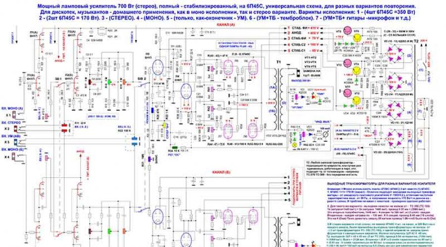
— I present a device with integrated into one body preamp and an audio power amplifier with perfect sound quality. The lamp has stabilized modes, and in stereo it produces an output power of 350 W per channel. In mono mode, if four 6p45S lamps are installed in the final stage, it will be 700 W. The maximum power shown here was measured before the clipping appeared on the sine wave signal.

The picture is clickable. You can take the diagram on a large scale → Here
Natural musical power will be slightly less. If two lamps are installed in the output path, then naturally the power will be halved. When assembling a tube sound amplifier, no special selection of lamps is required, since each 6P45S tetrode has an adjustment function. Therefore, everything is simple - take the diagram and start doing it.
Amplifier based on 6P45S tubes
A tube amplifier assembled according to this circuit using 6P45S tetrodes has been tested many times and works great. Two devices were manufactured in a stereo version; if we consider them as mono, then we get four devices. This universal circuit makes it possible, without changing anything in it, to assemble the simplest lamp, such as, for example, a terminal amplifier and work with a remote control. Or you can make more complex designs, for example: with a built-in tone block, or even more advanced - install additional input modules for connecting electric guitars, microphones or synthesizers.
Tube audio amplifier circuit, also allows you to make the amplifier both monophonic and stereo. In addition, it is possible to install almost any radio amplification tubes without making changes to the circuit. For example: instead of one 6P45S, you can use 2 pieces without any problems. 6P36S or 6P44S. Based on this, it is easy to calculate: if the output stage is mounted on four 6P36S lamps, this will be equivalent in power to two 6P45S.
Output transformer
Also, the output transformer will work stably with a final stage consisting of both two 6P45S and four 6P36S lamps. The output trans from the Soviet radio broadcast amplifier U-100U4.2, which has an ideal frequency and excellent quality, performed well. If you find such a transformer, it will solve your labor-intensive problem - you won’t need to wind the output from scratch. In addition to this, the sound power was within 175 W.
In this design, some components recommended by famous radio amateurs were used. In particular, presented here tube audio amplifier circuit contains such output transformers. But you can install those that you have in stock and that are suitable in terms of parameters, everything will work perfectly.
Voltage regulator
A characteristic feature of this modification of the amplifier is the use of the stabilizing mode function. The use of such stabilization eliminates the possibility of a negative impact on the device due to strong differences mains voltage. Also given tube amplifier sound is not sensitive to voltage surges in the power circuit, during which all modes of radio tubes operate intermittently.
At the stage of assembling the structure, the device was tested with and without mode stabilization installed - a huge difference between the two options was revealed. The device with a stabilizer was much superior to the second option in terms of reliability and stability in operation, purity of the sound picture, etc. You shouldn't skimp on a pair of transistors. Therefore, the best solution would be for you if you additionally assemble voltage stabilizers. As a result, you will be rewarded with high-quality amplifier performance and excellent sound.
Installing stabilizer transistors
For ease of installation of transistors in stabilizer circuits, you need to use transistors in a plastic case, which are easiest to attach directly to the amplifier body. Thereby providing good thermal stability to transistors. In this circuit I used transistors from the horizontal scan and power supply of branded TVs.
The constant supply voltage in the preliminary stage, supplied to the filament circuit of all lamps installed there, coped perfectly with all kinds of background distortion and noise. It's actually not audible at all. Naturally, I distributed the grounding points, which are laid from one cascade to another. And the last point is output to the common housing at the cathode of the output tetrodes, and the power wire also converges at this point high voltage by "minus". Pay special attention to correct installation.
The use of the SRPP circuit (in the Russian sense - a cascade with a dynamic load) in pre-amplifier stages is completely justified by its resistance to overloads, excellent quality, low output resistance.
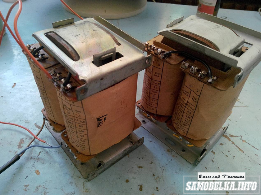
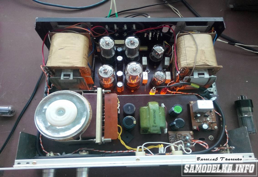
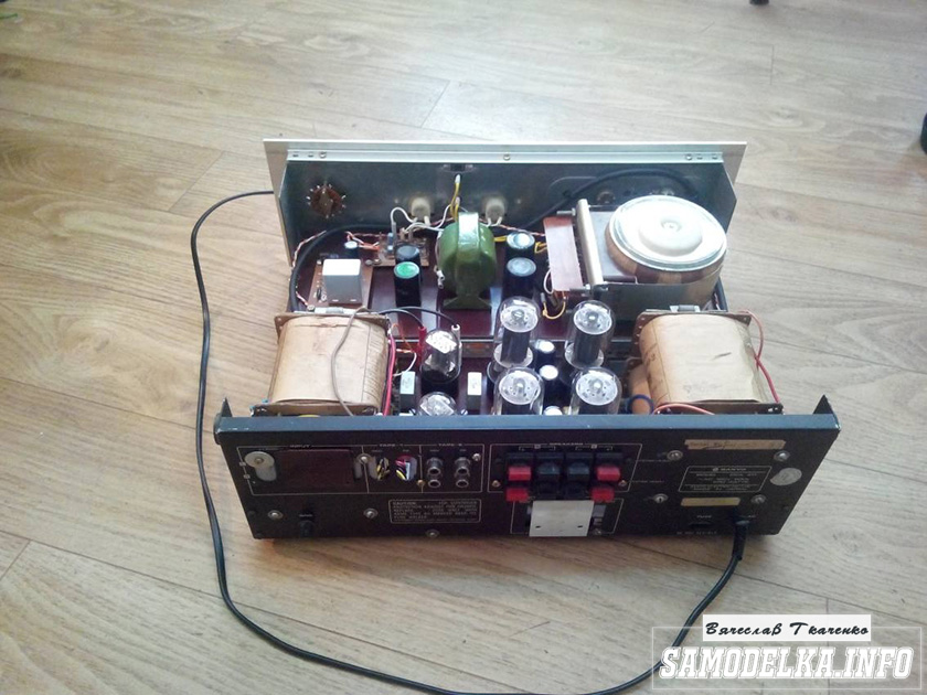
The presented photos show ready-made complete tube amplifiers: The first is a complete stereo amplifier with a power of 700 W; the second - power 300 W.

This was developed somewhere in the late 80s. During this time it has shown itself to be worthy and versatile: suitable for amateurs high-quality sound(composed for himself), and for musicians who need power.
Brief lyrical introduction. At one time, the amplifier published in the magazine "Radio" in 1972 was very popular. I also repeated this pattern. Its disadvantages are known to many who repeated it: low linearity, poor stability at low frequency, insufficient stability at high frequency (which is why a corrective air conditioner was introduced into the circuit), narrow frequency range, and something else that I don’t remember now. And most importantly, the sound left much to be desired.
I couldn’t stand this at home: my ears are not official :) The first thing I started the modernization with was replacing the output trance. The changes made to the output trance suggested themselves - tighten the connection of the windings feedback(ultralinear) with the remaining windings, which reduces Kg by higher frequencies, and improve the frequency and phase characteristics of the output stage. In the version that I used in the new design, it was possible to expand the frequency range, increase HF stability, and lower the output impedance. The sound has noticeably improved, but now the entire circuit design (a clone of the so-called “Williamson circuit”) began to seem far-fetched in Hi-Fi - it was done somehow “head-on”, the weak link remained weak stability with OOS at infra-low frequencies, increased nonlinear and frequency distortions (especially at HF).
Further improvement resulted in the complete abandonment of this scheme. Many different circuit solutions were tried. Attempts to find the best option led to the solution that I propose. At the input, I used a cascode UA with high linearity, then a phase-inverted cascade with a divided load, which has the highest linearity. At the same time, I connected them directly to reduce phase shifts along the signal path. At the output, however, the familiar ultra-linear output stage remained with minor changes (for the purpose of ease of setup and increased stability), and, as already mentioned, with an improved output trance. In the diagram, I conventionally divided the preliminary stages, a bunch of triodes in which is actually my know-how ;), and the output stage, instead of which you can connect any suitable one. With a properly manufactured and adjusted amplifier, the maximum amplitudes on the control grids of the output lamps should be at least 80V at a load of 47k. And this made it possible to fully pump up the 6P45S. And what is important, with all its advantages, the scheme turned out to be even easier than that, from which I had to leave.
The result is an amplifier with a sound that (with proper measures) can easily qualify for hi-end ;) The amplifier is absolutely stable, so it can be used both with deep OOS and without it at all - the linearity of all stages ensures low distortion and open loop OOS.
From two 6P3S, I managed to get >150 watts, from two 6P45S - >220 ;), and in the version with grid currents (especially for musicians) - 400 watts of peak power! But that diagram is already noticeably different from the one given.
I can’t give detailed parameters of the amplifier now - I haven’t measured it for a long time. For those who need sound and not parameters, I have given enough information for repetition, and if it is really necessary, I can (albeit at great cost) re-measure them. I would probably try it on for a magazine. And here it will do :o)
As for setup, it is simple:
- assemble a standard parameter measurement scheme;
- disable OOS;
- turn on the power and warm up the cathodes;
- resistors R10 and R11 set the quiescent currents of the output. lamps 30...60mA (0.06...0.12V at the cathodes), but always identical;
- without supplying a signal to the input, use the R2 regulator to set the cathode of the bass reflex to 105V;
- apply a signal to the input until the load voltage reaches 15 volts (for a 6-ohm variant);
- resistor R9 sets the minimum of the 2nd harmonic at the output;
- restore OOS (optional).
Point 7 can be skipped if you replace R8 and R9 with one with a resistance of 12k (this may not even affect the quality in any way, especially with OOS).
To power the amplifier, additional voltages were needed: 410V (10mA/channel) and stabilized 68V (b/t). The diagram shows one of the available options for obtaining them. Here you can do it in different ways. For example, I have a stub source. +220V to power the preamplifier, so I got +68 as a divider.
At one time, the scheme was shrouded in trade secrets :). Now please - let anyone who wants to try it. I repeat that the UN-FI combination is universal and can be used to drive various PP output stages (triode, pentode, class A, AB). For each specific case, you may have to recalculate some elements, which is done very easily. This is how I can help those in need.
P.S: Priboy amplifiers lend themselves well to such modifications - the quality improves noticeably.
List of radioelements
| Designation | Type | Denomination | Quantity | Note | Shop | My notepad |
|---|---|---|---|---|---|---|
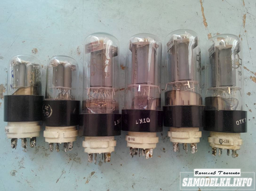
| Radio lamp | 6N1P | 2 | To notepad | |||
| Radio lamp | 6P45S | 2 | To notepad | |||
| C1, C5, C6 | Capacitor | 1 µF | 3 | To notepad | ||
| C2 | Electrolytic capacitor | 47 µF | 1 | To notepad | ||
| C3 | Capacitor | 0.1 µF | 1 | To notepad | ||
| C4 | Capacitor | 0.047 µF | 1 | To notepad | ||
| R1 | Resistor | 220 kOhm | 1 | 0.5 W | To notepad | |
| R2, R9 | Trimmer resistor. | 4.7 kOhm | 2 | To notepad | ||
| R3 | Resistor | 100 Ohm | 1 | 0.5 W | To notepad | |
| R3 | Resistor | 100 kOhm | 1 | 2 W. By mistake in the circuit two resistors are named as R3 | To notepad | |
| R4 | Resistor | 2 MOhm | 1 | 0.5 W | To notepad | |
| R6 | Resistor | 1 MOhm | 1 | 0.5 W | To notepad | |
| R7 | Resistor | 12 kOhm | 1 | 2 W | To notepad | |
| R8 | Resistor | 10 kOhm | 1 | 0.5 W | To notepad | |
| R10, R11 | Trimmer resistor | 22 kOhm | 2 | To notepad | ||
| R12, R13 | Resistor | 47 kOhm | 2 | 0.5 W | To notepad | |
| R14, R15 | Resistor | 1 kOhm | 2 | 0.5 W | To notepad | |
| R16, R17 | Resistor | 22 kOhm | 2 | 1 W | To notepad | |
| R18, R19 | Resistor | 2 ohm | 2 | 2 W | To notepad | |
| R20 | Resistor | 2.7 kOhm | 1 | 1 W | To notepad | |
| R21, R22 | Resistor | 68 ohm | 2 | 2 W | To notepad | |
| Discharger | 1 |
Today we have a useful homemade product for connoisseurs good sound: high quality DIY tube amplifier
Hello!
I decided to assemble a push-pull tube amplifier (my hands were really itching) from the parts I had accumulated over a long time: housing, lamps, sockets for them, transformers, etc.
I must say that I got all this stuff for free (you mean free of charge) and the cost of my new project will be 0.00 hryvnia, and if I need to buy something in addition, I’ll buy it for rubles (since I started my project in Ukraine, and I’ll finish already in Russia).
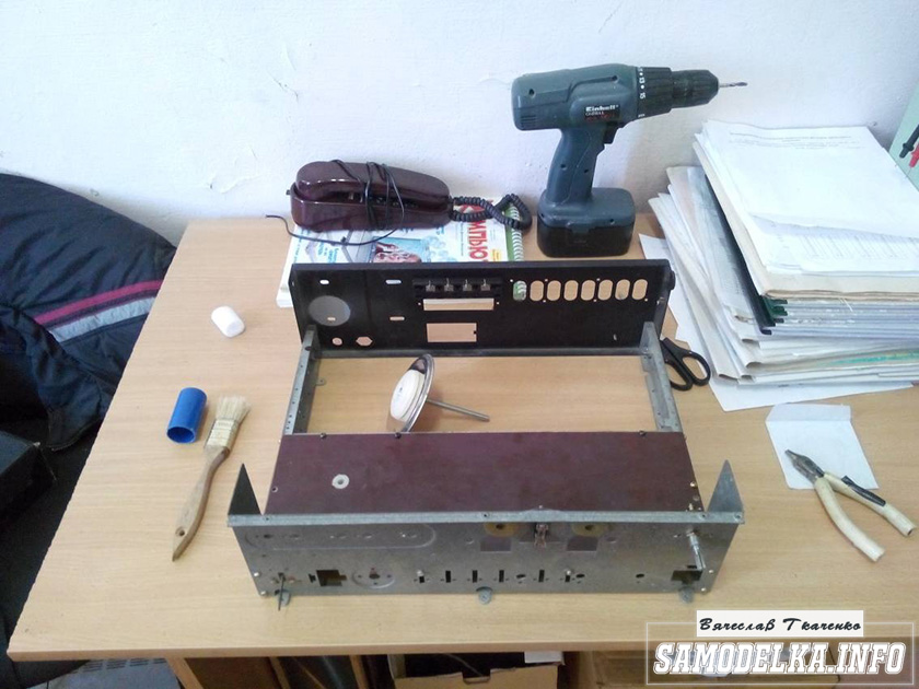
I'll start the description with the body.

Once upon a time it was, apparently, a good amplifier from SANYO model DCA 411.
But I didn’t have a chance to listen to it because I got it in a terribly dirty and non-working state, it was dug up beyond repair and the burnt 110 V power supply (Japanese, probably) smoked all the insides. Instead of the original final stage microcircuits, there are some snot from Soviet transistors (this is a photo from the Internet of a good example). In short, I gutted it all out and began to think. So, I couldn’t think of anything better than stuffing a lamp there (there’s quite a lot of space there).
Decision is made. Now we need to decide on the scheme and details. I have a sufficient number of 6p3s and 6n9s lamps.

Due to the fact that I had already assembled a single-cycle amplifier for 6p3s, I wanted more power and, having rummaged through the Internet, I chose this push-pull amplifier circuit for 6p3s.
Circuit of a homemade tube amplifier (ULF)
The diagram is taken from the website heavil.ru
I must say that the scheme is probably not the best, but due to its relative simplicity and availability of parts, I decided to stick with it. Output transformer (an important figure in the plot).
It was decided to use the “legendary” TS-180 as output transformers. Don’t throw stones right away (save them for the end of the article :)) I myself have deep doubts about this decision, but given my desire not to spend a penny on this project, I will continue.
I connected the trance outputs for my case like this.
(8)—(7)(6)—(5)(2)—(1)(1′)—(2′)(5′)—(6′)(7′)—(8′) primary
(10)—(9)(9′)—(10′) secondary
anode voltage is applied to the connection of pins 1 and 1′, 8 and 8′ to the anodes of the lamps.
10 and 10′ per speaker. (I didn’t come up with this myself, I found it on the Internet). To dispel the fog of pessimism, I decided to check frequency response transformer by eye. To do this, I quickly assembled such a stand.

In the photo there is a GZ-102 generator, a BEAG APT-100 amplifier (100V-100W), an S1-65 oscilloscope, a 4 Ohm load equivalent (100W), and the transformer itself. By the way, there is a .
I set it to 1000 Hz with a swing of 80 (approximately) volts and record the voltage on the oscilloscope screen (about 2 V). Next, I increase the frequency and wait until the voltage on the trance secondary starts to drop. I do the same thing in the direction of decreasing the frequency.
The result, I must say, pleased me: the frequency response is almost linear in the range from 30 Hz to 16 kHz, well, I thought it would be much worse. By the way, the BEAG APT-100 amplifier has a step-up transformer at the output and its frequency response may also not be ideal.
Now you can collect everything in a heap into a case with a clear conscience. There is an idea to do the installation and layout inside in the best traditions of so-called modding (minimum wires in sight) and it would also be nice to have LED backlighting like in industrial copies.
Power supply for a homemade tube amplifier.
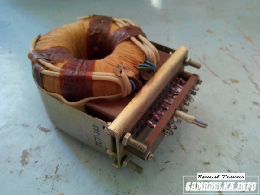
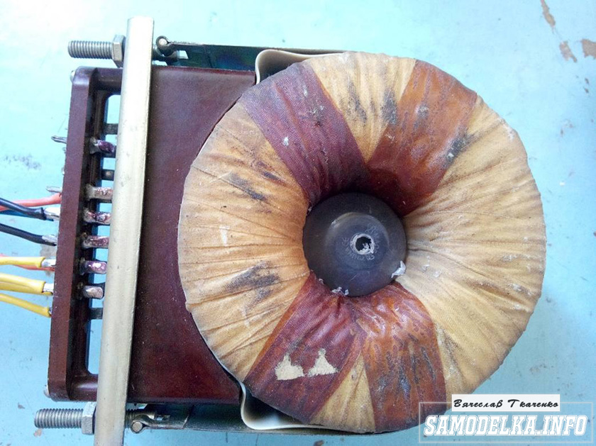
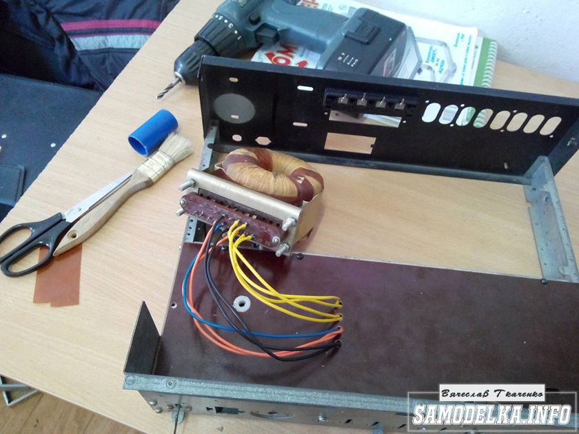
I'll start the assembly and at the same time describe it. The heart of the power supply (and of the entire amplifier, probably) will be the TST-143 toroidal transformer, which I once (4 years ago) tore out of some tube generator right as it was being taken to a landfill. Unfortunately, I didn’t manage to do anything else. It’s a pity for such a generator, but maybe it was still working or could have been repaired... Okay, I digress. Here he is my security officer.

Of course, I found a diagram for it on the Internet.

The rectifier will be on a diode bridge with a filter on the inductor for anode power. And 12 volts to power the backlight and anode voltage. This is the throttle I have.
Its inductance was 5 henry (according to the device), which is quite enough for good filtration. And the diode bridge was found like this.

Its name is BR1010. (10 amps 1000 volts). I'm starting to cut out the amplifier. I think it will be something like this.

I mark and cut holes in the PCB for the sockets for the light bulbs.
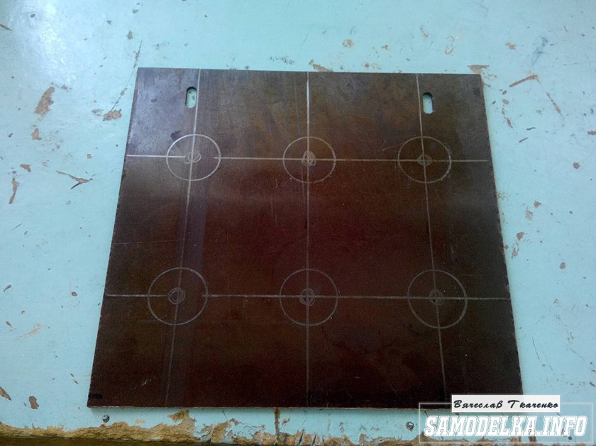


It turns out well :) I like everything so far.

This way and that way. drill and saw :)


Something began to emerge.

I found a fluoroplastic wire in old supplies and immediately all the alternatives and compromises regarding the wire for installation disappeared without a trace :) .
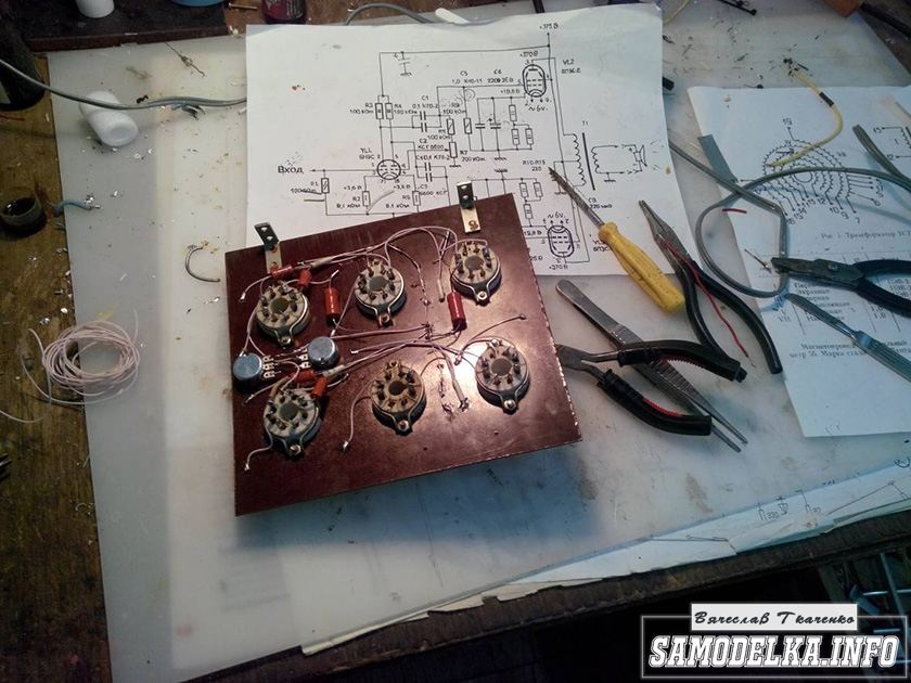

This is how the installation turned out. Everything seems to be “kosher”, the heat is intertwined, the ground is practically at one point. Should work.

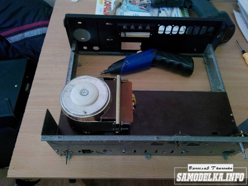
It's time to fence in food. After checking and testing all the output windings of the trans, I soldered all the necessary wires to it and began installing it according to the accepted plan.

As you know, in our life it’s not easy to go anywhere without improvised materials: this is how the Kinder Surprise container came in handy.
And the lid from Nescafe and old compact disk


I tore out the circuit boards of TVs and monitors. All containers are at least 400 volts (I know that I should have more, but I don’t want to buy them).

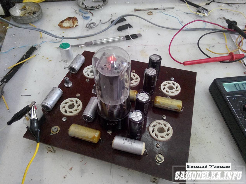
I bridge the bridge with containers (whatever were on hand, I’ll probably change them later)

It’s a bit much, but oh well, it will sag under load :)

I use the standard power switch from the amplifier (clear and soft).
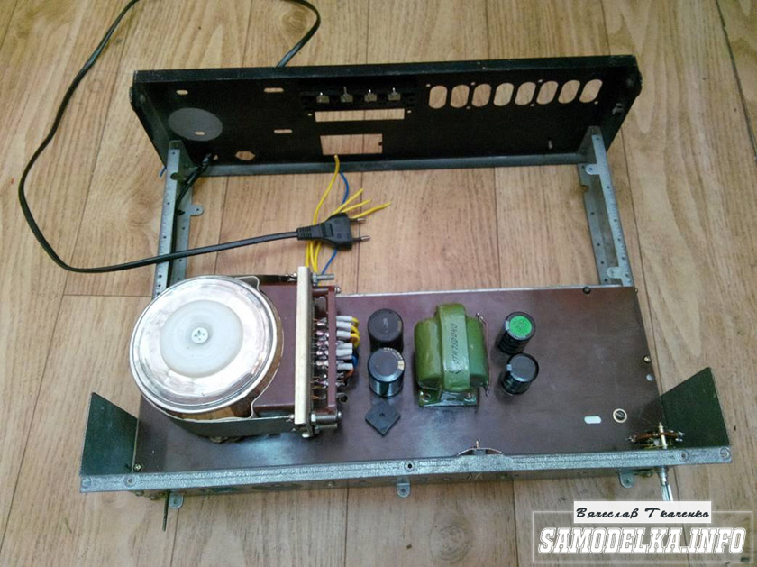
We're done with that. It turned out well :)
Backlight for tube amplifier housing.
To implement the backlight, an LED strip was purchased.

And installed in the housing as follows.

Now the glow of the amplifier will be visible during the daytime. To power the backlight, I will make a separate rectifier with a stabilizer on some KRKEN-like microcircuit (which I can find in the trash), from which I plan to power the anode voltage supply delay circuit.
Delay relay.
Having rummaged through the bins of my homeland, I found this completely untouched thing.
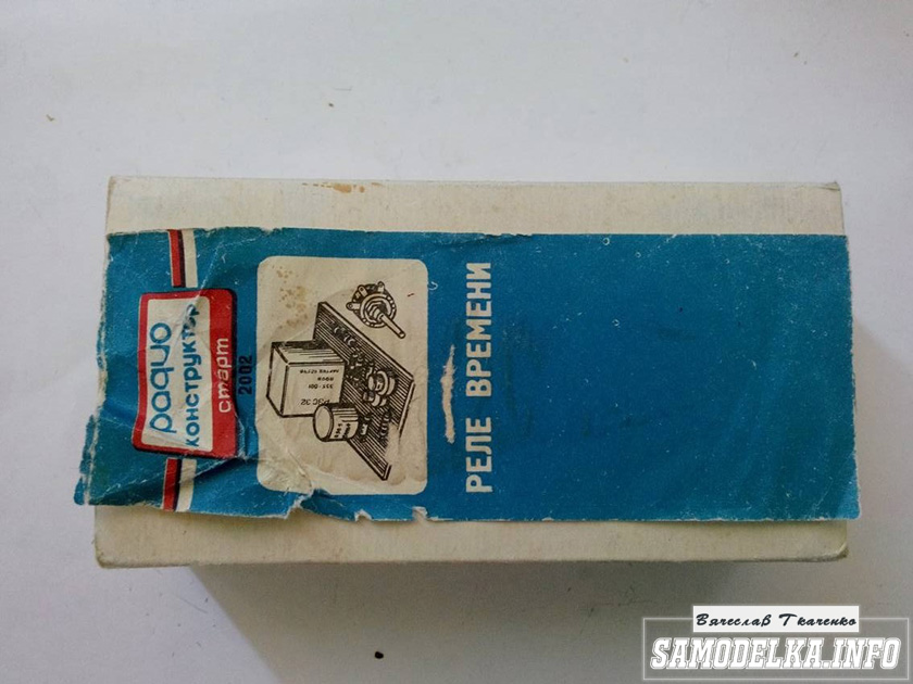
This is a radio time relay designer for a photo enlarger.
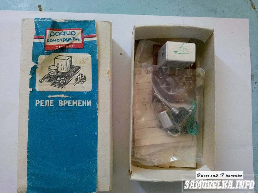

We collect, check, try on.

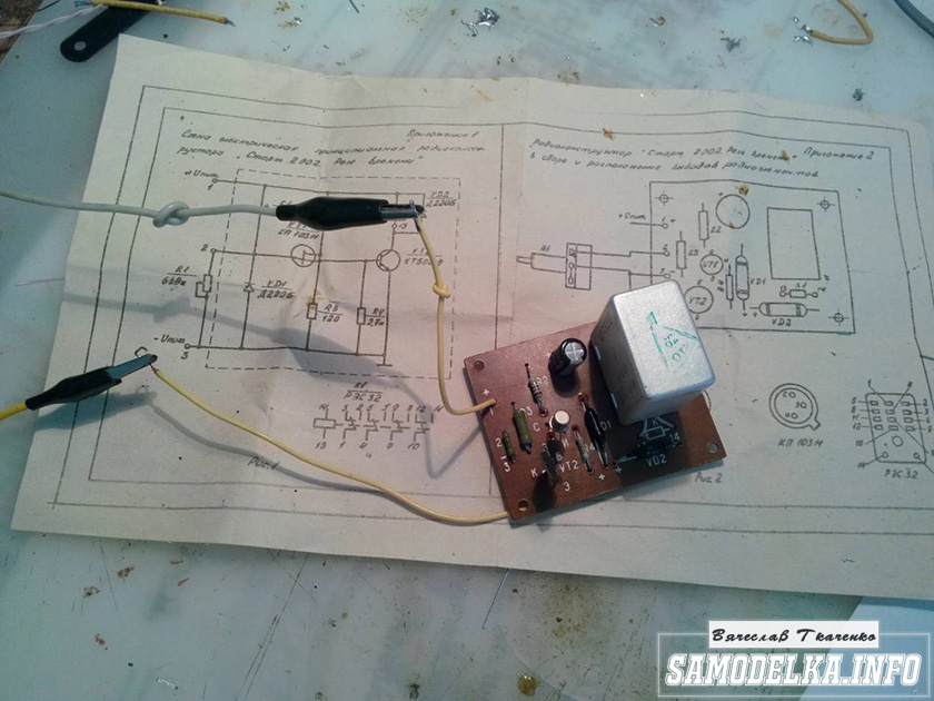
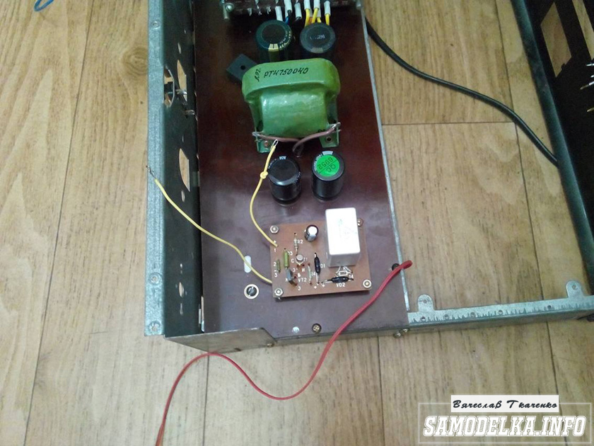
I set the response time to about 40 seconds, and replaced the variable resistor with a constant one. The matter is coming to an end. All that remains is to put everything together, install the face, indicators and regulators.
Regulators (input variables)
They say the sound quality can greatly depend on them. In short, I installed these
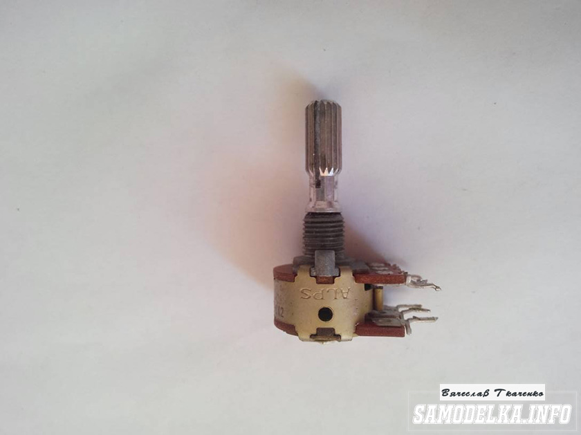
Dual 100 kOhm. Since I have two of them, I decided to parallel the pins, thereby obtaining 50 kOhm and increased resistance to wheezing :)
Indicators.
I used standard indicators, with standard backlighting

I mercilessly copied the connection diagram from the original board and used it as well.

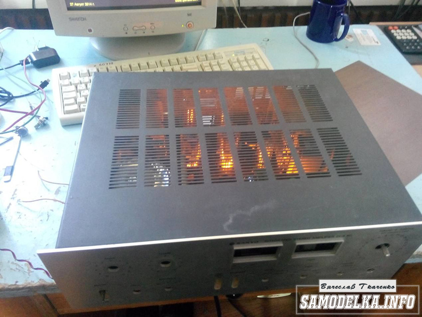
This is what I ended up with.


When checking the power, the amplifier demonstrated an output voltage of 10 volts of an undistorted sine wave with a frequency of 1000 Hz into a 4 ohm load (25 watts) equally across channels, which was pleasing :)
When listening, the sound was crystal clear without background and dust, as they say, but too monitory, or what? beautiful, but flat.
I naively believed that he would play without timbres, but...
Using a software equalizer, we managed to get a very beautiful sound that everyone liked. Thank you all very much!!!
It is based on the circuit design of the amplifier A. Manakov. I couldn't find 6e5p, so I decided to try 6p15p and 6p14p. It seemed to me that 6p14p sounds better, and it is also more accessible. The 6p45s lamp does not behave stable at a fixed bias (the current floats). With auto-bias, there is a high power dissipation on the cathode resistor. I chose a compromise option - semi-automatic offset. The 150 Ohm cathode resistor is shunted by a 2200 μF* 35 V capacitor. The grid is supplied with a negative bias from a separate low-power transformer (you can add an additional winding to the TS-180). I used a 12V transformer from a low-power power supply (50-200mA), connecting the secondary to a 6.3V filament winding. TS-180 was used as a power source.
The best option is to use two TS-180 (two monoblocks) or one TS-270.
As an output, you can use TS-180 without alteration (with the obligatory non-magnetic gap), but it is better to rewind, since without rewind there will be a decline in the tops and bottoms. The primary winding (750 turns on each coil, wire diameter 0.3-0.35 mm) is located between parts of the secondary (120+120 turns on each coil, diameter 0.6-0.7 mm). Two primary windings are connected in series, four secondary windings are connected in parallel (for a load of 8 ohms).
It’s better, of course, to buy a branded trans, but it costs a lot of money. You decide.
Many people believe that it is impossible to make a good trance out of TS-180 iron. Maybe this is not ideal, but for free...
Nevertheless, this is what happened - Fn-23Hz. Fv-26000Hz at a level of -1dB. Measured at a power of 4 watts. The power before the start of the sine wave limitation (or rather, rounding) is 8W. Maximum - 12W.
Amplifier circuit using 6p14p-6p45s tubes

Power supply diagram

I offer a well-developed UCH scheme on 6p45s, with a five-band tone block. The amplifier is made according to a classic single-ended circuit. The scheme of A. Manakov was taken as a basis. The diagram does not need a description of the operation.
During the assembly and setup process, some resistor values were changed. During the setup process, you will need to select R23, R34 so that the voltage at the 6p14p anodes is 190V. Then, by selecting R45, we set the anode voltage to 6N3P 90-110V.
You may have to select the resistance R22, R33, the voltage at pin 9 is set to 90V. The negative voltage on the 6p45s control grid can be from 45 to 70V, it all depends on the lamps used and the degree of wear. For me this value is 54V. This completes the setup.
Tone control circuit (equalizer)
I used a BA3822LS circuit as a tone block. This microcircuit has good parameters and is available for sale. Our price is 69 rubles. The advantages of such a circuit solution are the absence of a bunch of shielded wires and screens; in the absence of a signal, no background noise or hiss is observed.
It is advisable to connect the finished tone block to the ULF input through trimming resistors of 100 kohms, since the microcircuit has a sufficiently high gain level.

Initially, instead of a microcircuit, I used a similar circuit with two 6n3p lamps, but in the end I abandoned it due to the impossibility of getting rid of interference and background due to weak shielding of the lamps and the entire circuit due to insufficient space in the case.
I will note that the control unit on the lamps still sounds warmer, it seems to me. For those who are interested in this option, the diagram is also attached.

Design of the power supply and amplifier housing
Now about the power supply for a tube amplifier. We took a ready-made TS270 transformer, just wound a few turns on top of the existing windings. The throttles were taken ready-made from... I don’t remember what. Or from a b&w TV or receiver... it is advisable to organize the power supply for each channel separately to reduce interference and distortion between them. I used one rectifier for both channels.
There was no particular desire to wind another winding, just like the wires in particular. Paid more attention to capacitors instead. Nothing like this was noticed; I made do with one step-up winding. The output transformers are homemade, such as ts-20 ts-30, whoever has them, with a horseshoe-shaped core.


We wind it this way: the primary is 94 turns with 0.47 wire, then 900 turns of the primary with 0.18 wire should turn out like this: 94/900/94/900/94/. We connect the primary to the secondary in parallel; we do not place any paper gaskets between the halves of the iron. We apply supermoment (second glue), assemble and put a bandage on top of the iron if there is one, if not, then we clamp the iron until the glue dries completely.
The advantage of this solution is that it does not make noise during operation (provided the iron is good and the windings are tightly laid), the iron holds securely and, if necessary, can be easily disassembled - just hit it lightly with something heavy at the gluing site.
For the body I used 3mm aluminum sheets. The adjustment handles are decorative duralumin handles for furniture doors; the holes are drilled to the required diameter and put on via heat shrink directly onto the alternators.
The body is painted with auto enamel and half is covered with wood-like film. I made the power supply transformer remote in order to reduce its influence on the power supply. The trans was packaged in a case from an old power supply unit, connected to the amplifier with a 6-core cable through a connector on the case of the amplifier. The cable is assembled by hand. There is an inaccuracy in the diagram: R40 AND R29 ARE USUAL MLT-2. BUT R28 R39 must be five-watt!