PWM chip with digital control. PWM controller: circuit, principle of operation, control
Read also
For example);
Instructions for using PWM in Arduino
1 General information about pulse width modulation
Arduino digital pins can only output two values: logic 0 (LOW) and logic 1 (HIGH). That's why they are digital. But Arduino has “special” pins, which are designated PWM. They are sometimes indicated by a wavy line “~” or circled or otherwise distinguished from others. PWM stands for Pulse-width modulation or pulse width modulation, PWM.
A pulse-width modulated signal is a pulse signal of constant frequency, but variable duty cycle(the ratio of the pulse duration and its repetition period). Due to the fact that most physical processes in nature have inertia, sudden voltage drops from 1 to 0 will be smoothed out, taking on some average value. By setting the duty cycle, you can change the average voltage at the PWM output.
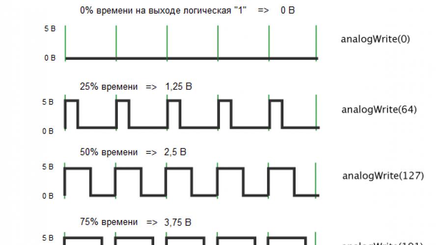
If the duty cycle is 100%, then the digital output of the Arduino will always have a logical voltage of “1” or 5 volts. If you set the duty cycle to 50%, then half the time the output will be logical "1" and half the time - logical "0", and the average voltage will be 2.5 volts. And so on.

In the program, the duty cycle is specified not as a percentage, but as a number from 0 to 255. For example, the command analogWrite(10, 64) will tell the microcontroller to send a signal with a duty cycle of 25% to digital PWM output No. 10.
Arduino pins with pulse width modulation function operate at a frequency of about 500 Hz. This means that the pulse repetition period is about 2 milliseconds, which is measured by the green vertical strokes in the figure.
It turns out that we can simulate an analog signal on a digital output! Interesting, isn't it?!How can we use PWM? Lots of applications! For example, control the brightness of an LED, motor rotation speed, transistor current, sound from a piezo emitter, etc...
2 Diagram for demonstration Pulse Width Modulation in Arduino
Let's look at the most basic example - controlling the brightness of an LED using PWM. Let's put together a classic scheme.

3 Sketch example with PWM
Let's open the "Fade" sketch from the examples: File Samples 01.Basics Fade.

Let's change it a little and load it into the Arduino memory.
Int ledPin = 3; // declare a pin that controls the LED int brightness = 0; // variable for setting brightness int fadeAmount = 5; // brightness change step void setup() ( pinMode(ledPin, OUTPUT); } void loop() ( analogWrite(ledPin, brightness); // set the brightness on the ledPin pin brightness += fadeAmount; // change the brightness value /* when reaching the limits 0 or 255, change the direction of the brightness change */ if (brightness == 0 || brightness == 255) ( fadeAmount = -fadeAmount; // change the sign of the step ) delay(30); // delay for greater visibility of the effect }
4 LED brightness control using PWM and Arduino
Turn on the power. The LED gradually increases brightness and then smoothly decreases. We simulated an analog signal at the digital output using pulse width modulation.

Watch the attached video, which clearly shows the change in the brightness of the LED; on the connected oscilloscope you can see how the signal from the Arduino changes.
Let's look at what PWM or PWM is. And also, what is the difference between PWM and WIDTH. The pulse width modulation algorithm is used to smoothly change the power to the load coming from the power source. For example, to regulate the speed of rotation of the motor shaft; smoothness of changes in the brightness of lighting or backlight. A separate wide area of application of PWM are switching power supplies and autonomous inverters.
To power a load, it is often necessary to change the voltage supplied from the power source. In principle, two methods of voltage regulation can be distinguished: linear and pulsed.

An example of the linear method would be. In this case, a significant part of the power is lost through the resistor. The greater the difference in voltage between the power source and the consumer, the greater the loss of power, which simply “burns” on the resistor, turning into heat. Therefore, it is rational to use the linear control method only when there is a small difference between the input and output voltages. Otherwise, the efficiency of the power supply as a whole will be very low.

In modern converter technology, pulsed power control at the load is predominantly used. One of the ways to implement pulse regulation is pulse width modulation PWM . In English literature PWM – pulse-width modulation .

Pulse control principle
The main elements of any type of switching power regulator are semiconductor switches - transistors or thyristors. In its simplest form, the circuit of a switching power supply is as follows. Constant voltage source Uip key K connected to the load N. Key TO switches at a certain frequency and remains in the on state for a certain duration of time. In order to simplify the diagram, I do not depict other required elements on it. In this context, we are only interested in the operation of the key TO.

To understand the PWM principle, we will use the following graph. Let us divide the time axis into equal intervals, called period T. Now, for example, we will close the key for half the period K. When the key is closed, to the load N voltage is supplied from the power source Uip. The second part of the half-cycle of the key is in the closed state. And the consumer will be left without power.

The time during which the key is closed is called pulse time t . And the duration of the open key is called pause time tп . If you measure the voltage across the load, it will be equal to half Uip.
The average voltage across the load can be expressed by the following relationship:
Uav.n = Uip ti/T.
Pulse time ratio t and to the period T called duty cycle D . And the reciprocal of it is called duty cycle :
S = 1/D = T/ti.
In practice, it is more convenient to use the fill factor, which is often expressed as a percentage. When the transistor is fully open throughout the entire time, the duty cycle D is equal to one or 100%.
If D = 50%, then this means that half the time during the period the transistor is in the open state, and half in the closed state. In this case, the signal shape is called a square wave.
Therefore, by changing the coefficient D from 0 to unity or to 100%, you can change the value of Uav.n from 0 to Uip:
Uav.n = Uip∙D.
And accordingly regulate the amount of power supplied:
Pav.n = Pip∙D.
In Western literature, there is practically no distinction between the concepts of pulse-width regulation of WID and pulse-width modulation of PWM. However, we still have a difference between them.
Nowadays, many microcircuits, especially those used in DC-DC converters, implement the WID principle. But at the same time they are called PWM controllers. Therefore, now there is practically no difference in name between these two methods.
 In any case, to form a certain pulse duration supplied to the base of the transistor and opening the latter, reference and setting voltage sources, as well as a comparator, are used.
Let's consider a simplified circuit in which the battery GB supplies the consumer Rн in a pulsed manner through the transistor VT. I’ll say right away that in this circuit I specifically did not use such elements necessary for the operation of the circuit: a capacitor, an inductor and a diode. This is done to simplify the understanding of the operation of the PWM, and not the entire converter.
To put it simply, a comparator has three terminals: two inputs and one output. The comparator works as follows. If the voltage value at the “+” input pin (non-inverting input) is higher than at the “-” input (inverting input), then the output of the comparator will be a high level signal. Otherwise - low level.
In our case, it is the high level signal that opens the transistor VT. Let's consider how the required pulse time duration ti is formed. To do this, we will use the following graph.

With WID, a sawtooth signal of a given frequency is supplied to one input of the comparator. It is also called the support. The second input is supplied with a reference voltage, which is compared with the reference voltage. As a result of the comparison, a pulse of the appropriate duration is formed at the output of the comparator.
If there is a reference signal at the non-inverting input of the comparator, then there will be a pause first, and then a pulse. If a master signal is applied to the non-inverting input, there will first be a pulse, then a pause.
![]()
Thus, by changing the value of the specified signal, you can change the duty cycle, and, accordingly, the average voltage across the load.
They strive to make the frequency of the reference signal maximum in order to reduce the parameters of the chokes and capacitors (not shown in the diagram). The latter leads to a reduction in the weight and dimensions of the switching power supply.
PWM – pulse width modulation
PWM is predominantly used to generate a sinusoidal signal. PWM is often used to control the operation of an inverter converter. The inverter is designed to convert DC energy into AC energy.
Let's consider the simplest scheme.
![]()
At one point in time, a pair of transistors VT1 and VT3 opens. A path is created for the flow of current from the battery GB through the active-inductive load RнLн. At the next moment, VT1 and VT3 are locked, and diagonally opposite transistors VT2 and VT4 are open. Now current flows from the battery through RnLn in the opposite direction. Thus, the current across the load changes its direction and is therefore variable. As you can see, the load current is not sinusoidal. Therefore, PWM is used to obtain a sinusoidal current waveform.
![]()
There are several types of PWM: unipolar, bipolar, one-way, two-way. Here we will not dwell on each specific type, but will consider the general approach.
A sinusoid is used as a modulating signal, and a triangular signal is used as a reference signal. As a result of comparing these signals, the durations of pulses and pauses are formed (lower graph), which control the operation of transistors VT1...VT4.
Please note that the amplitude of the voltage across the load is always equal to the amplitude of the power supply. The pulse repetition period also remains unchanged. Only the width of the opening pulse changes. Therefore, when a load is connected, the current flowing through it will have a sinusoidal shape (shown by the dotted line in the lower graph).
So, the main difference between WIDTH and PWM is that with pulse-width control, the pulse and pause times remain constant. And with pulse-width modulation, the durations of pulses and pauses change, which makes it possible to realize an output signal of a given shape.

LEDs are used in almost all technology around us. True, sometimes it becomes necessary to adjust their brightness (for example, in flashlights or monitors). The easiest way out in this situation seems to be to change the amount of current passed through the LED. But that's not true. The LED is a fairly sensitive component. Constantly changing the amount of current can significantly shorten its life, or even break it. It is also necessary to take into account that you cannot use a limiting resistor, since excess energy will accumulate in it. This is unacceptable when using batteries. Another problem with this approach is that the color of the light will change.
There are two options:
- PWM regulation
- Analog
These methods control the current flowing through the LED, but there are certain differences between them.
Analog control changes the level of current that passes through the LEDs. And PWM regulates the frequency of current supply.
PWM regulation
A way out of this situation may be to use pulse width modulation (PWM). With this system, the LEDs receive the required current, and the brightness is adjusted using high-frequency power supply. That is, the frequency of the feeding period changes the brightness of the LEDs.
The undoubted advantage of the PWM system is maintaining the productivity of the LED. The efficiency will be about 90%.
Types of PWM regulation
- Two-wire. Often used in car lighting systems. The converter's power supply must have a circuit that generates a PWM signal at the DC output.
- Shunt device. To make the on/off period of the converter use a shunt component that provides a path for the output current other than the LED.
Pulse parameters for PWM
The pulse repetition rate does not change, so there are no requirements for it in determining the brightness of the light. In this case, only the width, or time, of the positive pulse changes.

Pulse frequency
Even taking into account the fact that there are no special complaints about the frequency, there are limit values. They are determined by the sensitivity of the human eye to flickering. For example, in a movie, frames must flash at 24 frames per second for our eyes to perceive it as one moving image.
In order for flickering light to be perceived as uniform light, the frequency must be at least 200 Hz. There are no restrictions on the upper indicators, but there is no way lower.
How does a PWM regulator work?
A transistor key stage is used to directly control the LEDs. Typically, they use transistors that can accumulate large amounts of power.
This is necessary when using LED strips or high-power LEDs.
For small quantities or low power, the use of bipolar transistors is sufficient. You can also connect LEDs directly to microcircuits.
PWM generators
In a PWM system, a microcontroller or a circuit consisting of low-integration circuits can be used as a master oscillator.
It is also possible to create a regulator from microcircuits that are designed for switching power supplies, or K561 logic chips, or NE565 integrated timer.
Craftsmen even use an operational amplifier for these purposes. To do this, a generator is assembled on it, which can be adjusted.
One of the most used circuits is based on the 555 timer. It is essentially a regular square wave generator. The frequency is regulated by capacitor C1. at the output the capacitor must have a high voltage (this is the same with the connection to the positive power supply). And it charges when there is a low voltage at the output. This moment gives rise to pulses of different widths.
Another popular circuit is PWM based on the UC3843 chip. in this case, the switching circuit has been changed towards simplification. In order to control the pulse width, a control voltage of positive polarity is used. In this case, the output produces the desired PWM pulse signal.
The regulating voltage acts on the output as follows: as it decreases, the width increases.

Why PWM?
- The main advantage of this system is its ease. The usage patterns are very simple and easy to implement.
- The PWM control system provides a very wide range of brightness adjustment. If we talk about monitors, it is possible to use CCFL backlight, but in this case the brightness can only be reduced by half, since CCFL backlight is very demanding on the amount of current and voltage.
- Using PWM, you can keep the current at a constant level, which means the LEDs will not be damaged and the color temperature will not change.
Disadvantages of using PWM
- Over time, image flicker can be quite noticeable, especially at low brightness or eye movement.
- If there is constant bright light (such as sunlight), the image may become blurry.
8. Pulse width modulation in converters
8.1. General information
The principles of pulse control and modulation are discussed in Chapter. 4 using the example of a simple DC regulator circuit. At the same time, definitions are given of the main types of pulse modulation used in the theory of linear pulse systems, which correspond to the practice of controlling pulsed DC converters.
However, pulse-width modulation of voltages or currents in AC converters has a slightly different definition in power electronics, taking into account the features of PWM when solving problems of converting electricity using alternating current. As defined in IEC 551-16-30, pulse width modulation is a pulse control in which the width or frequency of the pulses, or both, are modulated within a period of the fundamental frequency to produce a specific output voltage waveform. In most cases, PWM is carried out in order to ensure the sinusoidality of the voltage or current, i.e., reducing the level of higher harmonics relative to the main (first) harmonic, and is called sinusoidal. There are the following main methods for ensuring sinusoidality: analog PWM and its modifications; selective (selective) suppression of higher harmonics; hysteresis or delta modulation;
space vector modulation.
The classic version of organizing an analog sinusoidal PWM is to change the width of the pulses that form the output voltage (current) by comparing a voltage signal of a given shape, called a reference or reference, with a triangular voltage signal having a higher frequency and called a carrier signal. The reference signal is modulating and determines the required shape of the output voltage (current). There are many modifications of this method in which the modulating signals are represented by special functions other than a sine wave. The lecture notes will discuss several basic circuits explaining these PWM methods.
The method of selective suppression of higher harmonics is currently successfully implemented using software-based microprocessor controllers. Hysteresis modulation is based on the principles of relay “tracking” of a reference signal, for example, a sinusoidal waveform. In its simplest technical design, this method combines the principles of PWM and PFM (pulse frequency modulation). However, through special circuit measures it is possible to stabilize the modulation frequency or limit the range of its change.
The space vector modulation method is based on converting a three-phase voltage system into a two-phase one and obtaining a generalized space vector. The magnitude of this vector is calculated at moments determined by the fundamental and modulating frequencies. It is considered very promising for controlling three-phase inverters, in particular, when used in electric drives. At the same time, it is in many ways similar to traditional sinusoidal PWM.
Control systems based on PWM allow not only to provide a sinusoidal shape of the average values of the fundamental harmonic of voltage or current, but also to control the values of its amplitude, frequency and phase. Since in these cases the converter uses fully controlled switches, it becomes possible to implement the operation of AC (DC) converters together with the AC network in all four quadrants in both rectifying and inverting modes with any given value of the fundamental harmonic power factor cosφ in range from -1 to 1. Moreover, with increasing carrier frequency, the possibilities of reproducing current and voltage of a given shape at the output of inverters expand. This allows you to create active filters to suppress higher harmonics.
We will consider the main definitions used in the further presentation using the example of the application of the first method in a single-phase half-bridge circuit of a voltage inverter (Fig. 8.1, A). In this conditional diagram the keys S1 And S2 are represented by fully controlled switching elements, supplemented by diodes connected in series and parallel to them. Series diodes reflect the unidirectional conductivity of switches (for example, transistors or thyristors), and parallel diodes provide conduction of reverse currents with an active-inductive load.
Diagrams of reference, modulating u M(θ) and carrier u H (θ) signals are shown in Fig. 8.1, b. Formation of key control pulses S 1 and S 2 is carried out according to the following principle. At u M (θ) > u H(θ) key S 1 is on, a S 2 switched off. At u M(θ)< u H (θ) key states are reversed: S 2 - on, a S 1 - off. Thus, a voltage is generated at the inverter output in the form of two polar pulses. In real circuits to eliminate simultaneous conduction of switches S 1 and S 2, a certain delay should be provided between the moments of generating signals to turn on these keys. Obviously, the pulse width depends on the ratio of the signal amplitudes u M(θ) and u H(θ). The parameter characterizing this relationship is called the amplitude modulation index and is determined by formula (8.1):
, (8.1.)
Where U M m and U H m - maximum values of the modulating signal u M(θ) and carrier signal u H(θ) respectively.


Rice. 8.1. Single phase semi bridge voltage inverter: A- scheme; b– voltage diagrams for pulse modulation
Carrier frequency u H(θ) is equal to the switching frequency f H keys S 1 and S 2 and usually significantly exceeds the frequency of the modulating signal f M. Frequency ratio f H and f M is an important indicator of the efficiency of the modulation process and is called the frequency modulation index, which is determined by formula (8.2):
At small values M f signals u M(θ) and u H(θ) must be synchronized to avoid unwanted subharmonics. B as maximum value My, which determines the need for synchronization, is set M f = 21. Obviously, with synchronized signals the coefficient M f is a constant value.
From the diagram in Fig. 8.1 it can be seen that the amplitude of the first harmonic of the output voltage U am 1 can be presented, taking into account (8.1), in the following form (8.3):
![]() (8.3)
(8.3)
According to (8.3) at M a = 1 amplitude of the first harmonic of the output voltage is equal to the height of the half-wave rectangle U d/2. The characteristic dependence of the relative value of the first harmonic of the output voltage on the value of M a is shown in Fig. 8.2, from which it is clear that the change M a from 0 to 1 linearly and depends on the amplitude U am 1. Limit value M a is determined by the principle of the type of modulation under consideration, according to which the maximum value U am 1 is limited by the height of the half-wave of a rectangular shape, equal to U d/2. With a further increase in the coefficient M a modulation leads to a nonlinear increase in amplitude U am 1 to the maximum value determined by the formation of a rectangular voltage at the output of the inverter, which subsequently remains unchanged.
Expanding the rectangular function into a Fourier series gives the maximum value (8.4):
![]() (8.4)
(8.4)
This value is limited by the index value M a, varying in the range from 0 to approximately 3. Obviously, the function in the interval a-b values from 1 to 3.2 is nonlinear (Fig. 8.2). The operating mode in this section is called over modulation.
Meaning M f determined by the choice of carrier signal frequency u H (θ) and significantly affects the technical characteristics of the converter. As the frequency increases, switching losses in the power switches of the converters increase, but at the same time the spectral composition of the output voltage improves and the solution to the problem of filtering higher harmonics caused by the modulation process is simplified. An important factor in choosing a value f H in many cases is the need to ensure its value in the audio frequency range of more than 20 kHz. When choosing f H you should also take into account the level of operating voltages of the converter, its power and other parameters.

Rice. 8.2. Dependence of the relative value of the amplitude of the fundamental harmonic of the output voltage on the amplitude modulation index for a single-phase half-bridge circuit
The general trend here is an increase in the values of M f low power and low voltage converters and vice versa. So the choice M f is a multicriteria optimization problem.
Pulse modulation with stochastic process. The use of PWM in converters is associated with the appearance of higher harmonics in modulated voltages and currents. Moreover, in the spectral composition of these parameters, the most significant harmonics occur at frequencies that are multiples of the frequency modulation index M f and harmonics with decreasing amplitudes grouped around them at side frequencies. Higher harmonics can cause the following main problems:
occurrence of acoustic noise;
deterioration of electromagnetic compatibility (EMC) with other electrical devices or systems.
The main sources of acoustic noise are electromagnetic components (chokes and transformers), which are exposed to current and voltage containing higher harmonics with frequencies in the audio range. It should be noted that noise can occur at certain frequencies where higher harmonics are greatest. Noise-causing factors, such as magnetostriction, make EMC problems more difficult to resolve. EMC problems can occur over a wide frequency range, depending on the EMI sensitivity of electrical devices. Traditionally, design and technology solutions have been used to reduce noise levels, and passive filters have been used to ensure EMC.
As a promising direction for solving these problems, methods associated with changing the nature of the spectral composition of modulated voltages and currents are considered. The essence of these methods is to level the frequency spectrum and reduce the amplitude of pronounced harmonics due to their stochastic distribution over a wide frequency range. This technique is sometimes called “smearing” the frequency spectrum. The concentration of interference energy decreases at frequencies where harmonics can have maximum values. The implementation of these methods is not associated with any impact on the components of the power part of the converters and in most cases is limited by software with minor changes to the control system.
Let us briefly consider the principles of implementation of these methods. PWM is based on changing the duty cycle γ= t And / T n, Where t and - pulse duration; T n- the period of its formation. Usually these quantities, as well as the position of the pulse on the period interval T n are constant in steady state conditions. PWM results are defined as integral average values. In this case, the deterministic values of t and and, including the pulse position, determine the unfavorable spectral composition of the modulated parameters. If these quantities are given a random character while maintaining a given value of γ, then the processes become stochastic and the spectral composition of the modulated parameters changes. For example, such a random character can be given to the position of the impulse t and on the interval of period T n or provide a stochastic change in the latter. For this purpose, a random number generator can be used, influencing the modulation frequency master generator f n =1/T n. In a similar way, you can change the position of the pulse over the interval T n with mathematical expectation equal to zero. The averaged integral value γ must remain at the level specified by the control system, as a result of which the spectral composition of higher harmonics in modulated voltages and currents will be equalized.
Questions for self-control
1. List the main PWM methods for ensuring a sinusoidal current or voltage.
2. What is the difference between unipolar voltage modulation and bipolar one?
3. List the main parameters of PWM.
4. For what purpose is PWM with stochastic processes used?
Misunderstanding of the operation of PWM or PWM (Pulse-width modulation) often leads not only to their incorrect use, but even to errors in the design of devices that use PWM for control. Here, limiting ourselves to a specific application, I will try to tell you what PWM is, why it is required and how it works.
First, what is PWM.
When is PWM needed?
The main reason for using PWM is the need to provide low DC voltage to power electronics devices while maintaining high efficiency, especially in controlled electric drives.
In internal networks of equipment, DC voltage of a limited set of voltages is used to power devices, which often need to be changed to suit the requirements of a particular device, stabilize or regulate it.
These can be DC electric drives, chips, radio equipment components.
Adjustment can be carried out using voltage damping devices: resistors, transistors (if adjustment is required). The main disadvantage of this solution is power loss and increased heat generation on control devices.
Since it is known that the released power is equal to:
P = I x U or P = I 2 x R W.
then the greater the current I in the circuit and the voltage drop U, the greater the power loss. Here R is the resistance value of the control element.
This applies to quenching resistors and semiconductor devices too.
But it is well known that semiconductor devices work very well (with low losses and heat generation) as switches when they have only two open/closed states.
This mode allows you to reduce losses on the switching semiconductor device to the level:
P max = I x U us
U us for modern semiconductor switches approaches 0.3v and with a current consumption of 10 A, power losses will approach 3 W.
|
This is in switch mode, and when working in PWM devices it is even less. PWM uses semiconductor devices in switching mode as key elements, that is, the transistor is either open (turned off) or closed (in a state of saturation) all the time. In the first case The transistor has almost infinite resistance, so the current in the circuit is very small, and although all the supply voltage drops across the transistor, the power released by the transistor is practically zero. In the second case The resistance of the transistor is extremely low, and, therefore, the voltage drop across it is close to zero - the power released is also small. In transition states |
(transition of a switch from a conducting state to a non-conducting state and back) the power released in the switch is significant, but since the duration of the transition states is extremely short in relation to the modulation period, the average power of switching losses turns out to be insignificant.
The use of PWM made it possible to realize the advantages of the key mode in circuits that reduce and regulate DC voltage.
I repeat, pulse-width modulation is the control of the average voltage value on the integrating load by changing the duty cycle of the pulses using a control key.
The operation of PWM on an integrating load is shown in Fig. 1.
Picture 1
The main condition for such use of PWM is the presence of an integrating load.
Because the amplitude value of the voltage is equal to E.
These can be integrating RC, LC, RLC or RL circuits and mechanical integrators (for example an electric motor).
When PWM operates on an integrating load, the voltage - the equivalent DC voltage changes depending on the duty cycle (Q) of the pulses.< 1
Q = t and /T
here: Q - duty cycle, t and - pulse duration, T - pulse repetition period.
Taking into account the duty cycle, the equivalent DC voltage will be equal to:
here: E eq - equivalent direct voltage (Volts), Q - duty cycle, E - voltage of the source from which the PWM converter is powered (Volts).
In reality, a voltage equal to E is applied to the PWM load terminals, and the work done by the electric current (or the number of revolutions of the electric motor) is determined precisely by E eq. When restoring on the integrating capacitor we obtain exactly the voltage E equivalent.
The power allocated to the control switch controlled by PWM is equal to:
P max = Q x I x U us
Load connection diagram to PWM.
PWM does not require any circuit solutions different from the DC motor switching circuit (a special case of load). The electric motor is simply connected to a power source operating in PWM mode. Unless, in certain situations, it is necessary to introduce additional filtering of noise arising on the fronts of pulses. This filter in Fig. 2 in the form of capacitors and a damping diode.

Figure 2
In Fig. 2 shows such a connection.
We see that the switch (field-effect transistor) can simply be replaced with a variable resistor.
PWM circuit
In the article "Adapter for 3 pin to 4 pin fan" http://de1fer.ru/?p=45#more-45 the blog owner provides a diagram of a fan with P WM.

Figure 3
here: GND - ground (common), Control - contact P WM control, +12 - supply voltage, Sense - speed sensor output.
In this circuit, control is possible rather with direct current +I control than with a PWM signal.
To control a pulse (PWM) signal, the circuit shown in Fig. is required. 4. And judging by the parameters of the “PWM” transistor, it was chosen specifically for direct current control. At least it will work normally in this mode with a fan up to 1.6 W.

Figure 4
But in pulse mode without capacitor C, the BC879 transistor will heat up a little less than at direct current and the electric motor can stop at short current pulse durations (low speeds) due to its integration at the input capacitance C input of the transistor.
Main parameters of silicon bipolar high-frequency npn transistor BC879 from SIEMENS
| PC max | Ucb max | Uce max | Web max | Icmax | Tj max, °C | Ft max |
| 800mW | 100V | 80V | 5V | 1A | 150°C | 200MHz |
If necessary, disable PWM (PWM) control in the circuit shown in Fig. 3 you just need to connect the Control pin to the +12v wire.
There is another version of the fan circuit with P WM on the Radeon.ru forum

Figure 5
Significant differences from Fig. 3 no, only a MOS field-effect transistor with a built-in or induced p-type channel is used as a PWM-controlled switch.
This circuit can also be controlled by both P WM and constant voltage (but it’s not worth the risk - you need to know the parameters of the transistor).
This circuit is fully operational and does not have the disadvantages of the circuit shown in Fig. 3.
To turn it off (depending on the type of transistor), just connect the Control pin to the + or - wire.
Attention DIYers!
If you are not satisfied with the PWM control algorithm built into the motherboard (system) board.
And you have a reobas (fan control controller) that suits you, then use a fan with a 3-pin connector.
If a fan with PWM is dear to you or does not have a replacement, then you need to disable PWM using the method described above, replacing the 4-pin connector with a 3-pin one and connecting it to the rheobass.
But remember, using a PWM fan in any abnormal mode will not allow you to achieve its maximum performance.
The use of DC current control simultaneously with PWM is not recommended due to a reduction in the fan supply voltage by 10-20%, which will not allow such a fan to reach full performance.
Use simultaneously with PWM - PWM along the power supply circuit can lead to periodic instability of the fan operation (sliding beats may occur between the frequencies of PWM - PWM along the power supply circuit of systems) and create ambiguity for systems equipped with a speed stabilization system. In addition, as in the previous case, the resulting voltage on the fan will decrease by 10-15%, which will not allow such a fan to reach full performance.
Conclusion
So stop at one thing. Either use a PWM fan, or use external fan control via the power supply circuit on a fan with a 3-pin connector.
The use of PWM or, as we used to say, PWM increases the efficiency of voltage-reducing DC devices, which reduces the overall heat generation of electronic devices with PWM.
PWM allows you to create compact high-power DC controlled electric drive systems.
In modern DC voltage control devices and step-down voltage stabilizers, adjustments are usually made using PWM. For this purpose, controllers are produced that require a minimum of attachments.
prepared by A. Sorokin,